EP0497116A2 - Récepteur de radiodiffusion avec RDS - Google Patents
Récepteur de radiodiffusion avec RDS Download PDFInfo
- Publication number
- EP0497116A2 EP0497116A2 EP92100371A EP92100371A EP0497116A2 EP 0497116 A2 EP0497116 A2 EP 0497116A2 EP 92100371 A EP92100371 A EP 92100371A EP 92100371 A EP92100371 A EP 92100371A EP 0497116 A2 EP0497116 A2 EP 0497116A2
- Authority
- EP
- European Patent Office
- Prior art keywords
- frequency
- identification code
- program identification
- data
- radio receiver
- Prior art date
- Legal status (The legal status is an assumption and is not a legal conclusion. Google has not performed a legal analysis and makes no representation as to the accuracy of the status listed.)
- Granted
Links
Images



Classifications
-
- H—ELECTRICITY
- H04—ELECTRIC COMMUNICATION TECHNIQUE
- H04H—BROADCAST COMMUNICATION
- H04H20/00—Arrangements for broadcast or for distribution combined with broadcast
- H04H20/20—Arrangements for broadcast or distribution of identical information via plural systems
- H04H20/22—Arrangements for broadcast of identical information via plural broadcast systems
-
- H—ELECTRICITY
- H04—ELECTRIC COMMUNICATION TECHNIQUE
- H04H—BROADCAST COMMUNICATION
- H04H20/00—Arrangements for broadcast or for distribution combined with broadcast
- H04H20/28—Arrangements for simultaneous broadcast of plural pieces of information
- H04H20/33—Arrangements for simultaneous broadcast of plural pieces of information by plural channels
- H04H20/34—Arrangements for simultaneous broadcast of plural pieces of information by plural channels using an out-of-band subcarrier signal
-
- H—ELECTRICITY
- H04—ELECTRIC COMMUNICATION TECHNIQUE
- H04H—BROADCAST COMMUNICATION
- H04H2201/00—Aspects of broadcast communication
- H04H2201/10—Aspects of broadcast communication characterised by the type of broadcast system
- H04H2201/13—Aspects of broadcast communication characterised by the type of broadcast system radio data system/radio broadcast data system [RDS/RBDS]
-
- H—ELECTRICITY
- H04—ELECTRIC COMMUNICATION TECHNIQUE
- H04H—BROADCAST COMMUNICATION
- H04H60/00—Arrangements for broadcast applications with a direct linking to broadcast information or broadcast space-time; Broadcast-related systems
- H04H60/35—Arrangements for identifying or recognising characteristics with a direct linkage to broadcast information or to broadcast space-time, e.g. for identifying broadcast stations or for identifying users
- H04H60/37—Arrangements for identifying or recognising characteristics with a direct linkage to broadcast information or to broadcast space-time, e.g. for identifying broadcast stations or for identifying users for identifying segments of broadcast information, e.g. scenes or extracting programme ID
Definitions
- the invention relates to a radio receiver with a device for decoding radio data signals according to the preamble of the main claim.
- RDS receiver In known radio receivers with a device for decoding radio data signals - hereinafter referred to as RDS receiver - in particular car radios, it is checked from time to time whether program identification codes - hereinafter referred to as PI codes - are tested by a test person received alternative frequency correspond to that of the respectively received frequency. This allows you to automatically switch to alternative frequencies while maintaining the program received. In the known RDS receivers, this test takes a time of 150 ms to 300 ms, which leads to annoying cracking noises, because as long as no audio signal from the received frequency is available.
- the object of the present invention is to enable an RDS receiver to test alternative frequencies for the presence of a program identification code in such a way that the reception of the station currently set is not impaired.
- the radio receiver according to the invention with the characterizing features of the main claim has the advantage that, despite a small outlay for only one receiving part and the good utilization of the antenna signal, it is possible to test the program identification code at alternative frequencies without the disturbances described above.
- the interruptions in reception required for testing in the radio receiver according to the invention last about 20 ms to 30 ms and are not perceived as disturbing.
- the total time of all interruptions required for testing in the radio receiver according to the invention can be greater than the interruption in the known radio receiver, but the short interruptions are distributed over the total time in such a way that they do not have a disturbing effect.
- a further development of the invention consists in that data samples, which contain an RDS data bit sequence, are taken from different groups at matching times within the groups of the radio data signal. This takes advantage of the fact that the program identification code is present in each group of the radio data signal. If the data samples taken according to this development are different, then they are either not parts of the program identification code or there is a transmission error in at least one of the data samples. Another time-consuming check can thus be avoided.
- all the bits belonging to the RDS signal can also be received and written into a microcomputer by a corresponding staggering of the time switches.
- the complete code including the check bits is then available for the evaluation.
- many data samples are required. In the further development specified below, however, it turns out, after possibly very few data samples, that the program identification code sought is not transmitted with the alternative frequency.
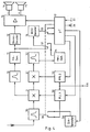
- the signal received by the antenna 1 is first fed to a selective pre-stage 2 and passes increasingly to the mixing stage 3.
- the tuning is carried out with the aid of a frequency-phase control loop (PLL), which consists of a controllable oscillator 4, a programmable frequency divider 5, a frequency-phase comparator 6 and a low-pass filter 7.
- the frequency-phase comparator 6 is supplied with a quartz-stable reference frequency at 8.
- the structure and the effect of a frequency-phase control loop are known per se and therefore need not be explained in more detail in connection with the present invention.
- the frequency of the controllable oscillator 4 can be predetermined via a control input 9 of the programmable frequency divider 5.
- the selective pre-stage 2 is tuned with the control voltage supplied to the controllable oscillator 4.
- the output signal of the mixer stage is passed via an IF amplifier 10 to the FM demodulator 11, at the output of which a multiplex signal (MPX) is available which, in addition to the audio information, contains the radio data signal.
- MPX multiplex signal
- the two audio signals L and R are generated in a stereo decoder 12 and are supplied to the loudspeakers 14, 15 via the NF stereo amplifier 13.
- An RDS decoder 16 derives the radio data signal from the multiplex signal.
- Microcomputer 17 To control the programmable frequency divider 5, that is to say to tune the receiver, to evaluate the radio data signal and for other functions Microcomputer 17 provided. This has two inputs 18, 19 for the radio data signal. At two outputs 20, 21 there is a divider ratio calculated by the microcomputer for the programmable frequency divider 5. Two switches 22, 23 which can be controlled in the same direction connect the input 9 of the programmable frequency divider 5 optionally to one of the outputs 20 or 21 and the output of the RDS decoder 16 to one of the inputs 18 or 19 of the microcomputer 17. The switches are practically connected to the microcomputer itself realized by software, so that only one input and one output is required.
- Another output 24 of the microcomputer 17 carries a signal for controlling the changeover switches 22, 23. Furthermore, an output 25 of the microcomputer 17 is connected to a control input of the LF stereo amplifier 13 for the purpose of muting. Further outputs 26 and inputs 27 of the microcomputer are only indicated and are used, for example, to output the radio data to a display device or to enter operating information.
- a program provided for the microcomputer controls, in particular switches the frequencies with respect to the times and the duration and the evaluation of the data samples described below.
- the programmable frequency divider 5 is set by the microcomputer 17 in accordance with the GF.
- the RDS decoder 16 supplies the radio data signal to the microcomputer via the input 18, which evaluates it in a suitable manner, for example for displaying data on a display device.
- the microcomputer 17 switches the changeover switches 22, 23 to the right position (time t1 in FIG. 2).
- the programmable frequency divider 5 is now set to the divider ratio for the alternative frequency AF via the output 21 and the changeover switch 22.
- the PLL settles to frequency AF up to time t2. This is followed by bit synchronization in the RDS decoder 16, which lasts until time t3. From time t3 on, the RDS decoder 16 sends radio data signals to the microcomputer 17 via the changeover switch 23 and the input 19.
- the microcomputer switches the changeover switch back to the left position, so that the programmable frequency divider 5 is set again to receive the frequency GF. After the setting time of the PLL has expired, the frequency GF is received again from time t5.
- the largest element of the radio data is called group and consists of 104 bits with a frequency of 1187.5 bits are sent per second. Each group consists of four blocks, each with 26 bits. 16 bits belong to an information word and 10 bits to a check word. Further details on the radio data signal and its decoding are described, for example, in the publication Tech. 324-E "Specifications of the Radio Data System RDS for VHF / FM Sound Broadcasting", March 1964, published by the Technical Center of the European Broadcasting Union, Brussels.
- a reception can already begin with the receipt of a first data sample to determine whether the data sample corresponds to part of the PI code of the frequency GF (condition 2).
- condition 2 Both conditions must be met before the data sample can be used again. If one of the two conditions is not met, the reading period for the subsequent data sample is shifted by one data bit (842.1 ⁇ s) or a multiple thereof to one side after each data sample, based on the temporal position of the first data sample. Because of the quicker testability and because the fulfillment of condition 2 occurs more frequently in immediate succession the data sample is used for this purpose, i.e. condition 2 should be met first.
- the size of the offset of the reading period depends on the number of bits of the data sample read and continues until condition 2 is met or a predetermined time limit is reached. If the test is ended without fulfilling condition 2, the PI code in the frequency AF does not match that in the frequency GF. However, if condition 2 is found to be fulfilled, a check is made as to whether condition 1 is also fulfilled. However, since a complete block of the radio data signal is not received, the error determination and error correction provided per se when decoding the radio data signal cannot be used. Therefore, within the scope of the invention, condition 1 is checked until sufficient security exists and the data sample can be used further.
- test intervals can also be an integer multiple of the transmission duration of a group.
- an additional mixer stage 31 an additional frequency-phase control loop 32, an additional intermediate frequency amplifier 33 and an additional frequency demodulator 34 are provided so that the receiver of of the respectively received frequency GF can be set to an alternative frequency AF without new settling of the frequency-phase control circuit 30 (4 to 9 in FIG. 1).
- Only the selective preamplifier 35 is switched to the alternative frequency AF, but this is possible very quickly.
- the selective preamplifier 35 receives a control voltage either from the frequency-phase control loop 30 or via a digital / analog converter 38 from the microcomputer 17 depending on the position of a switch controllable by the microcomputer 17.
- the RDS decoder 16 is switched to the second frequency demodulator 34 with the aid of a switch 37. Both frequency-phase control loops 30, 32 are each supplied with a setpoint by the microcomputer 17.
- FIG. 3 shows the temporal processes when a data sample is received with the receiver according to FIG. 4.
- the transition from the frequency GF to the frequency AF and vice versa takes place in a much shorter time than with the receiver after Fig. 1.
- a much longer time is available for the reception of the data sample from the signal with the frequency AF, which is readily apparent from Fig. 3.
- the clock frequency is very precise both in the case of the radio transmitters which transmit radio data signals and in the case of the radio receivers, it is also possible within the scope of the invention to include the entire duration of the trial reception, possibly even several such time periods for the bit synchronization use.
- the bit clock can then be derived from an internal clock with the aid of a frequency-phase control loop or with the aid of the microcomputer and can be kept in accordance with the synchronization that has taken place.
- the next time the alternative frequency AF is switched over the entire duration of reception of the alternative frequency is then available for reading the data sample.
- Receiving a data sample which is only carried out for the purpose of bit synchronization, can take place at suitable times or at suitable time intervals, the duration of a group need not be observed.
- identifiers can be checked in a simple manner when the frequency GF is received without interference. Since the time position of the PI code and thus the entire RDS time grid of the alternative frequency AF is known from the checking of the PI code, the TP and TA bit can be read specifically by the microcomputer. For security reasons, the corresponding bits should also be read several times here. It is also advantageous to check the bit synchronization sufficiently often after recognizing the PI code in the alternative frequency AF and to track it if necessary.
Landscapes
- Engineering & Computer Science (AREA)
- Signal Processing (AREA)
- Circuits Of Receivers In General (AREA)
- Channel Selection Circuits, Automatic Tuning Circuits (AREA)
Applications Claiming Priority (2)
| Application Number | Priority Date | Filing Date | Title |
|---|---|---|---|
| DE4103062A DE4103062C2 (de) | 1991-02-01 | 1991-02-01 | Rundfunkempfänger |
| DE4103062 | 1991-02-01 |
Publications (3)
| Publication Number | Publication Date |
|---|---|
| EP0497116A2 true EP0497116A2 (fr) | 1992-08-05 |
| EP0497116A3 EP0497116A3 (en) | 1993-05-05 |
| EP0497116B1 EP0497116B1 (fr) | 1996-11-27 |
Family
ID=6424194
Family Applications (1)
| Application Number | Title | Priority Date | Filing Date |
|---|---|---|---|
| EP92100371A Expired - Lifetime EP0497116B1 (fr) | 1991-02-01 | 1992-01-11 | Récepteur de radiodiffusion avec RDS |
Country Status (4)
| Country | Link |
|---|---|
| US (1) | US5404588A (fr) |
| EP (1) | EP0497116B1 (fr) |
| JP (1) | JP3187108B2 (fr) |
| DE (2) | DE4103062C2 (fr) |
Cited By (9)
| Publication number | Priority date | Publication date | Assignee | Title |
|---|---|---|---|---|
| EP0591655A1 (fr) * | 1992-10-07 | 1994-04-13 | Blaupunkt-Werke GmbH | Récepteur pour radiodiffusion RDS |
| EP0701341A2 (fr) * | 1994-09-07 | 1996-03-13 | Pioneer Electronic Corporation | Méthode de suivi dans un réseau d'émetteurs radiophoniques et récepteur RDS utilisant ladite méthode |
| EP0771081A3 (fr) * | 1995-10-26 | 1998-10-14 | Pioneer Electronic Corporation | Circuit de discriminateur de formes d'ondes |
| WO1998032232A3 (fr) * | 1997-01-15 | 1999-03-11 | Bosch Gmbh Robert | Procede d'evaluation de signaux numeriques |
| EP0902564A1 (fr) * | 1997-09-09 | 1999-03-17 | Robert Bosch Gmbh | Méthode d'évaluation des signaux numériques, en particulier des signaux de données radio |
| US5903617A (en) * | 1996-06-25 | 1999-05-11 | U.S. Philips Corporation | Method and system for providing synchronization in a stream of messages and a transmitter and a receiver for use in such a system |
| CN1045863C (zh) * | 1993-09-09 | 1999-10-20 | 松下电器产业株式会社 | 无线寻呼接收机 |
| EP0801476A3 (fr) * | 1996-04-11 | 2000-05-10 | GRUNDIG Aktiengesellschaft | Méthode de réception et de l'évaluation des données RDS en provenance d'une pluralité d'émetteurs |
| EP0994588A3 (fr) * | 1998-10-13 | 2004-04-28 | Robert Bosch Gmbh | Récepteur de radiodiffusion, capable de capter des données RDS, comportant un dispositif pour la démodulation d'un signal multiplex |
Families Citing this family (26)
| Publication number | Priority date | Publication date | Assignee | Title |
|---|---|---|---|---|
| US5757782A (en) * | 1985-11-27 | 1998-05-26 | Seiko Communications Systems, Inc. | Paging system with multiple baseband subcarriers |
| DE4205016C2 (de) * | 1992-02-19 | 1995-07-20 | Blaupunkt Werke Gmbh | Demodulator für Radio-Daten-Signale |
| DE4219741A1 (de) * | 1992-06-17 | 1993-12-23 | Blaupunkt Werke Gmbh | Rundfunkempfänger |
| DE4305141A1 (de) * | 1993-02-19 | 1994-08-25 | Gerold Tebbe | Gerät zum Erzeugen von Tönen und/oder Bildern |
| JPH07297734A (ja) * | 1994-04-27 | 1995-11-10 | Pioneer Electron Corp | 多重放送選局方法 |
| JPH07297735A (ja) * | 1994-04-27 | 1995-11-10 | Pioneer Electron Corp | 多重放送受信方法及び受信機 |
| JP3267802B2 (ja) * | 1994-06-06 | 2002-03-25 | パイオニア株式会社 | 受信局自動切換機能を備えた受信機 |
| JPH08274667A (ja) * | 1995-03-30 | 1996-10-18 | Sanyo Electric Co Ltd | Fm受信機およびこれに用いられる信号処理装置 |
| JPH08274666A (ja) * | 1995-03-30 | 1996-10-18 | Sanyo Electric Co Ltd | Fm受信機およびこれに用いられる信号処理装置 |
| CN1174638A (zh) | 1995-10-24 | 1998-02-25 | 菲利浦电子有限公司 | 一种无线电广播系统,在这种系统中使用的发射机和接收机,无线电广播方法和无线电广播信号 |
| US5956629A (en) * | 1996-08-14 | 1999-09-21 | Command Audio Corporation | Method and apparatus for transmitter identification and selection for mobile information signal services |
| US7035351B1 (en) * | 1998-07-24 | 2006-04-25 | Gct Semiconductor, Inc. | Automatic gain control loop apparatus |
| DE10004002A1 (de) * | 2000-01-29 | 2001-08-09 | Bosch Gmbh Robert | Verfahren zum Verdecken von Unterbrechnungen der Wiedergabe empfangener Rundfunksignale |
| US8868023B2 (en) | 2008-01-04 | 2014-10-21 | 3D Radio Llc | Digital radio systems and methods |
| US8706023B2 (en) | 2008-01-04 | 2014-04-22 | 3D Radio Llc | Multi-tuner radio systems and methods |
| EP1364469A2 (fr) | 2001-02-20 | 2003-11-26 | Caron S. Ellis | Systemes et procedes radio perfectionnes |
| US8909128B2 (en) * | 2008-04-09 | 2014-12-09 | 3D Radio Llc | Radio device with virtually infinite simultaneous inputs |
| US8699995B2 (en) | 2008-04-09 | 2014-04-15 | 3D Radio Llc | Alternate user interfaces for multi tuner radio device |
| US7099644B2 (en) * | 2001-12-28 | 2006-08-29 | Visteon Global Technologies, Inc. | Beamsteering control system for a vehicle radio receiver |
| EP1432156A1 (fr) * | 2002-12-20 | 2004-06-23 | Sony International (Europe) GmbH | Procédé de surveillance de signaux de radiodiffusion à fréquences alternatives et dispositif de commande de gain |
| US8666304B2 (en) * | 2007-11-21 | 2014-03-04 | Qualcomm Incorporated | Methods and apparatus for downloading one or more radio data system (RDS) group type processing routines for RDS data |
| US8326216B2 (en) * | 2007-11-21 | 2012-12-04 | Qualcomm Incorporated | Method and system for transmitting radio data system (RDS) data |
| US8503957B2 (en) | 2007-11-21 | 2013-08-06 | Qualcomm Incorporated | Radio data system (RDS) data processing methods and apparatus |
| US8478216B2 (en) | 2007-11-21 | 2013-07-02 | Qualcomm Incorporated | Method and apparatus for searching for or tuning to one or more radio stations with minimum interaction with host processor |
| KR100986981B1 (ko) | 2008-11-21 | 2010-10-11 | 주식회사 현대오토넷 | 라디오 데이터 시스템의 주파수 설정 장치 및 방법 |
| TW201119437A (en) * | 2009-11-24 | 2011-06-01 | Grandex Internat Corp | Apparatus and method for automatic wireless link replacement |
Family Cites Families (9)
| Publication number | Priority date | Publication date | Assignee | Title |
|---|---|---|---|---|
| JPS60117927A (ja) * | 1983-11-30 | 1985-06-25 | Clarion Co Ltd | シンセサイザ受信機 |
| DE3827310C2 (de) * | 1987-08-12 | 1995-06-22 | Pioneer Electronic Corp | Verfahren zur Steuerung der Frequenzabstimmung eines Rundfunkdatensystem-Empfängers |
| JP2571247B2 (ja) * | 1988-01-07 | 1997-01-16 | パイオニア株式会社 | ラジオデータ受信機における受信周波数選択方法 |
| JP2569347B2 (ja) * | 1988-02-10 | 1997-01-08 | パイオニア株式会社 | ラジオデータ受信機 |
| JPH01264018A (ja) * | 1988-04-14 | 1989-10-20 | Sanyo Electric Co Ltd | 付加情報受信機 |
| DE3835870C1 (fr) * | 1988-10-21 | 1990-01-18 | Blaupunkt-Werke Gmbh, 3200 Hildesheim, De | |
| DE3917236C1 (fr) * | 1989-05-26 | 1990-08-02 | Blaupunkt-Werke Gmbh, 3200 Hildesheim, De | |
| FR2659511A1 (fr) * | 1990-03-09 | 1991-09-13 | Portenseigne Radiotechnique | Procede d'acquisition et de comparaison des donnees d'identification de deux canaux de transmission, et appareil recepteur correspondant. |
| DE4017756A1 (de) * | 1990-06-01 | 1991-12-05 | Grundig Emv | Rds-rundfunkempfaenger mit einer einrichtung zum aufsuchen aktuell empfangswuerdiger alternativer frequenzen |
-
1991
- 1991-02-01 DE DE4103062A patent/DE4103062C2/de not_active Expired - Fee Related
-
1992
- 1992-01-11 DE DE59207560T patent/DE59207560D1/de not_active Expired - Fee Related
- 1992-01-11 EP EP92100371A patent/EP0497116B1/fr not_active Expired - Lifetime
- 1992-01-31 JP JP01641192A patent/JP3187108B2/ja not_active Expired - Fee Related
-
1994
- 1994-03-07 US US08/207,894 patent/US5404588A/en not_active Expired - Fee Related
Cited By (10)
| Publication number | Priority date | Publication date | Assignee | Title |
|---|---|---|---|---|
| EP0591655A1 (fr) * | 1992-10-07 | 1994-04-13 | Blaupunkt-Werke GmbH | Récepteur pour radiodiffusion RDS |
| CN1045863C (zh) * | 1993-09-09 | 1999-10-20 | 松下电器产业株式会社 | 无线寻呼接收机 |
| EP0701341A2 (fr) * | 1994-09-07 | 1996-03-13 | Pioneer Electronic Corporation | Méthode de suivi dans un réseau d'émetteurs radiophoniques et récepteur RDS utilisant ladite méthode |
| EP0771081A3 (fr) * | 1995-10-26 | 1998-10-14 | Pioneer Electronic Corporation | Circuit de discriminateur de formes d'ondes |
| EP0801476A3 (fr) * | 1996-04-11 | 2000-05-10 | GRUNDIG Aktiengesellschaft | Méthode de réception et de l'évaluation des données RDS en provenance d'une pluralité d'émetteurs |
| US5903617A (en) * | 1996-06-25 | 1999-05-11 | U.S. Philips Corporation | Method and system for providing synchronization in a stream of messages and a transmitter and a receiver for use in such a system |
| WO1998032232A3 (fr) * | 1997-01-15 | 1999-03-11 | Bosch Gmbh Robert | Procede d'evaluation de signaux numeriques |
| US6452919B1 (en) | 1997-01-15 | 2002-09-17 | Robert Bosch Gmbh | Assessment of digital signals, especially radio data signals |
| EP0902564A1 (fr) * | 1997-09-09 | 1999-03-17 | Robert Bosch Gmbh | Méthode d'évaluation des signaux numériques, en particulier des signaux de données radio |
| EP0994588A3 (fr) * | 1998-10-13 | 2004-04-28 | Robert Bosch Gmbh | Récepteur de radiodiffusion, capable de capter des données RDS, comportant un dispositif pour la démodulation d'un signal multiplex |
Also Published As
| Publication number | Publication date |
|---|---|
| JP3187108B2 (ja) | 2001-07-11 |
| DE4103062C2 (de) | 1994-03-31 |
| EP0497116A3 (en) | 1993-05-05 |
| DE4103062A1 (de) | 1992-08-06 |
| US5404588A (en) | 1995-04-04 |
| JPH0548397A (ja) | 1993-02-26 |
| DE59207560D1 (de) | 1997-01-09 |
| EP0497116B1 (fr) | 1996-11-27 |
Similar Documents
| Publication | Publication Date | Title |
|---|---|---|
| EP0497116B1 (fr) | Récepteur de radiodiffusion avec RDS | |
| DE3034155C2 (de) | Verfahren und Schaltungsanordnung zum Abstimmen eines Rundfunkempfängers | |
| DE2840533A1 (de) | Rundfunk- oder fernsehempfaenger | |
| DE69112871T2 (de) | Empfänger mit Vorrichtung zur Erfassung und zum Vergleich der Identifikationsdaten zweier Sendekanäle. | |
| DE3149409C2 (fr) | ||
| DE3448043C2 (de) | Verfahren zum Übertragen und Verarbeiten einer in einem Rundfunksignal enthaltenen digitalen Information | |
| DE2850733A1 (de) | Rundfunkempfaenger, insbesondere ukw- empfaenger, mit einer einrichtung zur programm-direktwahl | |
| EP0364749B1 (fr) | Récepteur radio | |
| DE3928828A1 (de) | Rds-rundfunkempfaenger mit einer einrichtung zum automatischen wechsel auf ein alternatives regionalprogramm | |
| EP0433596B1 (fr) | Procédé et dispositif pour supprimer les changements automatiques d'émetteur non souhaités | |
| DE3825812C2 (fr) | ||
| EP0433904B1 (fr) | Récepteur de radiodiffusion RDS pourvu d'un dispositif de réception préférentielle de programmes ayant le même indicatif national | |
| EP0591655A1 (fr) | Récepteur pour radiodiffusion RDS | |
| DE69020192T2 (de) | Verfahren zum Verarbeiten eines Rundfunkdatensignals, sowie Empfänger zum Durchführen dieses Verfahrens. | |
| DE4039117C2 (de) | Stationenwahlverfahren bei RDS-Voreinstell-Empfänger | |
| EP1033813A2 (fr) | Système de réception radio et méthode pour contrôler un système de réception radio | |
| DE2659447C3 (de) | Für ein Kraftfahrzeug vorgesehener Rundfunkempfänger | |
| DE4117239C2 (de) | Verfahren zum Anschalten mehrerer Hochfrequenzsignaleingangsschaltungen | |
| EP0125453A2 (fr) | Récepteur radio ou télévision | |
| EP0902564B1 (fr) | Méthode d'évaluation des signaux numériques, en particulier des signaux de données radio | |
| DE69120331T2 (de) | Verfahren zum Wählen einer Frequenz für einen RDS-Empfänger | |
| EP0428866B1 (fr) | Procédé et dispositif pour supprimer les changements d'émetteur dans des récepteurs avec RDS dûs à des perturbations locales | |
| DE69010721T2 (de) | Verfahren zum Verarbeiten eines Rundfunkdatensignals, sowie Empfänger zum Durchführen dieses Verfahrens. | |
| DE3302971A1 (de) | Hoer- oder fernsehrundfunksignalempfaenger | |
| DE4227680C2 (de) | FM-Empfänger mit RDS-Auswertung |
Legal Events
| Date | Code | Title | Description |
|---|---|---|---|
| PUAI | Public reference made under article 153(3) epc to a published international application that has entered the european phase |
Free format text: ORIGINAL CODE: 0009012 |
|
| AK | Designated contracting states |
Kind code of ref document: A2 Designated state(s): DE ES FR GB IT |
|
| PUAL | Search report despatched |
Free format text: ORIGINAL CODE: 0009013 |
|
| AK | Designated contracting states |
Kind code of ref document: A3 Designated state(s): DE ES FR GB IT |
|
| 17P | Request for examination filed |
Effective date: 19931020 |
|
| RAP1 | Party data changed (applicant data changed or rights of an application transferred) |
Owner name: HENZE, WERNER |
|
| 17Q | First examination report despatched |
Effective date: 19950606 |
|
| GRAG | Despatch of communication of intention to grant |
Free format text: ORIGINAL CODE: EPIDOS AGRA |
|
| GRAH | Despatch of communication of intention to grant a patent |
Free format text: ORIGINAL CODE: EPIDOS IGRA |
|
| GRAH | Despatch of communication of intention to grant a patent |
Free format text: ORIGINAL CODE: EPIDOS IGRA |
|
| GRAA | (expected) grant |
Free format text: ORIGINAL CODE: 0009210 |
|
| AK | Designated contracting states |
Kind code of ref document: B1 Designated state(s): DE ES FR GB IT |
|
| PG25 | Lapsed in a contracting state [announced via postgrant information from national office to epo] |
Ref country code: ES Free format text: THE PATENT HAS BEEN ANNULLED BY A DECISION OF A NATIONAL AUTHORITY Effective date: 19961127 |
|
| PGFP | Annual fee paid to national office [announced via postgrant information from national office to epo] |
Ref country code: GB Payment date: 19961217 Year of fee payment: 6 |
|
| GBT | Gb: translation of ep patent filed (gb section 77(6)(a)/1977) |
Effective date: 19961127 |
|
| REF | Corresponds to: |
Ref document number: 59207560 Country of ref document: DE Date of ref document: 19970109 |
|
| PGFP | Annual fee paid to national office [announced via postgrant information from national office to epo] |
Ref country code: FR Payment date: 19970130 Year of fee payment: 6 |
|
| ITF | It: translation for a ep patent filed | ||
| ET | Fr: translation filed | ||
| PLBE | No opposition filed within time limit |
Free format text: ORIGINAL CODE: 0009261 |
|
| STAA | Information on the status of an ep patent application or granted ep patent |
Free format text: STATUS: NO OPPOSITION FILED WITHIN TIME LIMIT |
|
| 26N | No opposition filed | ||
| PG25 | Lapsed in a contracting state [announced via postgrant information from national office to epo] |
Ref country code: GB Free format text: LAPSE BECAUSE OF NON-PAYMENT OF DUE FEES Effective date: 19980111 |
|
| PG25 | Lapsed in a contracting state [announced via postgrant information from national office to epo] |
Ref country code: FR Free format text: THE PATENT HAS BEEN ANNULLED BY A DECISION OF A NATIONAL AUTHORITY Effective date: 19980131 |
|
| GBPC | Gb: european patent ceased through non-payment of renewal fee |
Effective date: 19980111 |
|
| REG | Reference to a national code |
Ref country code: FR Ref legal event code: ST |
|
| PGFP | Annual fee paid to national office [announced via postgrant information from national office to epo] |
Ref country code: DE Payment date: 19981230 Year of fee payment: 8 |
|
| PG25 | Lapsed in a contracting state [announced via postgrant information from national office to epo] |
Ref country code: DE Free format text: LAPSE BECAUSE OF NON-PAYMENT OF DUE FEES Effective date: 20001101 |
|
| PG25 | Lapsed in a contracting state [announced via postgrant information from national office to epo] |
Ref country code: IT Free format text: LAPSE BECAUSE OF NON-PAYMENT OF DUE FEES Effective date: 20050111 |