EP0591719A1 - Véhicule utilitaire, notamment un camion à cabine avancée - Google Patents
Véhicule utilitaire, notamment un camion à cabine avancée Download PDFInfo
- Publication number
- EP0591719A1 EP0591719A1 EP93114791A EP93114791A EP0591719A1 EP 0591719 A1 EP0591719 A1 EP 0591719A1 EP 93114791 A EP93114791 A EP 93114791A EP 93114791 A EP93114791 A EP 93114791A EP 0591719 A1 EP0591719 A1 EP 0591719A1
- Authority
- EP
- European Patent Office
- Prior art keywords
- commercial vehicle
- vehicle according
- longitudinal
- frame
- section
- Prior art date
- Legal status (The legal status is an assumption and is not a legal conclusion. Google has not performed a legal analysis and makes no representation as to the accuracy of the status listed.)
- Granted
Links
Images


Classifications
-
- B—PERFORMING OPERATIONS; TRANSPORTING
- B60—VEHICLES IN GENERAL
- B60G—VEHICLE SUSPENSION ARRANGEMENTS
- B60G7/00—Pivoted suspension arms; Accessories thereof
- B60G7/02—Attaching arms to sprung part of vehicle
-
- B—PERFORMING OPERATIONS; TRANSPORTING
- B60—VEHICLES IN GENERAL
- B60K—ARRANGEMENT OR MOUNTING OF PROPULSION UNITS OR OF TRANSMISSIONS IN VEHICLES; ARRANGEMENT OR MOUNTING OF PLURAL DIVERSE PRIME-MOVERS IN VEHICLES; AUXILIARY DRIVES FOR VEHICLES; INSTRUMENTATION OR DASHBOARDS FOR VEHICLES; ARRANGEMENTS IN CONNECTION WITH COOLING, AIR INTAKE, GAS EXHAUST OR FUEL SUPPLY OF PROPULSION UNITS IN VEHICLES
- B60K5/00—Arrangement or mounting of internal-combustion or jet-propulsion units
- B60K5/02—Arrangement or mounting of internal-combustion or jet-propulsion units with the engine main axis, e.g. crankshaft axis, substantially in or parallel to the longitudinal centre line of the vehicle
-
- B—PERFORMING OPERATIONS; TRANSPORTING
- B60—VEHICLES IN GENERAL
- B60K—ARRANGEMENT OR MOUNTING OF PROPULSION UNITS OR OF TRANSMISSIONS IN VEHICLES; ARRANGEMENT OR MOUNTING OF PLURAL DIVERSE PRIME-MOVERS IN VEHICLES; AUXILIARY DRIVES FOR VEHICLES; INSTRUMENTATION OR DASHBOARDS FOR VEHICLES; ARRANGEMENTS IN CONNECTION WITH COOLING, AIR INTAKE, GAS EXHAUST OR FUEL SUPPLY OF PROPULSION UNITS IN VEHICLES
- B60K5/00—Arrangement or mounting of internal-combustion or jet-propulsion units
- B60K5/12—Arrangement of engine supports
-
- B—PERFORMING OPERATIONS; TRANSPORTING
- B62—LAND VEHICLES FOR TRAVELLING OTHERWISE THAN ON RAILS
- B62D—MOTOR VEHICLES; TRAILERS
- B62D21/00—Understructures, i.e. chassis frame on which a vehicle body may be mounted
- B62D21/11—Understructures, i.e. chassis frame on which a vehicle body may be mounted with resilient means for suspension, e.g. of wheels or engine; sub-frames for mounting engine or suspensions
Definitions
- the invention relates to a commercial vehicle, in particular a front-link truck, with features of the type specified in the preamble of claim 1.
- chassis the frame of which consists of two longitudinal members with their upper edge lying in a horizontal plane, which are connected via several cross members. Due to this design and arrangement of the frame side members and their height level between the road and the upper edge, the installation position of the drive unit and the height of the driver's cab are also regularly determined with a corresponding distance between the road and the cab floor. The height of the entrances is determined by the height of the cab. High entrances make access to the cab more difficult.
- the frame has front longitudinal beam sections, which are at least partially inclined to form a (seen from the front) V-shaped installation area for the drive unit deviating from the vertical, an enlarged installation space is created which has a comparatively deep arrangement of the drive unit between the frame side members and, as a result, also allows the cab to be lowered, which reduces its entry height.
- the fact that the front side member sections are also provided with special bulges and indentations and special cross members are also a very advantageous, because space-saving and at the same time relatively inexpensive independent wheel suspension for the front wheels with direct linkage of specially designed triangular wishbones as well as a cheap one Articulation of the necessary suspension elements can be realized.
- the construction according to the invention can be used with any type of commercial vehicle, the base being a chassis for a truck of the front-link or Hauber type, which is characterized by the most varied of types Add-ons can be supplemented according to the respective application, for example with a platform body, box body, tarpaulin body, fifth wheel coupling, fire service superstructures, refuse collection superstructures, tank superstructures and the like.
- the chassis of the commercial vehicle has a frame 1, which consists of two identical longitudinal members 2, 3, which are connected to one another via cross members.
- a drive unit 4 - installed between the longitudinal beams 2, 3 -, a driver's cab 5, the floor of which is designated by 6 and rear wall by 7, and further assemblies / attachments are carried by the chassis.
- the rear axle of the vehicle is designated 8 overall.
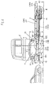
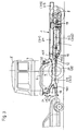
- the frame 1 according to the invention has front side member sections 2/3, 3 / 3, which - as can be clearly seen from FIG. 15 - are partially inclined to form a V-shaped installation area for the drive unit 4, as seen from the front (see also FIGS. 21, 22, 23).
- the front longitudinal beam sections 2/3, 3/3 are spaced further apart from one another on the upper chord side than on the lower chord side, which enables a deeper installation of the drive unit 4 and, as a result, a correspondingly lowered attachment of the cab 5 to the frame 1.
- the lowering of the front frame sections 2/3, 3/3 can be achieved in that the two frame side members 2, 3 - as can be seen from the illustrated exemplary embodiments - starting approximately in the area of the rear wall 7 of the cab and starting from the inside rear chassis area given frame height H5 are drawn obliquely downward and then extend at least in sections at the lower height level H4 as lowered longitudinal beam sections 2/3, 3/3 to the front.
- each of the two longitudinal beams 2, 3 is realized by a one-piece sheet-metal pressed part.
- a more complex construction is provided in the rear area of the frame.
- each of the two side members 2, 3 is dissolved approximately from the rear wall 7 of the driver's cab into an upper side member part 2/1, 3/1 and a lower side member part 2/2, 3/2, which runs essentially parallel to this.
- each longitudinal beam 2, 3 can each be designed either with the same cross-section and same cross-sectional height or different cross-section and different cross-sectional height, in the latter case the larger and larger cross-sectional part being the upper or lower part of the respective longitudinal beam 2, 3 can be.
- each longitudinal beam 2, 3 extends in a straight extension to the lowered front section 2/3, 3/3 of the same, ie the upper edges are aligned at the lower level H4, and extends rearward to in front of the (first, front) rear axle 8.
- the lower section 2/2, 3/2 of each divided longitudinal member 2, 3 is in a straight extension with the front lowered longitudinal member - Section 2/3, 3/3 formed in one piece and ends at the rear in front of the (first, front) rear axle 8.
- each side member 2, 3 can also either only up to the (first , front) rear axle 8 and there there are connecting elements 9, such as a plate or flanges, and connected to the rear of the chassis 10 via these.
- the chassis rear 10, consisting of the frame end piece and the rear axle (s) 8 can be at least largely preassembled as a module and then fastened to the chassis section in front of it by means of screw or rivet connections.
- FIGS. 13 and 14 shows - 10 different frame lengths and widths in the rear of the chassis and thus the best possible adaptation to different types of commercial vehicles or uses.
- the frame end piece is - as can be seen from FIGS.
- connection plate 23/3 which, when the pre-assembled chassis rear 10 is connected, on the ends of the side member parts 2/1, 2/2, 3/1, 3/2 given connection elements 9 comes / come and are connected to one another via screw or rivet connections.
- each longitudinal beam 2, 3 can also be extended beyond the rear axle arrangement to the rear of the vehicle (see FIGS. 2 to 3).
- the two parts of each frame side member 2, 3 are connected to one another by means of a bearing plate 11, which at the same time serves as a bearing element for the linkage elements of the rear axle (s) 8.
- each side member 2/1, 2/2 and 3/1, 3/2 of each side member 2, 3 are connected to one another without spacing, the upper side member part 2/1, 3 / 1 begins approximately at the height of the rear wall of the cab 7.
- each of the two longitudinal beams 2, 3 is provided with a vertical fork 12 at the rear end of its lower front section 2/3, 3/3, approximately in the area of the rear wall 7 of the cab, with the respective one being inclined section below the respective side member 2, 3 containing upper fork part 12/1 at frame height H5, the upper part 2/1 or 3/1 and on the lower fork part 12/2 the lower support part 2/2 or 3/2 of the respective side member 2 , 3 connects.
- the lower part 2/2 or 3/2 of a longitudinal beam 2, 3 is laid down so far that 2/1, 2/2 or 3/1 between the two longitudinal beam parts , 3/2 a spare wheel 13 transverse and / or other vehicle parts such as fuel tanks, compressed air storage containers, battery boxes, storage boxes and the like can be installed.
- vehicle parts 14 such as fuel or compressed air tanks, battery boxes, storage boxes and the like on the outside of the frame is possible because the fastening elements provided for this purpose, for.
- angle bracket 15 with its connecting leg 15/1 supported on both carrier parts 2/1, 2/2 or 3/1, 3/2 can be attached.
- the two parts 2/1, 2/2 or 3/1, 3/2 can be connected to one another via struts 24 to increase the frame strength .
- This section of the frame can either be realized by a welded construction or a pressed sheet metal part (as shown in FIG. 5).
- FIGS. 9 to 12 show different cross member constructions for the embodiments with longitudinal members 2, 3 which are divided into two in the middle area.
- straight or cranked cross members 23, 24, optionally provided with connecting flanges at the ends are provided, which are not connected to one another (see FIG. 9) or via an intermediate piece 25 (see FIG. 10) or in the middle (see FIG. 11) and to which the longitudinal beam parts are screwed, riveted or welded at the ends.
- the cross members 23, 24 are realized together with the struts 26 connecting them by means of a pressed sheet metal part, to which the longitudinal member parts are either screwed, riveted or welded.
- each of the two frame side members 2, 3 can have a vertical fork 17 at its front end region, on the lower fork part 17/2 at the front of which at least one in height H3 of a car bumper (see FIG. 1) arranged in frames -Longitudinal direction compliant energy absorber 18, a bumper 19 is supported.
- the cab 5, which can be tilted in the examples shown, is mounted on the frame 1 via bearing blocks 21, 22, which are covered by a front panel or second bumper 20.
- the front bearing blocks 21 are relatively short in height in the front end region of the respective upper fork part 17/1 of a frame side member 2, 3, while the rear Bearing blocks 22 are each arranged approximately at the fork region 12 or transition region between the non-lowered and the front lowered longitudinal beam section.
- each side member 2, 3 including the crotches 12, 17 can be realized as a one-piece sheet-metal pressed part or as a welded construction made of prefabricated sheet-metal pressed parts.
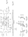
- two triangular wishbones 29, 30 and 31, 32 are provided spaced one above the other in approximately parallel transverse planes of the vehicle. These wishbones are articulated on the inner end of the frame 1 and the outer end, there up and down on the steering knuckle 33 and 34 of the respective wheel 27, 28 via a connecting member 35, 36 and 37, 38. These connecting members are preferably each placed from above on a corresponding plateau 39, 40 or 41, 42 of the steering knuckle 33 or 34 and attached to this.
- the two legs of each wishbone are designated 29/1, 29/2 or 30/1, 30/2 or 31/1, 31/2 or 32/1, 32/2.
- each of these claw joints consists of a central section penetrating the transverse bore of the respective bearing eye and end fastening eyes with front and rear plane-parallel contact surfaces and transverse through holes, the claw resting with its inner contact surfaces on the respective contact surface of the frame and is fastened in the area thereof by means of a screw connection penetrating a bore there and the transverse bore in the claw bearing eye.
- the two legs of the lower wishbones 30, 32 are each longer than the legs of the upper wishbones 29, 31.
- the distance between the bearing eyes of the lower wishbones 30, 32 is greater than that of the bearing eyes of the upper wishbone arm 29, 31.
- Each upper wishbone arm 29, 31 projects with its inner end bearing eyes 29/3, 29/4 or 31/3, 31/4 in this outside on the front side member section 2/3, 3/3 given recesses 44 (see in particular Fig. 21), the side surfaces 44/1, 44/2 (see Fig. 19) have a larger clearance than the side surfaces of the bearing eyes of the upper wishbones 29, 31.
- the depressions 44 can be formed by pockets which are pressed off-center from the outside into an inclined web section of the front longitudinal beam section 2/3, 3/3 near the rigid corner region with the lower flange.
- the supports 44/3, 44/4 on both sides of such a pocket 44 on said web section for the associated claw joint 43 are - as can be seen clearly from FIGS. 19 and 21 - appropriately calibrated on the outside on projections pressed outwards in the web.
- the depressions 44 for receiving the bearing eyes 29/3, 29/4; 31/3, 31/4 of the upper wishbone arm 29, 31 also each by the space between two on the web of each front side member section 2/3, 3/3 correspondingly pressed out from the inside outward projections on which outside the contact surfaces 44/3, 44/4 are correspondingly calibrated for the respective claw joint 43.
- two cross members 45 connecting the two front longitudinal member sections 2/3, 3/3, viewed from the front are drawn downward approximately V-shaped, as can be seen well from FIGS. 15 and 24 , 46 provided.
- Each of these two V-shaped cross members 45, 46 has an open UT cross-section, the base being formed by an U-profile open to the outside, as shown in FIG. 17, on the two side legs 45/1, 45 / 2 or 46/1, 46/2 protruding on the outside, parallel to the U-profile base 45/3 or 46/3, the support and the connection of the claw joints 43 of the lower wishbones 30, 32 serving T-bars 45 / Connect 4, 45/5 or 46/4, 46/5.
- the lower wishbones 30, 32 with their bearing eyes 30/3, 30/4 and 32/3, 32/4 each protrude into the open U-profile space of the two cross members 45, 46 at the lower end of their oblique legs Height of the horizontal section in (see Fig. 15 and 16).
- the connection points for the associated claw joints 43 are provided at the lower end of the oblique legs 45/7, 45/8 or 46/7, 46/8 on oblique T-web sections, which can be seen well from FIG. 15.
- the clear width of the open U-profile of the two cross members, given by the side walls 45/1, 45/2 or 46/1, 46/2, is (as can be seen in FIG. 16) somewhat larger than the distance between the side surfaces on the respective bearing eye 30/3, 30/4 or 32/3, 32/4.
- the front cross member 45 viewed forward in the direction of travel can be stabilized via longitudinal struts 51, 52, as can be seen in FIG are supported articulated.
- the two cross members 45, 46 can, as shown, each be realized by a one-piece sheet-metal pressed part or, in each case, two sheet-metal pressed parts that are mirror-symmetrical to the longitudinal direction of the vehicle and welded together along the line of symmetry.
- independent suspension is suitable for both non-driven and driven, steered front wheels 27, 28.
- this type of independent suspension also allows a particularly favorable arrangement of suspension elements, in particular an air suspension, which will be discussed in more detail below.
- an air spring 54 combined with a shock absorber 53 is used to implement air suspension in the front axle area for each front wheel 27, 28, the air spring 54 being combined at the top with the shock absorber 53, which is at its lower end on each lower (possibly also upper) wishbone 30 and 32 is supported at the transition area by its two legs.
- the relevant connection points are tightened at 55 in FIGS. 18 and 24.
- the air spring 54 is supported and fastened at the top to a spring bracket 56, which is connected in a special way to the front longitudinal member section 2/3 or 3/3. 18, 19 and in particular 22, each front longitudinal beam section 2/3, 3/3 is located locally on its web between the pockets 44 for the articulation of the upper wishbones 29, 31 pulled upwards and outwards, see the relevant section 57, and provided with an indentation 58.
- the spring bracket 56 with its correspondingly adapted connecting area 56/1 is attached and fastened, in particular welded, to the indentation 58 and the raised section 57.
- axle center gear 59 screwed to the drive unit 4 saves mounting brackets on the frame 1.
- axle center gear 59 can also be attached to the two cross members 45, 46, which enables the same to be mounted differently, depending on the drive unit.
Landscapes
- Engineering & Computer Science (AREA)
- Mechanical Engineering (AREA)
- Chemical & Material Sciences (AREA)
- Combustion & Propulsion (AREA)
- Transportation (AREA)
- Body Structure For Vehicles (AREA)
- Steering Control In Accordance With Driving Conditions (AREA)
- Automatic Cycles, And Cycles In General (AREA)
Applications Claiming Priority (2)
| Application Number | Priority Date | Filing Date | Title |
|---|---|---|---|
| DE4234138A DE4234138A1 (de) | 1992-10-09 | 1992-10-09 | Nutzfahrzeug, insbesondere Frontlenker-Lastkraftwagen |
| DE4234138 | 1992-10-09 |
Publications (2)
| Publication Number | Publication Date |
|---|---|
| EP0591719A1 true EP0591719A1 (fr) | 1994-04-13 |
| EP0591719B1 EP0591719B1 (fr) | 1996-03-13 |
Family
ID=6470122
Family Applications (1)
| Application Number | Title | Priority Date | Filing Date |
|---|---|---|---|
| EP93114791A Expired - Lifetime EP0591719B1 (fr) | 1992-10-09 | 1993-09-15 | Véhicule utilitaire, notamment un camion à cabine avancée |
Country Status (3)
| Country | Link |
|---|---|
| EP (1) | EP0591719B1 (fr) |
| AT (1) | ATE135313T1 (fr) |
| DE (2) | DE4234138A1 (fr) |
Cited By (1)
| Publication number | Priority date | Publication date | Assignee | Title |
|---|---|---|---|---|
| EP1241077A1 (fr) * | 2001-03-16 | 2002-09-18 | IVECO FIAT S.p.A. | Camion à plancher de cabine surbaissé et plat |
Families Citing this family (1)
| Publication number | Priority date | Publication date | Assignee | Title |
|---|---|---|---|---|
| DE10152184A1 (de) | 2001-10-23 | 2003-04-30 | Daimler Chrysler Ag | Tragstruktur für ein Nutzfahrzeug |
Citations (11)
| Publication number | Priority date | Publication date | Assignee | Title |
|---|---|---|---|---|
| US1894602A (en) * | 1931-03-09 | 1933-01-17 | Peerless Motor Car Corp | Vehicle frame |
| US2129232A (en) * | 1934-12-17 | 1938-09-06 | Packard Motor Car Co | Motor vehicle |
| CH301316A (de) * | 1952-04-18 | 1954-08-31 | Automobilove Z Nationalunterne | Motorfahrzeug mit wenigstens einer Treibachse mit einzeln geführten Rädern. |
| US3052313A (en) * | 1959-07-15 | 1962-09-04 | Ford Motor Co | Vehicular power plant |
| BE647435A (fr) * | 1964-04-06 | 1964-08-17 | ||
| FR2214281A5 (fr) * | 1973-01-11 | 1974-08-09 | Benalu | |
| FR2240138A1 (en) * | 1973-08-11 | 1975-03-07 | Wackenhut Ernst | Lorry loading floor support structure - has inclined longitudinal supports which can be detached from the chassis |
| FR2308539A1 (fr) * | 1975-04-26 | 1976-11-19 | British Leyland Uk Ltd | Chassis de vehicule automobile |
| DE3312446A1 (de) * | 1983-04-07 | 1984-10-18 | Ackermann-Fruehauf Corporation & Co Ohg, 5600 Wuppertal | Lastkraftwagen |
| DE4019796A1 (de) * | 1990-06-21 | 1992-01-02 | Bayerische Motoren Werke Ag | Achse fuer ein kraftfahrzeug |
| FR2667839A1 (fr) * | 1990-10-16 | 1992-04-17 | Man Nutzfahrzeuge Ag | Vehicule de livraison notamment vehicule destine a la circulation urbaine. |
Family Cites Families (5)
| Publication number | Priority date | Publication date | Assignee | Title |
|---|---|---|---|---|
| DE883399C (de) * | 1951-07-27 | 1953-07-16 | Daimler Benz Ag | Fahrgestell, insbesondere fuer Kraftwagen |
| DE1430191A1 (de) * | 1962-12-13 | 1969-05-08 | Maschf Augsburg Nuernberg Ag | Bodenkonstruktion fuer die Aufbauten von Lastkraftwagen |
| DE2714017A1 (de) * | 1977-03-30 | 1978-10-12 | Magirus Deutz Ag | Fahrgestellrahmen fuer omnibusse |
| JPH0735121B2 (ja) * | 1987-04-14 | 1995-04-19 | マツダ株式会社 | 自動車のサブフレ−ム構造 |
| DE3827923A1 (de) * | 1988-08-17 | 1989-10-05 | Daimler Benz Ag | Rahmen fuer kraftfahrzeuge |
-
1992
- 1992-10-09 DE DE4234138A patent/DE4234138A1/de not_active Ceased
-
1993
- 1993-09-15 DE DE59301876T patent/DE59301876D1/de not_active Expired - Fee Related
- 1993-09-15 EP EP93114791A patent/EP0591719B1/fr not_active Expired - Lifetime
- 1993-09-15 AT AT93114791T patent/ATE135313T1/de not_active IP Right Cessation
Patent Citations (11)
| Publication number | Priority date | Publication date | Assignee | Title |
|---|---|---|---|---|
| US1894602A (en) * | 1931-03-09 | 1933-01-17 | Peerless Motor Car Corp | Vehicle frame |
| US2129232A (en) * | 1934-12-17 | 1938-09-06 | Packard Motor Car Co | Motor vehicle |
| CH301316A (de) * | 1952-04-18 | 1954-08-31 | Automobilove Z Nationalunterne | Motorfahrzeug mit wenigstens einer Treibachse mit einzeln geführten Rädern. |
| US3052313A (en) * | 1959-07-15 | 1962-09-04 | Ford Motor Co | Vehicular power plant |
| BE647435A (fr) * | 1964-04-06 | 1964-08-17 | ||
| FR2214281A5 (fr) * | 1973-01-11 | 1974-08-09 | Benalu | |
| FR2240138A1 (en) * | 1973-08-11 | 1975-03-07 | Wackenhut Ernst | Lorry loading floor support structure - has inclined longitudinal supports which can be detached from the chassis |
| FR2308539A1 (fr) * | 1975-04-26 | 1976-11-19 | British Leyland Uk Ltd | Chassis de vehicule automobile |
| DE3312446A1 (de) * | 1983-04-07 | 1984-10-18 | Ackermann-Fruehauf Corporation & Co Ohg, 5600 Wuppertal | Lastkraftwagen |
| DE4019796A1 (de) * | 1990-06-21 | 1992-01-02 | Bayerische Motoren Werke Ag | Achse fuer ein kraftfahrzeug |
| FR2667839A1 (fr) * | 1990-10-16 | 1992-04-17 | Man Nutzfahrzeuge Ag | Vehicule de livraison notamment vehicule destine a la circulation urbaine. |
Cited By (1)
| Publication number | Priority date | Publication date | Assignee | Title |
|---|---|---|---|---|
| EP1241077A1 (fr) * | 2001-03-16 | 2002-09-18 | IVECO FIAT S.p.A. | Camion à plancher de cabine surbaissé et plat |
Also Published As
| Publication number | Publication date |
|---|---|
| DE59301876D1 (de) | 1996-04-18 |
| DE4234138A1 (de) | 1994-04-14 |
| ATE135313T1 (de) | 1996-03-15 |
| EP0591719B1 (fr) | 1996-03-13 |
Similar Documents
| Publication | Publication Date | Title |
|---|---|---|
| EP0940272B1 (fr) | Chassis pour un camion à cabine avancée | |
| DE4234120A1 (de) | Nutzfahrzeug, insbesondere Frontlenker-Lastkraftwagen | |
| EP0591726B1 (fr) | Véhicule utilitaire, en particulier camion avec cabine à l'avant | |
| EP0940320B1 (fr) | Chassis pour véhicule utilitaire lourd | |
| DE10036396B4 (de) | Fahrschemel-Modul für ein Kraftfahrzeug | |
| EP0940319A2 (fr) | Chassis d'un véhicule utilitaire lourd | |
| WO2004048181A1 (fr) | Structure avant de vehicule automobile | |
| EP0591722B1 (fr) | Véhicule utilitaire, en particulier camion avec cabine à l'avant | |
| DE4234143A1 (de) | Nutzfahrzeug, insbesondere Frontlenker-Lastkraftwagen mit Rundum-Knautschzonen | |
| EP0591719B1 (fr) | Véhicule utilitaire, notamment un camion à cabine avancée | |
| EP0940322B1 (fr) | Chassis pour véhicule utilitaire lourd | |
| EP0591717B1 (fr) | Véhicule utilitaire, notamment un camion à cabine avancée | |
| EP0591727B1 (fr) | Véhicule utilitaire, en particulier camion avec cabine à l'avant | |
| DE19537573C2 (de) | Allrad-Kfz | |
| EP0940324A1 (fr) | Chassis pour véhicule utilitaire lourd | |
| EP0940325A1 (fr) | Chassis pour véhicule utilitaire lourd | |
| WO2005066010A1 (fr) | Chassis de vehicule a moteur | |
| DE19809268A1 (de) | Fahrgestell eines schweren Nutzfahrzeuges | |
| DE10309628B4 (de) | Tragestruktur eines Fahrzeugs | |
| EP0591720B1 (fr) | Véhicule utilitaire, notamment camion à cabine avancée | |
| DE4234100A1 (de) | Nutzfahrzeug, insbesondere Frontlenker-Lastkraftwagen | |
| DE19809203A1 (de) | Fahrgestell eines schweren Nutzfahrzeuges | |
| DE102006008008A1 (de) | Frontstruktur eines Kraftfahrzeugs |
Legal Events
| Date | Code | Title | Description |
|---|---|---|---|
| PUAI | Public reference made under article 153(3) epc to a published international application that has entered the european phase |
Free format text: ORIGINAL CODE: 0009012 |
|
| AK | Designated contracting states |
Kind code of ref document: A1 Designated state(s): AT DE FR GB IT NL SE |
|
| 17P | Request for examination filed |
Effective date: 19940223 |
|
| 17Q | First examination report despatched |
Effective date: 19940623 |
|
| GRAA | (expected) grant |
Free format text: ORIGINAL CODE: 0009210 |
|
| ITF | It: translation for a ep patent filed | ||
| AK | Designated contracting states |
Kind code of ref document: B1 Designated state(s): AT DE FR GB IT NL SE |
|
| REF | Corresponds to: |
Ref document number: 135313 Country of ref document: AT Date of ref document: 19960315 Kind code of ref document: T |
|
| ET | Fr: translation filed | ||
| REF | Corresponds to: |
Ref document number: 59301876 Country of ref document: DE Date of ref document: 19960418 |
|
| GBT | Gb: translation of ep patent filed (gb section 77(6)(a)/1977) |
Effective date: 19960329 |
|
| PLBE | No opposition filed within time limit |
Free format text: ORIGINAL CODE: 0009261 |
|
| 26N | No opposition filed | ||
| PGFP | Annual fee paid to national office [announced via postgrant information from national office to epo] |
Ref country code: GB Payment date: 19980814 Year of fee payment: 6 |
|
| PGFP | Annual fee paid to national office [announced via postgrant information from national office to epo] |
Ref country code: FR Payment date: 19980821 Year of fee payment: 6 Ref country code: DE Payment date: 19980821 Year of fee payment: 6 |
|
| PGFP | Annual fee paid to national office [announced via postgrant information from national office to epo] |
Ref country code: SE Payment date: 19980824 Year of fee payment: 6 Ref country code: AT Payment date: 19980824 Year of fee payment: 6 |
|
| PGFP | Annual fee paid to national office [announced via postgrant information from national office to epo] |
Ref country code: NL Payment date: 19980827 Year of fee payment: 6 |
|
| PG25 | Lapsed in a contracting state [announced via postgrant information from national office to epo] |
Ref country code: GB Free format text: LAPSE BECAUSE OF NON-PAYMENT OF DUE FEES Effective date: 19990915 Ref country code: AT Free format text: LAPSE BECAUSE OF NON-PAYMENT OF DUE FEES Effective date: 19990915 |
|
| PG25 | Lapsed in a contracting state [announced via postgrant information from national office to epo] |
Ref country code: SE Free format text: THE PATENT HAS BEEN ANNULLED BY A DECISION OF A NATIONAL AUTHORITY Effective date: 19990929 |
|
| PG25 | Lapsed in a contracting state [announced via postgrant information from national office to epo] |
Ref country code: NL Free format text: LAPSE BECAUSE OF NON-PAYMENT OF DUE FEES Effective date: 20000401 |
|
| GBPC | Gb: european patent ceased through non-payment of renewal fee |
Effective date: 19990915 |
|
| EUG | Se: european patent has lapsed |
Ref document number: 93114791.2 |
|
| PG25 | Lapsed in a contracting state [announced via postgrant information from national office to epo] |
Ref country code: FR Free format text: LAPSE BECAUSE OF NON-PAYMENT OF DUE FEES Effective date: 20000531 |
|
| NLV4 | Nl: lapsed or anulled due to non-payment of the annual fee |
Effective date: 20000401 |
|
| PG25 | Lapsed in a contracting state [announced via postgrant information from national office to epo] |
Ref country code: DE Free format text: LAPSE BECAUSE OF NON-PAYMENT OF DUE FEES Effective date: 20000701 |
|
| REG | Reference to a national code |
Ref country code: FR Ref legal event code: ST |
|
| PG25 | Lapsed in a contracting state [announced via postgrant information from national office to epo] |
Ref country code: IT Free format text: LAPSE BECAUSE OF NON-PAYMENT OF DUE FEES;WARNING: LAPSES OF ITALIAN PATENTS WITH EFFECTIVE DATE BEFORE 2007 MAY HAVE OCCURRED AT ANY TIME BEFORE 2007. THE CORRECT EFFECTIVE DATE MAY BE DIFFERENT FROM THE ONE RECORDED. Effective date: 20050915 |