EP0591790A1 - Procédé et dispositif de carbonisation-combustion à commande de pression - Google Patents
Procédé et dispositif de carbonisation-combustion à commande de pression Download PDFInfo
- Publication number
- EP0591790A1 EP0591790A1 EP93115463A EP93115463A EP0591790A1 EP 0591790 A1 EP0591790 A1 EP 0591790A1 EP 93115463 A EP93115463 A EP 93115463A EP 93115463 A EP93115463 A EP 93115463A EP 0591790 A1 EP0591790 A1 EP 0591790A1
- Authority
- EP
- European Patent Office
- Prior art keywords
- pressure
- gas
- speed
- gas compressor
- smoldering
- Prior art date
- Legal status (The legal status is an assumption and is not a legal conclusion. Google has not performed a legal analysis and makes no representation as to the accuracy of the status listed.)
- Granted
Links
Images


Classifications
-
- F—MECHANICAL ENGINEERING; LIGHTING; HEATING; WEAPONS; BLASTING
- F23—COMBUSTION APPARATUS; COMBUSTION PROCESSES
- F23N—REGULATING OR CONTROLLING COMBUSTION
- F23N1/00—Regulating fuel supply
- F23N1/06—Regulating fuel supply conjointly with draught
-
- C—CHEMISTRY; METALLURGY
- C10—PETROLEUM, GAS OR COKE INDUSTRIES; TECHNICAL GASES CONTAINING CARBON MONOXIDE; FUELS; LUBRICANTS; PEAT
- C10B—DESTRUCTIVE DISTILLATION OF CARBONACEOUS MATERIALS FOR PRODUCTION OF GAS, COKE, TAR, OR SIMILAR MATERIALS
- C10B53/00—Destructive distillation, specially adapted for particular solid raw materials or solid raw materials in special form
-
- F—MECHANICAL ENGINEERING; LIGHTING; HEATING; WEAPONS; BLASTING
- F23—COMBUSTION APPARATUS; COMBUSTION PROCESSES
- F23N—REGULATING OR CONTROLLING COMBUSTION
- F23N2233/00—Ventilators
- F23N2233/02—Ventilators in stacks
- F23N2233/04—Ventilators in stacks with variable speed
-
- Y—GENERAL TAGGING OF NEW TECHNOLOGICAL DEVELOPMENTS; GENERAL TAGGING OF CROSS-SECTIONAL TECHNOLOGIES SPANNING OVER SEVERAL SECTIONS OF THE IPC; TECHNICAL SUBJECTS COVERED BY FORMER USPC CROSS-REFERENCE ART COLLECTIONS [XRACs] AND DIGESTS
- Y02—TECHNOLOGIES OR APPLICATIONS FOR MITIGATION OR ADAPTATION AGAINST CLIMATE CHANGE
- Y02E—REDUCTION OF GREENHOUSE GAS [GHG] EMISSIONS, RELATED TO ENERGY GENERATION, TRANSMISSION OR DISTRIBUTION
- Y02E50/00—Technologies for the production of fuel of non-fossil origin
- Y02E50/10—Biofuels, e.g. bio-diesel
Definitions
- the invention relates to a smoldering process, in which the smoldering gas generated by a pyrolysis drum is passed into the burner of a combustion chamber and the flue gas resulting there as a result of combustion is supplied to an outlet via a cooling device and a gas compressor, the gas compressor being used for the Pressure in the gas path between the pyrolysis drum and the gas compressor is affected.
- the invention further relates to a smoldering and burning plant which works according to this method. The process and the plant are used for thermal waste disposal.
- the so-called smoldering process has become known in the field of waste disposal.
- the method and a plant for thermal waste disposal operating according to it are described, for example, in EP-A-0 302 310 and in DE-A-38 30 153.
- the essential components of the plant for thermal waste disposal using the smoldering-firing process include a pyrolysis reactor and a high-temperature combustion chamber.
- the pyrolysis reactor converts the waste into carbonization gas and pyrolysis residue.
- the carbonization gas and the pyrolysis residue are then fed to the burner of the high-temperature combustion chamber after suitable processing.
- Molten slag is formed here, which can be removed via a fume hood and which, after cooling, is in a glazed form.
- the resulting flue gas is fed to a chimney as an outlet via a flue gas line.
- a flue gas pipe In this flue gas pipe are in particular a heat recovery steam generator installed as a cooling device, a dust filter system and a flue gas cleaning system.
- a gas compressor in the flue gas line, which is arranged directly at the outlet of the flue gas cleaning system and can be designed as a suction fan.
- the built-in gas compressor serves to maintain a vacuum, albeit low, in the pyrolysis drum. This negative pressure prevents carbonization gas from escaping to the outside through the ring seals of the pyrolysis drum.
- the gas compressor or the suction fan may hardly run at a constant speed, since a fluctuating gas production creates a fluctuating pressure in the gas path between the pyrolysis drum and the gas compressor.
- Such a discontinuous behavior of the gas pressure is undesirable since it could, under certain circumstances - even if only briefly - lead to the ambient pressure being exceeded and thus to the escape of flue gas or to excessive vacuum in the said flue gas path.
- the object of the invention is to provide measures in the above-mentioned smoldering-burning method and in the above-mentioned smoldering-burning system which enable the pressure to be checked, even if the gas production in the smoldering drum fluctuates.
- this object is achieved according to the invention in that at a pressure in the gas path which is lower than the pressure in the environment, the speed of the gas compressor is guided as a function of the pressure in the gas path in such a way that when the pressure is reduced the speed is reduced.
- the invention is thus based on the consideration that at least in a pressure range in which the pressure in the gas path is lower than the pressure in the environment, a large gas production in the smoldering drum due to a high speed, a low gas production - which go to zero can - on the other hand can be managed by a low speed of the gas compressor. If the pressure in said gas path should rise above a pressure that is above a maximum pressure or even above the ambient pressure, for example as a result of excessive waste moisture and thus an excessively produced amount of carbonization gas, then further measures can be provided, which are explained in more detail below.
- pressure regulation via the speed is provided.
- This development is characterized in that the pressure in said gas path is kept at a predetermined target value, which is lower than the pressure in the environment.
- measures are preferably provided with which the pressure in said gas path is always kept below the pressure in the environment.
- the speed of the gas compressor is significantly reduced or even set to zero when a predetermined minimum value of the pressure in said gas path is reached.
- a further gas compressor is arranged in parallel, but preferably in series with the gas compressor, and that the speed of the further gas compressor is guided in dependence on the pressure in said gas path in such a way that the speed decreases when the pressure is reduced becomes.
- the procedure When operating this further gas compressor, the procedure will be analogous to that of the first gas compressor. Accordingly, the speed of the further gas compressor can be guided in the same way with respect to the desired value, ambient pressure, maximum value and / or minimum value as the speed of the first-mentioned gas compressor.
- redundant speed control will be provided. This is characterized in that the speed of the gas compressor and independently of it the speed of the further gas compressor are in each case dependent on the pressure in the pyrolysis drum and the pressure in the further pyrolysis drum.
- the gas production in the two pyrolystrums can differ in quantity.
- the preferred procedure is to select the higher of the two pressures in the pyrolysis drums to control the speed.
- the higher pressure leads to a higher speed and this in turn leads to a faster reduction in pressure.
- the stated object is achieved according to the invention with respect to the smoldering-burning system in that a control device is provided which guides the speed of the gas compressor as a function of the pressure in the said gas path in such a way that the speed is reduced when the pressure is reduced.
- control device can comprise means which have a predetermined relationship between the measured value supplied for the pressure and the manipulated variable for ensure the speed.
- This predetermined relation can be in the form of a table or a diagram and can be stored in the control device.
- control device is preceded by a controller, which, in addition to the determined measured pressure value, also has a predetermined setpoint for the pressure in the gas path.
- This control circuit ensures that - at least in the long term - the pressure in the gas path is held at the predetermined setpoint.
- a system which accomplishes this is characterized in that a comparator is provided which compares a measured value for the pressure in the gas path with a predetermined maximum value and which, when the maximum value is exceeded, supplies an additional signal to the control device such that the speed of the Gas compressor is significantly increased. In this way, behavior with a sharply kinking or bending control characteristic can be generated.
- a comparator which compares a determined measured value for the pressure in the gas path with a predetermined minimum value and which, when the value falls below the minimum value, provides an additional input signal to the control device in such a way that the speed of the gas compressor is significantly reduced or set to zero.
- a further gas compressor is arranged in the gas path.
- This can be arranged in parallel, but preferably in series with the gas compressor already mentioned.
- a further control device is provided, which also performs the speed of the further gas compressor - regardless of the speed of the first-mentioned gas compressor - as a function of the pressure in the gas path in such a way that when the pressure is reduced the The speed of the further gas compressor is reduced.
- the procedure should be as described above for the first-mentioned control device.
- the further control device should therefore preferably be preceded by the same components as the first-mentioned control device.
- a further pyrolysis drum can be provided for capacity or approval reasons. This is preferably connected to the burner of the existing combustion chamber, so that the two pyrolysis drums work in parallel.
- At least one pressure meter can be provided for pressure measurement in each of the two pyrolysis drums, preferably on the respective outlet housing.
- the procedure can be such that the control device and the further control device are each connected on the input side to a first and a second pressure meter, the first pressure meter measuring the pressure in the pyrolysis drum and the second pressure meter measuring the pressure in the further pyrolysis drum.
- control device and the further control device each contain a discriminator which forwards the higher pressure value to control the speed in question.
- a flue gas cleaning system in particular a DeNO x cleaner, can be connected between the gas compressor and the further gas compressor.
- the smoldering plant comprises a smoldering or pyrolysis drum 2, the waste a is fed.
- the pyrolysis drum 2 produces carbonization gas s, which is fed from its outlet housing 4 to the burner 6 of a high-temperature combustion chamber 8 with slag discharge.
- the flue gas r arising there as a result of combustion is fed via a cooling device 10, in the present case a waste heat boiler, to a flue gas cleaning device 12.
- a cooling device 10 in the present case a waste heat boiler
- a flue gas cleaning device 12 This can be, in particular, a wet flue gas cleaning system with a dust filter system.
- the cleaned flue gas is then placed in a DeNO x device 14, where it is largely freed of nitrogen oxides.
- a blower or gas compressor 16 is provided at the outlet of the DeNO x device 14 and is driven by an electric motor 18.
- the flue gas line then leads to an outlet in the form of a chimney 20.
- the pressure p in the gas path between the pyrolysis drum 2 and the gas compressor 16 is influenced by the gas compressor 16.
- the procedure is such that the speed n of the gas compressor 16 is guided as a function of the pressure p in the gas path between the pyrolysis drum 2 and the gas compressor 16 such that the speed n is reduced when the pressure p is reduced.
- the pressure p is measured with the aid of a pressure sensor or pressure meter 22 in the pyrolysis drum 2, preferably in its outlet housing 4.
- the pressure measured value p is fed to a control device 24, which is provided for actuating the electric motor 18 as an actuator.
- This type of control of the speed n is provided at a pressure p in said gas path which is lower than the pressure p o in the environment. If the pressure p approaches this ambient pressure p o , this type of speed control can be replaced by another guide or a safety measure.
- the speed control can be expanded to a speed control.
- the controller 24 is preceded by a controller 26 to which the actual pressure value p and a pressure setpoint value p * for the purpose of Comparison are activated.
- the pressure p in said gas path can be kept at the predetermined setpoint p *, this setpoint p * being lower than the pressure p o in the environment.
- FIG. 3 shows a variation of the circuit of FIG. 1 which ensures that the pressure p in said gas path is always kept below a maximum limit value p max .
- a correction value ⁇ p is applied so that the speed is significantly increased at higher pressure p and is therefore sucked in more strongly.
- the actual value of the pressure p and the additional signal ⁇ p are fed to an adder 28, which is assigned to the control device 24.
- the correction value or the additional signal ⁇ p is taken from a function generator 30 which is connected downstream of a comparator 32.
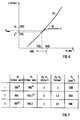
- the comparator 32 compares the measured value p determined for the pressure in the gas path with the predetermined maximum value p max ; if the maximum value p max is exceeded, it outputs the additional signal ⁇ p to the control device 24. With the help of the function generator 30, this is done in such a way that the speed n of the gas compressor 16 is significantly increased. This boils down to the fact that the connection in FIG. 6 does not apply to the solid curve shape 34 but to the dashed curve shape 36.
- FIG. 4 shows an embodiment in which it is ensured that an emergency measure is taken when the pressure falls below a minimum value p min such that the speed n of the gas compressor 16 is greatly reduced or even set to zero in order to allow an increase in pressure .
- a comparator 40 is provided here, which has the determined measured value p for the pressure in the gas path with the predetermined minimum value p min compares. If the minimum value p min is undershot, it activates a function generator 42 which supplies an input signal ⁇ z, which is additional to the pressure signal p, to a subtraction element 44, which is assigned to the control device 24. This is done in such a way that the speed n of the gas compressor 16 - as already mentioned - is significantly reduced or even set to zero.
- a further pyrolysis or carbonization drum 52 is provided here, the carbonization line of which is also connected to the burner 6 of the combustion chamber 8.
- a further gas compressor 54 with a drive motor 56 is arranged between the flue gas cleaning device 12 and the DeNO x device 14.
- the two gas compressors 16, 54 are therefore connected in series with one another. Redundancy is ensured by the arrangement of the two fans or gas compressors 16, 56.
- two pressure gauges 58, 60 and 62, 64 are provided in each of the two pyrolysis drums 2, 52.
- the pressure gauges 58, 60 are arranged on the outlet housing 6 and the pressure gauges 62, 64 are arranged on the outlet housing 66. They could also be installed in the carbonization line.
- Two control devices 70 and 72 are provided for controlling the speed n I of the first fan 16 and the speed n II of the second fan 54.
- the control device 70 is connected on the input side to the pressure gauge 58 on the pyrolysis drum 2 and to the pressure gauge 62 on the pyrolysis drum 52.
- the further control device 72 is connected on the input side to the pressure gauge 60 on the first pyrolysis drum 2 and to the pressure gauge 64 on the further pyrolysis drum 52.
- Each of the two control devices 70, 72 contains a discriminator 74 or 76, which forwards the respectively higher pressure value to guide the relevant speed n I or n II .
- the two pyrolysis drums 2, 52 generate carbonization gas s during operation. In the event of faults in the system, gas production cannot now be interrupted spontaneously; it has been shown that, after switching off, about 0.5 to 1 hour uncontrollable carbonization gas s is generated.
- the two gas compressors 16, 54 suck the carbonization gas s from the pyrolysis drums 2, 52 in normal operation and also in the event of a fault, specifically via the combustion chamber 8, the cooling device 10 in the form of the waste heat boiler, the flue gas cleaning device 12 and the DeNO x device 14 , and convey the flue gas r to the chimney 20.
- the operation is again designed so that with a large gas production and thus at a high pressure p1 to p4 in the pyrolysis drums 2, 52 a high speed n I , n II sets, whereas with a low gas production a low speed n I , n II is set.
- the system shown is insensitive, in particular, to a conceivable disturbance, which can be described by the terms "low gas production” and "high speed".
- a low gas production can occur with a small task of waste a, and an excessively high speed n I or n II can occur in the event of a fault in the measured value recording, ie in one of the pressure gauges 58 to 64, or in the event of a fault in the measured value processing in one of the control devices 70, 72 arise.
- the high speed - without the countermeasures taken here - creates a high suction or negative pressure on the gas path from the pyrolysis drums 2, 52 to the gas compressors 16, 54 with a small amount of gas.
- the components located here, such as flue gas cleaning containers 12, electrostatic filters, waste heat boilers 10, are not designed for this negative pressure and can be destroyed by implosion.
- the circuit arrangement shown is therefore safe from interference of this type, so that no smoldering or flue gas s, r can escape to the outside.
- a pressure sensor 58, 62 and 60, 64 is arranged for each blower 14, 54 on both pyrolysis drums 2, 52, as mentioned.
- the higher of the two absolute pressure values present is always the reference variable for setting the speed n I or n II .
- the guidance takes place, for example, by regulation according to FIG. 6, curve 34 or 36.
- Both fans 16, 54 are operated even when a pyrolysis drum 2, 52 is at a standstill.
- the same malfunction can also be mastered when it is at a standstill, for example when repairing a pyrolysis drum 2, 52.
Landscapes
- Engineering & Computer Science (AREA)
- Chemical & Material Sciences (AREA)
- Oil, Petroleum & Natural Gas (AREA)
- Combustion & Propulsion (AREA)
- Mechanical Engineering (AREA)
- General Engineering & Computer Science (AREA)
- Materials Engineering (AREA)
- Organic Chemistry (AREA)
- Gasification And Melting Of Waste (AREA)
- Incineration Of Waste (AREA)
- Processing Of Solid Wastes (AREA)
- Carbon And Carbon Compounds (AREA)
- Control Of Fluid Pressure (AREA)
- Coke Industry (AREA)
- Air-Conditioning For Vehicles (AREA)
- Control Of Steam Boilers And Waste-Gas Boilers (AREA)
- Output Control And Ontrol Of Special Type Engine (AREA)
Applications Claiming Priority (2)
| Application Number | Priority Date | Filing Date | Title |
|---|---|---|---|
| DE4234163A DE4234163A1 (de) | 1992-10-09 | 1992-10-09 | Schwel-Brenn-Verfahren sowie Schwel-Brenn-Anlage mit Drucksteuerung |
| DE4234163 | 1992-10-09 |
Publications (2)
| Publication Number | Publication Date |
|---|---|
| EP0591790A1 true EP0591790A1 (fr) | 1994-04-13 |
| EP0591790B1 EP0591790B1 (fr) | 1998-03-18 |
Family
ID=6470133
Family Applications (1)
| Application Number | Title | Priority Date | Filing Date |
|---|---|---|---|
| EP93115463A Expired - Lifetime EP0591790B1 (fr) | 1992-10-09 | 1993-09-24 | Procédé et dispositif de carbonisation-combustion à commande de pression |
Country Status (15)
| Country | Link |
|---|---|
| US (1) | US5497712A (fr) |
| EP (1) | EP0591790B1 (fr) |
| JP (1) | JPH07305067A (fr) |
| KR (1) | KR940009318A (fr) |
| CN (1) | CN1039026C (fr) |
| AT (1) | ATE164181T1 (fr) |
| CA (1) | CA2107943A1 (fr) |
| CZ (1) | CZ211093A3 (fr) |
| DE (2) | DE4234163A1 (fr) |
| DK (1) | DK0591790T3 (fr) |
| ES (1) | ES2113981T3 (fr) |
| HU (1) | HU216524B (fr) |
| PL (1) | PL175547B1 (fr) |
| RU (1) | RU2116328C1 (fr) |
| SK (1) | SK110193A3 (fr) |
Families Citing this family (6)
| Publication number | Priority date | Publication date | Assignee | Title |
|---|---|---|---|---|
| US6199492B1 (en) * | 1992-02-26 | 2001-03-13 | KüNSTLER JOHANN HANS | Process for melting down combustion residues into slag |
| US6182584B1 (en) * | 1999-11-23 | 2001-02-06 | Environmental Solutions & Technology, Inc. | Integrated control and destructive distillation of carbonaceous waste |
| KR101385101B1 (ko) * | 2008-06-27 | 2014-04-15 | 동부대우전자 주식회사 | 가스식 건조기의 밸브 제어 방법 |
| UA107477C2 (uk) * | 2012-06-15 | 2015-01-12 | Yevhen Oleksiiovych Danilin | Установка та спосіб теплового знешкоджування та утилізації тепла димових газів, які відходять від паливоспалювальних агрегатів, та система керування їх роботою |
| PH12021552827A1 (en) * | 2019-05-08 | 2022-10-03 | Kinsei Sangyo Co Ltd | Dry distillation and gasification incineration processing device |
| CN115307148B (zh) * | 2022-07-29 | 2024-12-31 | 昆明理工大学 | 热解气化燃烧协同电滤耦合电催化尾气净化热解装置 |
Citations (5)
| Publication number | Priority date | Publication date | Assignee | Title |
|---|---|---|---|---|
| FR2277137A1 (fr) * | 1974-07-04 | 1976-01-30 | Kiener Karl | Procede et dispositif de fabrication d'un gaz combustible |
| WO1988001198A2 (fr) * | 1986-08-16 | 1988-02-25 | Neumann Siegmar R | Procede et dispositif permettant d'obtenir un rendement optimal d'energie dans des installations de chauffage, une reduction de la generation de polluants et le nettoyage des gaz de fumee |
| EP0302310A1 (fr) * | 1987-08-03 | 1989-02-08 | Siemens Aktiengesellschaft | Procédé et dispositif pour l'élimination thermique de déchets |
| DE3733078A1 (de) * | 1987-09-30 | 1989-04-13 | Siemens Ag | Anlage zur thermischen abfallbeseitigung |
| JPH0252926A (ja) * | 1988-08-18 | 1990-02-22 | Toto Ltd | 燃焼空気量の制御方法 |
Family Cites Families (10)
| Publication number | Priority date | Publication date | Assignee | Title |
|---|---|---|---|---|
| CA1225441A (fr) * | 1984-01-23 | 1987-08-11 | Edward S. Fox | Incineration des dechets par pyrolyse avec apport de plasma |
| DE3529445A1 (de) * | 1985-08-16 | 1987-02-26 | Pyrolyse Kraftanlagen Pka | Verfahren zur rueckgewinnung von verwertbarem gas aus muell |
| US4677357A (en) * | 1985-10-11 | 1987-06-30 | Spence Scott L | Furnace draft control with remote control feature |
| SU1548601A1 (ru) * | 1988-01-20 | 1990-03-07 | Специализированное Проектно-Конструкторское И Технологическое Бюро Специализированного Транспортного Управления По Очистке Городских Территорий И Водных Протоков Ленгорсовета | Способ пиролиза твердых бытовых отходов |
| DE3815187A1 (de) * | 1988-05-04 | 1989-11-16 | Siemens Ag | Temperaturgeregelte anlage zur thermischen abfallentsorgung |
| DE3830153A1 (de) * | 1988-09-05 | 1990-03-15 | Siemens Ag | Pyrolysereaktor mit indirekter und direkter beheizung |
| US5029535A (en) * | 1990-05-14 | 1991-07-09 | Wahlco, Inc. | Control of addition of conditioning agents to flue gas |
| US5035188A (en) * | 1990-09-11 | 1991-07-30 | It-Mcgill Pollution Control Systems, Inc. | Liquid blowdown elimination system |
| US5255616A (en) * | 1990-10-05 | 1993-10-26 | Rwe Entsorgung Aktiengesellschaft | Process and device for waste incineration |
| DE4103605A1 (de) * | 1991-02-07 | 1992-08-13 | Siemens Ag | Verfahren und einrichtung zum heizen einer schweltrommel |
-
1992
- 1992-10-09 DE DE4234163A patent/DE4234163A1/de not_active Withdrawn
-
1993
- 1993-09-24 ES ES93115463T patent/ES2113981T3/es not_active Expired - Lifetime
- 1993-09-24 DK DK93115463T patent/DK0591790T3/da active
- 1993-09-24 DE DE59308278T patent/DE59308278D1/de not_active Expired - Fee Related
- 1993-09-24 EP EP93115463A patent/EP0591790B1/fr not_active Expired - Lifetime
- 1993-09-24 AT AT93115463T patent/ATE164181T1/de active
- 1993-10-07 CA CA002107943A patent/CA2107943A1/fr not_active Abandoned
- 1993-10-08 HU HU9302852A patent/HU216524B/hu not_active IP Right Cessation
- 1993-10-08 KR KR1019930020779A patent/KR940009318A/ko not_active Ceased
- 1993-10-08 PL PL93300646A patent/PL175547B1/pl unknown
- 1993-10-08 CZ CZ932110A patent/CZ211093A3/cs unknown
- 1993-10-08 JP JP5277561A patent/JPH07305067A/ja not_active Withdrawn
- 1993-10-09 CN CN93118595A patent/CN1039026C/zh not_active Expired - Fee Related
- 1993-10-11 RU RU93049651A patent/RU2116328C1/ru active
- 1993-10-12 SK SK1101-93A patent/SK110193A3/sk unknown
- 1993-10-12 US US08/135,251 patent/US5497712A/en not_active Expired - Fee Related
Patent Citations (5)
| Publication number | Priority date | Publication date | Assignee | Title |
|---|---|---|---|---|
| FR2277137A1 (fr) * | 1974-07-04 | 1976-01-30 | Kiener Karl | Procede et dispositif de fabrication d'un gaz combustible |
| WO1988001198A2 (fr) * | 1986-08-16 | 1988-02-25 | Neumann Siegmar R | Procede et dispositif permettant d'obtenir un rendement optimal d'energie dans des installations de chauffage, une reduction de la generation de polluants et le nettoyage des gaz de fumee |
| EP0302310A1 (fr) * | 1987-08-03 | 1989-02-08 | Siemens Aktiengesellschaft | Procédé et dispositif pour l'élimination thermique de déchets |
| DE3733078A1 (de) * | 1987-09-30 | 1989-04-13 | Siemens Ag | Anlage zur thermischen abfallbeseitigung |
| JPH0252926A (ja) * | 1988-08-18 | 1990-02-22 | Toto Ltd | 燃焼空気量の制御方法 |
Non-Patent Citations (1)
| Title |
|---|
| PATENT ABSTRACTS OF JAPAN vol. 14, no. 221 (M - 971)<4164> 10 May 1990 (1990-05-10) * |
Also Published As
| Publication number | Publication date |
|---|---|
| KR940009318A (ko) | 1994-05-20 |
| EP0591790B1 (fr) | 1998-03-18 |
| JPH07305067A (ja) | 1995-11-21 |
| CN1085592A (zh) | 1994-04-20 |
| DE59308278D1 (de) | 1998-04-23 |
| SK110193A3 (en) | 1994-05-11 |
| HUT68478A (en) | 1995-06-28 |
| ES2113981T3 (es) | 1998-05-16 |
| US5497712A (en) | 1996-03-12 |
| CZ211093A3 (en) | 1994-04-13 |
| PL300646A1 (en) | 1994-04-18 |
| HU9302852D0 (en) | 1994-01-28 |
| CN1039026C (zh) | 1998-07-08 |
| RU2116328C1 (ru) | 1998-07-27 |
| HU216524B (hu) | 1999-07-28 |
| ATE164181T1 (de) | 1998-04-15 |
| DK0591790T3 (da) | 1998-12-21 |
| PL175547B1 (pl) | 1999-01-29 |
| CA2107943A1 (fr) | 1994-04-10 |
| DE4234163A1 (de) | 1994-04-14 |
Similar Documents
| Publication | Publication Date | Title |
|---|---|---|
| DE102006008711B4 (de) | Eintrittsleitschaufel-steuerungsvorrichtung einer gasturbine | |
| DE4104642C2 (de) | PID- bzw. PI-Regler | |
| EP2033057A1 (fr) | Dispositif et procédé pour réaliser un essai de fonction d'organe de réglage sur une turbomachine | |
| EP0591790B1 (fr) | Procédé et dispositif de carbonisation-combustion à commande de pression | |
| EP0058305A1 (fr) | Commande de turbo-compresseurs pour éviter le pompage | |
| DE1914876A1 (de) | Vorrichtung zur kapazitiven Abstandermittlung | |
| EP0335105B1 (fr) | Procédé pour éviter le pompage d'un compresseur centrifuge par le contrôle d'échappement | |
| DE4211681C2 (de) | Verfahren zum Steuern des Abbrennens eines Brenngases | |
| DE3015888C2 (de) | Regelkreis | |
| DE19536142A1 (de) | Thermisch geschütztes, elektrische Bauelemente enthaltendes Steuergerät | |
| EP0567060A1 (fr) | Procédé pour commander un brûleur à gaz avec un ventilateur | |
| EP2758712B1 (fr) | Installation de post-combustion thermique ainsi que procédé pour faire fonctionner une telle installation | |
| EP0615095A1 (fr) | Automate à brûleur | |
| EP0757180B1 (fr) | Procédé et dispositif d'opération des turbomachines avec régulateurs à gain proportionnel élevé | |
| EP1365110B1 (fr) | Procédé et dispositif pour l'exploitation d'une centrale à vapeur, en particulier en charge partielle | |
| EP1971804B1 (fr) | Procédé de fonctionnement d'un foyer | |
| EP0614051B1 (fr) | Automate à brûleur | |
| DE2655855C3 (de) | Automatische Innendruckregelung von gasdichten Räumen | |
| DE3841741C2 (fr) | ||
| EP0843075A2 (fr) | Méthode et dispositif pour la régulation des turbomachines | |
| DE102020104084A1 (de) | Verfahren zur Überwachung und Regelung eines Prozesses einer Gastherme und Gastherme | |
| DE4343497B4 (de) | Sensoreinrichtung | |
| DE3943755C2 (de) | Isostatische Heißpreßvorrichtung | |
| EP4145047B1 (fr) | Procédé et dispositif de détection de l'allumage de flammes dans une chambre de combustion d'un appareil chauffant, et produit programme informatique | |
| WO2004010052A1 (fr) | Procede permettant de commander l'introduction de milieux inertes dans une chambre de combustion |
Legal Events
| Date | Code | Title | Description |
|---|---|---|---|
| PUAI | Public reference made under article 153(3) epc to a published international application that has entered the european phase |
Free format text: ORIGINAL CODE: 0009012 |
|
| AK | Designated contracting states |
Kind code of ref document: A1 Designated state(s): AT BE CH DE DK ES FR GB IT LI LU NL SE |
|
| 17P | Request for examination filed |
Effective date: 19940504 |
|
| 17Q | First examination report despatched |
Effective date: 19960701 |
|
| GRAG | Despatch of communication of intention to grant |
Free format text: ORIGINAL CODE: EPIDOS AGRA |
|
| GRAG | Despatch of communication of intention to grant |
Free format text: ORIGINAL CODE: EPIDOS AGRA |
|
| GRAH | Despatch of communication of intention to grant a patent |
Free format text: ORIGINAL CODE: EPIDOS IGRA |
|
| GRAH | Despatch of communication of intention to grant a patent |
Free format text: ORIGINAL CODE: EPIDOS IGRA |
|
| GRAA | (expected) grant |
Free format text: ORIGINAL CODE: 0009210 |
|
| AK | Designated contracting states |
Kind code of ref document: B1 Designated state(s): AT BE CH DE DK ES FR GB IT LI LU NL SE |
|
| REF | Corresponds to: |
Ref document number: 164181 Country of ref document: AT Date of ref document: 19980415 Kind code of ref document: T |
|
| REG | Reference to a national code |
Ref country code: CH Ref legal event code: NV Representative=s name: SIEMENS SCHWEIZ AG Ref country code: CH Ref legal event code: EP |
|
| REF | Corresponds to: |
Ref document number: 59308278 Country of ref document: DE Date of ref document: 19980423 |
|
| REG | Reference to a national code |
Ref country code: ES Ref legal event code: FG2A Ref document number: 2113981 Country of ref document: ES Kind code of ref document: T3 |
|
| ITF | It: translation for a ep patent filed | ||
| ET | Fr: translation filed | ||
| GBT | Gb: translation of ep patent filed (gb section 77(6)(a)/1977) |
Effective date: 19980602 |
|
| PGFP | Annual fee paid to national office [announced via postgrant information from national office to epo] |
Ref country code: GB Payment date: 19980817 Year of fee payment: 6 |
|
| PGFP | Annual fee paid to national office [announced via postgrant information from national office to epo] |
Ref country code: AT Payment date: 19980826 Year of fee payment: 6 |
|
| PGFP | Annual fee paid to national office [announced via postgrant information from national office to epo] |
Ref country code: SE Payment date: 19980909 Year of fee payment: 6 Ref country code: BE Payment date: 19980909 Year of fee payment: 6 |
|
| PGFP | Annual fee paid to national office [announced via postgrant information from national office to epo] |
Ref country code: LU Payment date: 19980910 Year of fee payment: 6 |
|
| PGFP | Annual fee paid to national office [announced via postgrant information from national office to epo] |
Ref country code: ES Payment date: 19980911 Year of fee payment: 6 |
|
| PGFP | Annual fee paid to national office [announced via postgrant information from national office to epo] |
Ref country code: FR Payment date: 19980916 Year of fee payment: 6 |
|
| PGFP | Annual fee paid to national office [announced via postgrant information from national office to epo] |
Ref country code: NL Payment date: 19980921 Year of fee payment: 6 |
|
| PGFP | Annual fee paid to national office [announced via postgrant information from national office to epo] |
Ref country code: DK Payment date: 19980930 Year of fee payment: 6 |
|
| PGFP | Annual fee paid to national office [announced via postgrant information from national office to epo] |
Ref country code: DE Payment date: 19981117 Year of fee payment: 6 |
|
| PGFP | Annual fee paid to national office [announced via postgrant information from national office to epo] |
Ref country code: CH Payment date: 19981216 Year of fee payment: 6 |
|
| REG | Reference to a national code |
Ref country code: DK Ref legal event code: T3 |
|
| PLBE | No opposition filed within time limit |
Free format text: ORIGINAL CODE: 0009261 |
|
| 26N | No opposition filed | ||
| PG25 | Lapsed in a contracting state [announced via postgrant information from national office to epo] |
Ref country code: LU Free format text: LAPSE BECAUSE OF NON-PAYMENT OF DUE FEES Effective date: 19990924 Ref country code: GB Free format text: LAPSE BECAUSE OF NON-PAYMENT OF DUE FEES Effective date: 19990924 Ref country code: DK Free format text: LAPSE BECAUSE OF NON-PAYMENT OF DUE FEES Effective date: 19990924 Ref country code: AT Free format text: LAPSE BECAUSE OF NON-PAYMENT OF DUE FEES Effective date: 19990924 |
|
| PG25 | Lapsed in a contracting state [announced via postgrant information from national office to epo] |
Ref country code: ES Free format text: LAPSE BECAUSE OF NON-PAYMENT OF DUE FEES Effective date: 19990925 |
|
| PG25 | Lapsed in a contracting state [announced via postgrant information from national office to epo] |
Ref country code: SE Free format text: THE PATENT HAS BEEN ANNULLED BY A DECISION OF A NATIONAL AUTHORITY Effective date: 19990929 |
|
| PG25 | Lapsed in a contracting state [announced via postgrant information from national office to epo] |
Ref country code: LI Free format text: LAPSE BECAUSE OF NON-PAYMENT OF DUE FEES Effective date: 19990930 Ref country code: CH Free format text: LAPSE BECAUSE OF NON-PAYMENT OF DUE FEES Effective date: 19990930 Ref country code: BE Free format text: LAPSE BECAUSE OF NON-PAYMENT OF DUE FEES Effective date: 19990930 |
|
| BERE | Be: lapsed |
Owner name: SIEMENS A.G. Effective date: 19990930 |
|
| PG25 | Lapsed in a contracting state [announced via postgrant information from national office to epo] |
Ref country code: NL Free format text: LAPSE BECAUSE OF NON-PAYMENT OF DUE FEES Effective date: 20000401 |
|
| EUG | Se: european patent has lapsed |
Ref document number: 93115463.7 |
|
| REG | Reference to a national code |
Ref country code: CH Ref legal event code: PL |
|
| GBPC | Gb: european patent ceased through non-payment of renewal fee |
Effective date: 19990924 |
|
| PG25 | Lapsed in a contracting state [announced via postgrant information from national office to epo] |
Ref country code: FR Free format text: LAPSE BECAUSE OF NON-PAYMENT OF DUE FEES Effective date: 20000531 |
|
| NLV4 | Nl: lapsed or anulled due to non-payment of the annual fee |
Effective date: 20000401 |
|
| PG25 | Lapsed in a contracting state [announced via postgrant information from national office to epo] |
Ref country code: DE Free format text: LAPSE BECAUSE OF NON-PAYMENT OF DUE FEES Effective date: 20000701 |
|
| REG | Reference to a national code |
Ref country code: FR Ref legal event code: ST |
|
| REG | Reference to a national code |
Ref country code: DK Ref legal event code: EBP |
|
| REG | Reference to a national code |
Ref country code: ES Ref legal event code: FD2A Effective date: 20001013 |
|
| PG25 | Lapsed in a contracting state [announced via postgrant information from national office to epo] |
Ref country code: IT Free format text: LAPSE BECAUSE OF NON-PAYMENT OF DUE FEES Effective date: 20050924 |