EP0591910B1 - Control and monitoring equipment for gas burners - Google Patents
Control and monitoring equipment for gas burners Download PDFInfo
- Publication number
- EP0591910B1 EP0591910B1 EP93116050A EP93116050A EP0591910B1 EP 0591910 B1 EP0591910 B1 EP 0591910B1 EP 93116050 A EP93116050 A EP 93116050A EP 93116050 A EP93116050 A EP 93116050A EP 0591910 B1 EP0591910 B1 EP 0591910B1
- Authority
- EP
- European Patent Office
- Prior art keywords
- relay
- flame
- contact
- equipment
- feeding
- Prior art date
- Legal status (The legal status is an assumption and is not a legal conclusion. Google has not performed a legal analysis and makes no representation as to the accuracy of the status listed.)
- Expired - Lifetime
Links
Images






Classifications
-
- F—MECHANICAL ENGINEERING; LIGHTING; HEATING; WEAPONS; BLASTING
- F23—COMBUSTION APPARATUS; COMBUSTION PROCESSES
- F23N—REGULATING OR CONTROLLING COMBUSTION
- F23N5/00—Systems for controlling combustion
- F23N5/20—Systems for controlling combustion with a time program acting through electrical means, e.g. using time-delay relays
- F23N5/203—Systems for controlling combustion with a time program acting through electrical means, e.g. using time-delay relays using electronic means
-
- F—MECHANICAL ENGINEERING; LIGHTING; HEATING; WEAPONS; BLASTING
- F23—COMBUSTION APPARATUS; COMBUSTION PROCESSES
- F23N—REGULATING OR CONTROLLING COMBUSTION
- F23N5/00—Systems for controlling combustion
- F23N5/24—Preventing development of abnormal or undesired conditions, i.e. safety arrangements
- F23N5/242—Preventing development of abnormal or undesired conditions, i.e. safety arrangements using electronic means
-
- F—MECHANICAL ENGINEERING; LIGHTING; HEATING; WEAPONS; BLASTING
- F23—COMBUSTION APPARATUS; COMBUSTION PROCESSES
- F23N—REGULATING OR CONTROLLING COMBUSTION
- F23N5/00—Systems for controlling combustion
- F23N5/18—Systems for controlling combustion using detectors sensitive to rate of flow of air or fuel
- F23N2005/181—Systems for controlling combustion using detectors sensitive to rate of flow of air or fuel using detectors sensitive to rate of flow of air
- F23N2005/182—Air flow switch
-
- F—MECHANICAL ENGINEERING; LIGHTING; HEATING; WEAPONS; BLASTING
- F23—COMBUSTION APPARATUS; COMBUSTION PROCESSES
- F23N—REGULATING OR CONTROLLING COMBUSTION
- F23N2223/00—Signal processing; Details thereof
- F23N2223/22—Timing network
- F23N2223/24—Timing network with bimetallic elements
-
- F—MECHANICAL ENGINEERING; LIGHTING; HEATING; WEAPONS; BLASTING
- F23—COMBUSTION APPARATUS; COMBUSTION PROCESSES
- F23N—REGULATING OR CONTROLLING COMBUSTION
- F23N2223/00—Signal processing; Details thereof
- F23N2223/38—Remote control
-
- F—MECHANICAL ENGINEERING; LIGHTING; HEATING; WEAPONS; BLASTING
- F23—COMBUSTION APPARATUS; COMBUSTION PROCESSES
- F23N—REGULATING OR CONTROLLING COMBUSTION
- F23N2225/00—Measuring
- F23N2225/04—Measuring pressure
-
- F—MECHANICAL ENGINEERING; LIGHTING; HEATING; WEAPONS; BLASTING
- F23—COMBUSTION APPARATUS; COMBUSTION PROCESSES
- F23N—REGULATING OR CONTROLLING COMBUSTION
- F23N2225/00—Measuring
- F23N2225/08—Measuring temperature
-
- F—MECHANICAL ENGINEERING; LIGHTING; HEATING; WEAPONS; BLASTING
- F23—COMBUSTION APPARATUS; COMBUSTION PROCESSES
- F23N—REGULATING OR CONTROLLING COMBUSTION
- F23N2227/00—Ignition or checking
- F23N2227/04—Prepurge
-
- F—MECHANICAL ENGINEERING; LIGHTING; HEATING; WEAPONS; BLASTING
- F23—COMBUSTION APPARATUS; COMBUSTION PROCESSES
- F23N—REGULATING OR CONTROLLING COMBUSTION
- F23N2227/00—Ignition or checking
- F23N2227/36—Spark ignition, e.g. by means of a high voltage
-
- F—MECHANICAL ENGINEERING; LIGHTING; HEATING; WEAPONS; BLASTING
- F23—COMBUSTION APPARATUS; COMBUSTION PROCESSES
- F23N—REGULATING OR CONTROLLING COMBUSTION
- F23N2233/00—Ventilators
- F23N2233/06—Ventilators at the air intake
-
- F—MECHANICAL ENGINEERING; LIGHTING; HEATING; WEAPONS; BLASTING
- F23—COMBUSTION APPARATUS; COMBUSTION PROCESSES
- F23N—REGULATING OR CONTROLLING COMBUSTION
- F23N2235/00—Valves, nozzles or pumps
- F23N2235/12—Fuel valves
- F23N2235/14—Fuel valves electromagnetically operated
-
- F—MECHANICAL ENGINEERING; LIGHTING; HEATING; WEAPONS; BLASTING
- F23—COMBUSTION APPARATUS; COMBUSTION PROCESSES
- F23N—REGULATING OR CONTROLLING COMBUSTION
- F23N2235/00—Valves, nozzles or pumps
- F23N2235/12—Fuel valves
- F23N2235/18—Groups of two or more valves
-
- F—MECHANICAL ENGINEERING; LIGHTING; HEATING; WEAPONS; BLASTING
- F23—COMBUSTION APPARATUS; COMBUSTION PROCESSES
- F23N—REGULATING OR CONTROLLING COMBUSTION
- F23N5/00—Systems for controlling combustion
- F23N5/18—Systems for controlling combustion using detectors sensitive to rate of flow of air or fuel
Definitions
- the invention concerns a control and monitoring equipment for a gas burner applied to a heat generator.
- the best known burner control and monitoring equipments are suited to monitor different operation phases, such as the pre-ventilation of the combustion chamber where the burner operates, the ignition of the flame preceded by the opening of the solenoid valves for the inlet of the gas, the holding of said flame and a resting period whenever the reference figure of the physical value pre-set in the heat generator has been reached.
- GB-A-2 078 398 discloses an electric control circuit for a fuel-fired burner where a safety timer is successively operable in two sequences, the first sequences actuating the fuel release means, the second sequences and control means being operable to close the fuel release means if the flame monitoring means fails to respond.
- the main purpose of the invention is to obtain a control and monitoring equipment for gas burners which, in the transient period between the end of the pre-ventilation phase and the ignition of the flame, foresees a double safety device such that the second device can intervene if the first one breaks down. All of this has the purpose of increasing the operating safety of the equipment and the prevention of accidents caused by the failure of the shutdown to occur because of a breakdown not foreseen by the rules.
- a first resistance wound on a bi-metallic element according to the invention acts as an alternative of the shutdown relay should the flame disappear while the burner is in operation and should the shutdown relay break down.
- a preferred embodiment of the invention also foresees another resistance wound on the same bi-metallic element which allows the equipment to insure the performance of the electric fan even after the water temperature of the boiler has been reached when the equipment sensor has opened its contacts, should the flame sensor continue to detect the flame.
- a preferred embodiment of the invention also foresee another resistance interacting with another bi-metallic element which, with a proper circuit, will insure the shutdown of the equipment if there already is a flame when starting or if, during the pre-ventilation phase, the air necessary for the burner to work is insufficient.
- the T relay is excited and, as a consequence, all the contacts T1, T2, T3 and T4 are closed.
- the B relay also called third relay, is also excited, then the B1 and B2 contacts also close.
- the motor M of the fan is energized through the PA contact which is connected with the air pressure sensor, which at this time does not sense the presence of air yet.
- the M motor of the fan is fed and the pre-ventilation phase begins.
- the air pressure sensor senses the presence of a sufficient pressure and the PA contact commutes, so as to excite the RPA2 relay.
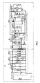
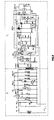
- the M motor of the fan presents a secondary winding at the ends of which the VBT low tension is collected, said low tension feeding the entire logical part L for the monitoring of the equipment which, as can be observed in Fig.2 is to be found after the terminals 1, 2.
- the feeding of the monitoring circuit entails the feeding of the A RF logic circuit and, through the latter the RPA1 relay is also fed.
- the feeding of said relay causes the 1RPA1 contact to close.
- the closing of the 1RPA1 contact makes it possible for the M motor to continue to be fed, even if in the meantime the PA contact has gone to its resting position from the feeding of the motor to the feeding of the RPA2 relay.
- the feeding of the monitoring circuit of the equipment also entails the energizing of the t1 timer, which starts counting down a period of time, for instance of about 20 ⁇ 70 seconds, this occurring as a function of the RC time constant of the t1 circuit due to the R, R1 resistances placed in series and to the inner capacity of the logic circuit of t1.
- the feeding of the t1 circuit closes through the 2RF contacts.
- the circuit of the equipment sends out a signal which opens the gas valves and also feeds a transformer connected with the spark.
- the ignition of the flame must occur within a maximum time span of 3 seconds from the end of the pre-ventilation.
- a first signal t1 1 is sent out by the logic circuit which excites the RT relay and, as a consequence, its RT1 and RT2 contacts close. These contacts permit a retention current through the BL2 resistance, also called second resistance, through the 2RPA2, RT1, RT2, RTA contacts
- the closing of the 2RTA contact with the 3RF contact in its resting position causes the REV relay to be fed through the BLS1 resistance, also called first resistance.
- the feeding of the REV relay entails the closing of the 1REV contact and, therefore, the consequent feeding of the REV1 relay placed in series with the RL relay. During this phase the RL relay is not excited.
- the corresponding EVS and EV1 solenoid valves for the gas distribution are opened, the EVS valve being the safety valve placed before the two EV1 and EV2 valves.
- the 1REV1 contact When the REV1 relay is excited, the 1REV1 contact also closes and, through the T3 contact and the 2RL contact, which is normally closed, it feeds the transformer feeding the TR spark. Therefore, all the conditions for the ignition of the flame are present, since the TR transformer feeding the spark and the EVS and EV1 solenoid valves for the gas distribution are being fed.
- the A RF flame sensor senses the ignition and all the contacts 1RF, 2RF, 3RF and 4RF, the last one being also called first contact, are commuted.
- the t1 timer stops being fed, so that the count down and any signal output are stopped.
- the RL relay is fed at full voltage, so that the normally closed 2RL contact opens and the igniting spark stops because of the interruption of the feeding of the TR transformer.
- the commutation of the 3RF contact causes the t2 timer to start counting, so that for the purpose of counting a signal is sent out such that it will excite the REV2 relay, as can be observed in Fig. 5.
- the EV2 solenoid valve also opens, since at the end of the count down by t2 the REV2 relay is excited and the 1REV2 contact feeds the EV2 solenoid valve. Therefore, during its normal operation, the burner is fed through the EVS safety valve and the EV1 and EV2 valves.
- the operation can be reset by the user by manually commuting the 1BL1 contact.
- the 1RTA and 2RTA contacts are also closed and, through the REV relay, feed said first BLS1 resistance, which is a resistance wound around a bi-metallic rod, which begins to heat up because of the movement of the bi-metal.
- this bi-metallic rod on which BLS1 is wound will commute the BLG1 contact.
- This commutation interrupts the feeding of the entire logic of the monitoring circuit and, as a consequence, also of the REV1 relay. This causes the opening of the REV1 contact which by opening stops the feeding of the EVS and EV1 solenoid valves.
- the traditional shutdown which occurs within the 3 seconds.
- This safety feature intervenes regardless of the operation of the electronic logic, since said safety feature depends on the electro-mechanic operation of a bi-metallic rod commuting the contacts after a very brief heating-up period.
- the BLG1 contact the commutation of which has caused the shutdown of the equipment, is protected so that it can not be accessible to the user, but only to specialized personnel, whose intervention becomes necessary, since the commutation of the BLG1 contact has only occurred because of a failure of the BL shutdown relay, so that it becomes important to replace it.
- the M motor for the pre-ventilation begins to be fed.
- the countdown of the logic circuit t1 should also start.
- the presence of a flame which is sensed by the A RF circuit for the monitoring of the flame the 1RF, 2RF, 3RF 4RF contacts are commuted.
- the RC charge circuit of the time constant of the timer t1 is not closed at this point, so that it is not possible for the first impulse t1 1 to be sent out, since the countdown is interrupted.
- the RPA1 relay Since the A RF flame monitoring contact is excited, the RPA1 relay is also excited and, as a consequence, the 2RPA2 contact, also called second contact, is commuted and it permits, also through the closing of said first 4RF contact, the feeding of said second BL shutdown relay through the second BL2 resistance, which is also wound around a bi-metallic element, deferring from the one previously described.
- the 2RPA2 contact also called second contact
- the T relay when the TL limit thermostat opens, the T relay is de-energized and, as a consequence, all the T1, T2, T3 and T4 contacts open.
- the opening of the T2 contact causes the solenoid valve of the REV2 relay to stop being energized.
- the corresponding EV2 solenoid valve is no longer energized. If no gas leaks out of the EVS safety solenoid valve, EV1 receives no gas, so that the flame goes out. If the flame goes out, the A RF relay commutes again and consequently the fourth E relay, which was kept in short circuit by the 2RF contact, is also excited.
- the corresponding 1E contact also opens and it causes the third B relay to open.
- the de-energizing of the third B relay causes also the opening of the contacts connected with said relay, i.e. the B1 and B2 contacts, which cause the M motor to stop: it then occurs that after the signal has been sent out by the limit thermostat, the motor keeps on working as long as the logic circuit which senses the presence of the flame insures that the flame is on.
- the system foresees that the motor, which supplies the combustion air, keeps supplying an amount of ventilation sufficient for the inlet gas to burn, thereby creating the ideal condition preventing dangerous situations due to the buid-up of unburnt gas.
Landscapes
- Engineering & Computer Science (AREA)
- Chemical & Material Sciences (AREA)
- Combustion & Propulsion (AREA)
- Mechanical Engineering (AREA)
- General Engineering & Computer Science (AREA)
- Control Of Combustion (AREA)
- Regulation And Control Of Combustion (AREA)
- Feeding And Controlling Fuel (AREA)
Priority Applications (1)
| Application Number | Priority Date | Filing Date | Title |
|---|---|---|---|
| EP97107692A EP0793059B1 (en) | 1992-10-07 | 1993-10-05 | Control and monitoring equipment for gas burners |
Applications Claiming Priority (2)
| Application Number | Priority Date | Filing Date | Title |
|---|---|---|---|
| ITVI920148A IT1259837B (it) | 1992-10-07 | 1992-10-07 | Apparecchiatura di controllo e comando per bruciatori a gas |
| ITVI920148 | 1992-10-07 |
Related Child Applications (1)
| Application Number | Title | Priority Date | Filing Date |
|---|---|---|---|
| EP97107692A Division EP0793059B1 (en) | 1992-10-07 | 1993-10-05 | Control and monitoring equipment for gas burners |
Publications (2)
| Publication Number | Publication Date |
|---|---|
| EP0591910A1 EP0591910A1 (en) | 1994-04-13 |
| EP0591910B1 true EP0591910B1 (en) | 1998-04-22 |
Family
ID=11425013
Family Applications (2)
| Application Number | Title | Priority Date | Filing Date |
|---|---|---|---|
| EP93116050A Expired - Lifetime EP0591910B1 (en) | 1992-10-07 | 1993-10-05 | Control and monitoring equipment for gas burners |
| EP97107692A Expired - Lifetime EP0793059B1 (en) | 1992-10-07 | 1993-10-05 | Control and monitoring equipment for gas burners |
Family Applications After (1)
| Application Number | Title | Priority Date | Filing Date |
|---|---|---|---|
| EP97107692A Expired - Lifetime EP0793059B1 (en) | 1992-10-07 | 1993-10-05 | Control and monitoring equipment for gas burners |
Country Status (4)
| Country | Link |
|---|---|
| EP (2) | EP0591910B1 (it) |
| AT (1) | ATE165434T1 (it) |
| DE (2) | DE69327811D1 (it) |
| IT (1) | IT1259837B (it) |
Family Cites Families (8)
| Publication number | Priority date | Publication date | Assignee | Title |
|---|---|---|---|---|
| US3488131A (en) * | 1964-10-26 | 1970-01-06 | Whirlpool Co | Electronic spark ignitor control for fuel burner |
| US3524717A (en) * | 1968-06-17 | 1970-08-18 | Electronics Corp America | Combustion supervision system |
| US3574495A (en) * | 1969-12-11 | 1971-04-13 | Honeywell Inc | Burner control system |
| CA1096464A (en) * | 1977-03-07 | 1981-02-24 | Russell B. Matthews | Fuel ignition system having interlock protection and electronic valve leak detection |
| US4243372A (en) * | 1979-02-05 | 1981-01-06 | Electronics Corporation Of America | Burner control system |
| US4482312A (en) * | 1979-06-20 | 1984-11-13 | Electronics Corporation Of America | Burner control system |
| DE3022635C2 (de) * | 1980-06-18 | 1984-11-22 | Danfoss A/S, Nordborg | Steuerschaltung für eine Feuerungsanlage |
| US4976459A (en) * | 1990-02-09 | 1990-12-11 | Inter-City Products Corporation (Usa) | Warmup method for a two stage furnace |
-
1992
- 1992-10-07 IT ITVI920148A patent/IT1259837B/it active IP Right Grant
-
1993
- 1993-10-05 EP EP93116050A patent/EP0591910B1/en not_active Expired - Lifetime
- 1993-10-05 EP EP97107692A patent/EP0793059B1/en not_active Expired - Lifetime
- 1993-10-05 DE DE69327811T patent/DE69327811D1/de not_active Expired - Lifetime
- 1993-10-05 AT AT93116050T patent/ATE165434T1/de not_active IP Right Cessation
- 1993-10-05 DE DE69318092T patent/DE69318092D1/de not_active Expired - Lifetime
Also Published As
| Publication number | Publication date |
|---|---|
| EP0793059A2 (en) | 1997-09-03 |
| EP0793059B1 (en) | 2000-02-02 |
| DE69318092D1 (de) | 1998-05-28 |
| ITVI920148A0 (it) | 1992-10-07 |
| DE69327811D1 (de) | 2000-03-09 |
| EP0591910A1 (en) | 1994-04-13 |
| ITVI920148A1 (it) | 1994-04-07 |
| ATE165434T1 (de) | 1998-05-15 |
| IT1259837B (it) | 1996-03-28 |
| EP0793059A3 (en) | 1997-10-01 |
Similar Documents
| Publication | Publication Date | Title |
|---|---|---|
| CA1166719A (en) | Self-checking safety switch control circuit | |
| JPH02242019A (ja) | 燃料バーナー制御システム及びその電気抵抗式点火器の付勢の制御方法 | |
| GB2036946A (en) | Fuel ignition and supply systems | |
| US3277949A (en) | Apparatus for hydrocarbon ignition and monitoring | |
| US4077762A (en) | Fuel ignition system having contact interlock protection | |
| US4106889A (en) | Burner ignition system | |
| US3484177A (en) | Igniter and control means | |
| US4194875A (en) | Intermittent pilot ignition system | |
| EP0591910B1 (en) | Control and monitoring equipment for gas burners | |
| US4850852A (en) | Gas valve shut off method and apparatus | |
| US4482312A (en) | Burner control system | |
| US4147496A (en) | Safety ignition means for burner installations | |
| US3059693A (en) | Control system | |
| US4025283A (en) | Electrical ignition systems for gas fired equipment | |
| US3432246A (en) | Electrical flame ignition and supervising apparatus | |
| US3443752A (en) | Control system for gas-fired heating apparatus | |
| KR930006171B1 (ko) | 연소제어장치 | |
| JPH08145355A (ja) | 燃焼制御装置 | |
| JPH08147051A (ja) | 電源制御装置 | |
| US4102630A (en) | Burner control system | |
| GB2109603A (en) | A cooking control and cooking apparatus including such a control | |
| US2185318A (en) | Control apparatus | |
| KR910005509B1 (ko) | 전자 무접점식 오일버어너용 연소안전 제어장치 | |
| US3259169A (en) | Burner safety control system | |
| JP3486065B2 (ja) | 燃焼装置 |
Legal Events
| Date | Code | Title | Description |
|---|---|---|---|
| PUAI | Public reference made under article 153(3) epc to a published international application that has entered the european phase |
Free format text: ORIGINAL CODE: 0009012 |
|
| AK | Designated contracting states |
Kind code of ref document: A1 Designated state(s): AT BE CH DE DK ES FR GB GR IT LI LU NL SE |
|
| 17P | Request for examination filed |
Effective date: 19941012 |
|
| 17Q | First examination report despatched |
Effective date: 19960124 |
|
| GRAG | Despatch of communication of intention to grant |
Free format text: ORIGINAL CODE: EPIDOS AGRA |
|
| GRAG | Despatch of communication of intention to grant |
Free format text: ORIGINAL CODE: EPIDOS AGRA |
|
| GRAH | Despatch of communication of intention to grant a patent |
Free format text: ORIGINAL CODE: EPIDOS IGRA |
|
| GRAH | Despatch of communication of intention to grant a patent |
Free format text: ORIGINAL CODE: EPIDOS IGRA |
|
| GRAA | (expected) grant |
Free format text: ORIGINAL CODE: 0009210 |
|
| AK | Designated contracting states |
Kind code of ref document: B1 Designated state(s): AT BE CH DE DK ES FR GB GR IT LI LU NL SE |
|
| DX | Miscellaneous (deleted) | ||
| PG25 | Lapsed in a contracting state [announced via postgrant information from national office to epo] |
Ref country code: NL Free format text: LAPSE BECAUSE OF FAILURE TO SUBMIT A TRANSLATION OF THE DESCRIPTION OR TO PAY THE FEE WITHIN THE PRESCRIBED TIME-LIMIT Effective date: 19980422 Ref country code: LI Free format text: LAPSE BECAUSE OF FAILURE TO SUBMIT A TRANSLATION OF THE DESCRIPTION OR TO PAY THE FEE WITHIN THE PRESCRIBED TIME-LIMIT Effective date: 19980422 Ref country code: IT Free format text: LAPSE BECAUSE OF FAILURE TO SUBMIT A TRANSLATION OF THE DESCRIPTION OR TO PAY THE FEE WITHIN THE PRESCRIBED TIME-LIMIT;WARNING: LAPSES OF ITALIAN PATENTS WITH EFFECTIVE DATE BEFORE 2007 MAY HAVE OCCURRED AT ANY TIME BEFORE 2007. THE CORRECT EFFECTIVE DATE MAY BE DIFFERENT FROM THE ONE RECORDED. Effective date: 19980422 Ref country code: GR Free format text: LAPSE BECAUSE OF FAILURE TO SUBMIT A TRANSLATION OF THE DESCRIPTION OR TO PAY THE FEE WITHIN THE PRESCRIBED TIME-LIMIT Effective date: 19980422 Ref country code: FR Free format text: LAPSE BECAUSE OF FAILURE TO SUBMIT A TRANSLATION OF THE DESCRIPTION OR TO PAY THE FEE WITHIN THE PRESCRIBED TIME-LIMIT Effective date: 19980422 Ref country code: ES Free format text: THE PATENT HAS BEEN ANNULLED BY A DECISION OF A NATIONAL AUTHORITY Effective date: 19980422 Ref country code: CH Free format text: LAPSE BECAUSE OF FAILURE TO SUBMIT A TRANSLATION OF THE DESCRIPTION OR TO PAY THE FEE WITHIN THE PRESCRIBED TIME-LIMIT Effective date: 19980422 Ref country code: BE Free format text: LAPSE BECAUSE OF FAILURE TO SUBMIT A TRANSLATION OF THE DESCRIPTION OR TO PAY THE FEE WITHIN THE PRESCRIBED TIME-LIMIT Effective date: 19980422 Ref country code: AT Free format text: LAPSE BECAUSE OF FAILURE TO SUBMIT A TRANSLATION OF THE DESCRIPTION OR TO PAY THE FEE WITHIN THE PRESCRIBED TIME-LIMIT Effective date: 19980422 |
|
| REF | Corresponds to: |
Ref document number: 165434 Country of ref document: AT Date of ref document: 19980515 Kind code of ref document: T |
|
| REG | Reference to a national code |
Ref country code: CH Ref legal event code: EP |
|
| REF | Corresponds to: |
Ref document number: 69318092 Country of ref document: DE Date of ref document: 19980528 |
|
| PG25 | Lapsed in a contracting state [announced via postgrant information from national office to epo] |
Ref country code: SE Free format text: LAPSE BECAUSE OF FAILURE TO SUBMIT A TRANSLATION OF THE DESCRIPTION OR TO PAY THE FEE WITHIN THE PRESCRIBED TIME-LIMIT Effective date: 19980722 Ref country code: DK Free format text: LAPSE BECAUSE OF FAILURE TO SUBMIT A TRANSLATION OF THE DESCRIPTION OR TO PAY THE FEE WITHIN THE PRESCRIBED TIME-LIMIT Effective date: 19980722 |
|
| PG25 | Lapsed in a contracting state [announced via postgrant information from national office to epo] |
Ref country code: DE Free format text: LAPSE BECAUSE OF FAILURE TO SUBMIT A TRANSLATION OF THE DESCRIPTION OR TO PAY THE FEE WITHIN THE PRESCRIBED TIME-LIMIT Effective date: 19980723 |
|
| EN | Fr: translation not filed | ||
| NLV1 | Nl: lapsed or annulled due to failure to fulfill the requirements of art. 29p and 29m of the patents act | ||
| PG25 | Lapsed in a contracting state [announced via postgrant information from national office to epo] |
Ref country code: LU Free format text: LAPSE BECAUSE OF NON-PAYMENT OF DUE FEES Effective date: 19981005 Ref country code: GB Free format text: LAPSE BECAUSE OF NON-PAYMENT OF DUE FEES Effective date: 19981005 |
|
| REG | Reference to a national code |
Ref country code: CH Ref legal event code: PL |
|
| PLBE | No opposition filed within time limit |
Free format text: ORIGINAL CODE: 0009261 |
|
| STAA | Information on the status of an ep patent application or granted ep patent |
Free format text: STATUS: NO OPPOSITION FILED WITHIN TIME LIMIT |
|
| 26N | No opposition filed | ||
| GBPC | Gb: european patent ceased through non-payment of renewal fee |
Effective date: 19981005 |