EP0591954B1 - Mit integralem Schlittenarm und Biegungsvorrichtung hergestellte Magnetkopfaufhängungseinheit - Google Patents
Mit integralem Schlittenarm und Biegungsvorrichtung hergestellte Magnetkopfaufhängungseinheit Download PDFInfo
- Publication number
- EP0591954B1 EP0591954B1 EP93116185A EP93116185A EP0591954B1 EP 0591954 B1 EP0591954 B1 EP 0591954B1 EP 93116185 A EP93116185 A EP 93116185A EP 93116185 A EP93116185 A EP 93116185A EP 0591954 B1 EP0591954 B1 EP 0591954B1
- Authority
- EP
- European Patent Office
- Prior art keywords
- assembly
- section
- load beam
- slider
- flexure
- Prior art date
- Legal status (The legal status is an assumption and is not a legal conclusion. Google has not performed a legal analysis and makes no representation as to the accuracy of the status listed.)
- Expired - Lifetime
Links
Images

Classifications
-
- G—PHYSICS
- G11—INFORMATION STORAGE
- G11B—INFORMATION STORAGE BASED ON RELATIVE MOVEMENT BETWEEN RECORD CARRIER AND TRANSDUCER
- G11B5/00—Recording by magnetisation or demagnetisation of a record carrier; Reproducing by magnetic means; Record carriers therefor
- G11B5/48—Disposition or mounting of heads or head supports relative to record carriers ; arrangements of heads, e.g. for scanning the record carrier to increase the relative speed
- G11B5/4806—Disposition or mounting of heads or head supports relative to record carriers ; arrangements of heads, e.g. for scanning the record carrier to increase the relative speed specially adapted for disk drive assemblies, e.g. assembly prior to operation, hard or flexible disk drives
- G11B5/4833—Structure of the arm assembly, e.g. load beams, flexures, parts of the arm adapted for controlling vertical force on the head
Definitions
- Copending U.S. patent application Serial Number 07/926,033 filed August 5, 1992 and corresponding European Application no EP93112484.5 are directed to a head suspension assembly particularly useful with nanosliders, which are about 50% of the size of the standard full size air bearing sliders.
- the present application discloses a modified and improved head suspension assembly especially useful with femtosliders, which are about 25% of the size of the standard full size sliders.
- This invention relates to a magnetic head suspension assembly that accommodates air bearing femtosliders which are used in compact disk drives.
- disk drives such as used in laptop or notebook computers, include at least one rotatable magnetic disk, at least one magnetic head assembly for transducing data recorded on the disk, and a rotary head actuator for transporting the magnetic head to selected data tracks on the rotating disk.
- the magnetic head assembly comprises a head suspension fabricated with a rigid load beam element and a gimbaling flexure.
- a typical head suspension includes a load beam element and a flexure which are fabricated as separate parts and are then joined during assembly of the head suspension.
- Such an assembly is known from US-A-5 081 553. Special tooling to implement accurate alignment and assembly of the load beam and flexure is required. After joinder of the load beam element and flexure, an air bearing slider is mounted at the end of the flexure. The slider supports a thin film magnetic transducer which coacts with the magnetic disk for recording or reading data signals.
- the rotating magnetic disk provides an aerodynamic lift force to the slider, while an opposing gram load force is applied to the slider through the flexure.
- the resultant of the two opposing forces determines the flying height of the slider and its transducer relative to the disk surface.
- the slider In its operating flying mode, the slider gimbals about a load dimple formed in the flexure.
- the load force transfer and gimbaling action are separate to provide high first bending frequency with low pitch and low stiffness.
- the flexure participates slightly in the load transfer with the load beam while primarily providing the low pitch and roll stiffness gimbaling action and providing high stiffness for lateral motion.
- These suspensions are characterized by weak pitch, roll and bending stiffness when the head is flying over the disk surface.
- the suspension structure should provide a high first bending mode resonant frequency so that the slider can follow variations in the topography of the rotating disk surface while providing low pitch and roll stiffness.
- a reduction in Z-height (vertical height) of the suspension and slider assembly results in a corresponding reduction in the Z-height of the compact disk drive incorporating the assembly.
- a standard full size slider is about 4.06x10 -3 M (0.160 inch) long, 3.18x10 -3 M (0.125 inch) wide and 8.76x10 -4 M (0.0345 inch) high.
- Presently known disk drives employ nanosliders that measure approximately 2.03x10 -3 M (0.080 inch) long, 1.6x10 -3 M (0.063 inch) wide and 4.32x10 -4 M (0.017 inch) high, which size is about 50% of the size of a standard slider.
- novel suspension and slider design disclosed herein is particulary useful for femtosliders, which measure about 1.02 x 10 -3 M (0.040 inch) long, 5.08x10 -4 M to 6.6x10 -4 M (0.020-0.026 inch) wide and 2.5x10 -4 M (0.0110 inch) in overall height, which size is about 25% of the size of a standard full size slider. It should be understood that the novel design may be used with other size sliders as well.
- An object of this invention is to provide a head suspension and slider assembly having significantly reduced Z-height.
- Another object of this invention is to provide a head suspension assembly characterized by low pitch and roll stiffness.
- Another object is to provide a head suspension assembly characterized by low bending stiffness with decreased gram load tolerance effects.
- Another object is to provide a head suspension assembly characterized by a relatively high first bending mode, first torsion mode, and first lateral mode resonant frequencies.
- a further object is to provide a head suspension design that affords significant savings and advantages in manufacture and mass production.
- a magnetic head suspension assembly is formed from an integral planar piece comprising a load beam section and flexure section, as laid down in claim 1.
- the load beam is configured preferably as a truncated conical section having flanges along its sides and an extending tongue at its narrow end.
- the side flanges are formed with U-shaped channels and provide rigidity and stiffness to the load beam section.
- the load beam tongue extends into the flexure section and is formed with a hemispherical load dimple which faces down to the non-air bearing surface of a head slider.
- a U-shaped cutout portion that is formed in the flexure section adjacent to the load beam tongue delineates the shape of the tongue.
- the flexure section includes two narrow etched legs that extend from the load beam and are disposed adjacent to the cutout portion. The narrow legs are connected by a lateral ear at the end of the flexure.
- the head slider is bonded to the bottom surface of the lateral ear.
- the flexure section includes outriggers configured as a split tongue to which the slider is bonded.
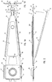
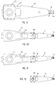
- a magnetic head suspension assembly includes a load beam section 10, a flexure section 12, a leaf spring section 56 and a rear mount section 42.
- the suspension is formed from an integral flat piece of nonmagnetic material, preferably a 300 Series type stainless steel having a thickness of about 3.05x10 -5 to 3.81x10 -5 M (0.0012 to 0.0015 inch).
- the load beam section 10 and flexure section 12, as well as the leaf spring section 56 and rear mount section 42 are disposed substantially in a single plane. No separate forming of individual load beam and flexure parts is required. Therefore, no assembly steps of joining and welding are needed for attaching the flexure to the load beam.
- the load beam section 10 is preferably made in a truncated conical or triangular shape.
- the load beam section has a short tapered tongue 14 extending from its relatively narrow end into the flexure section 12.
- the tongue 14 is delineated by a U-shaped cutout 16 in the flexure section.
- the load beam tongue 14 provides low deflections in the direction orthogonal to the plane of the load beam section and flexure section by virtue of its short length and low gram load force.
- a constrained layer damping element 19 made of elastomer 10A about 5.08x10 -5 M (0.002 inch) thick and an overlay 10B of about 5.08x10 -5 M (0.002 inch) thick stainless steel is laid down on the top surface of the major section of the load beam to minimize undesirable resonances of the suspension, as shown in Fig. 1.
- a similar damping element 21 may be deposited on the bottom surface of the load beam without interfering with the flexure 12, as shown in Fig. 3.
- the flexure section 12 includes narrow legs 32 that are located adjacent to the sides of the U-shaped cutout 16.
- the flexure legs 32 are chemically etched to a thickness of about 2.54x10 -5 M (0.0010 inch) for increased flexibility.
- the narrow legs 32 are thin and relatively weak to allow the desired gimbaling action about the load dimple 18 and also to allow the suspension to have low roll and pitch stiffness.
- a lateral connecting part or ear 38 is formed with the integral flat load beam and flexure to connect ends of the narrow legs 32.
- a slider 22 is bonded to the lateral connecting part 38.
- a hemispherical load dimple 18 is formed on the load beam tongue 14 and is in contact with the top non-air bearing surface of an air bearing slider 22 that is bonded to the lateral part or ear 38.
- the load dimple 18 is formed so that the hemisphere of the dimple faces down to the slider.
- the dimple 18 may be offset, 0-0.006 inch for example, from the centerline of the slider in order to control flying height characteristics.
- U-shaped flanges 24 extend along the sides of the load beam section and are truncated before reaching the flexure section 12.
- the flanges 24 contribute to the stiffness of the load beam section and localizes the bending action to the spring section 56, thereby minimizing the pitch attitude changes due to arm/disk vertical tolerances.
- Head circuitry wiring 92 without the conventional tubing is located within the channels of the flanges 24. The absence of tubing allows the U-shaped channels of the flanges 24 to be relatively shallow thereby contributing to the reduction of the Z-height of the head suspension assembly.
- Adhesive material 90 is used to maintain the wiring 92 fixed in place.
- Adhesive fillets 91 are provided adjacent to the ear 38 and the slider 22. The fillets 91 are exposed and thus can be cured easily by application of ultraviolet radiation.
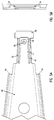
- a feature of the head suspension and slider assembly disclosed herein is that the slider 22 is configured with a step 28, which is formed by cutting a recessed portion or platform 30 on the non-air bearing top surface of the slider 22.
- the Z-height of the step 28 is substantially the same as the Z-height of the hemispherical load dimple 18.
- Sufficient spacing is provided between the load beam tongue 14 and the top slider surface to allow free gimbaling action of the slider 22 with no interference from the load beam.
- the slider step 28 is sufficiently high so that the slider end at the trailing edge can accommodate a thin film magnetic transducer including its coil turns.
- the leaf spring 56 between the load beam section 10 and the rear mount section 42 is formed with a trapezoidal-like cutout 60 to provide flexibility.
- the flexible section 56 is formed to provide a desired load force that counteracts the aerodynamic lift force generated by the rotating disk during operation of the disk drive.
- the load force arises from bending the suspension from the phantom position, shown in Fig. 2, to the raised position as indicated by the arrow.
- the rear mount section 42 of the load beam 10 has a hole 48 to allow connection of a swage plate 46 to the suspension by means of a boss 48 and by laser welding.
- the swage plate 46 provides stiffness to the rear mount section 42.
- Rear flanges 54 provide wire routing channels to protect the wires during handling.
- the head suspension and slider assembly described herein incorporates a stiff load beam and a relatively long and narrow flexure which includes thin weak flexure legs and connecting lateral part. With this design, low bending stiffness and high lateral and longitudinal stiffness with low roll and pitch stiffness are realized.
- the load beam tongue has a high vertical or perpendicular stiffness so that there is minimal bending of the load beam tongue up or down relative to the plane of the suspension.
- the first bending mode resonant frequency or vibration is substantially higher than known prior art suspension designs of comparable size.
- the overall height of the slider is about 2.54x10 -4 M (0.0110 inch), its length about 1.02x10 -3 M (0.0400 inch), and its width about 5.08x10 -4 M (0.020 inch).
- the height of the step 28 is about 3.81x10 -5 M (0.0015 inch) above the recessed portion 30 which is 8.53x10 -4 M (0.0336 inch) long.
- the surface area of the top of the step 28 is preferably minimized in size to reduce the effects of bending or warping at the surface of the slider step which may occur due to the difference in the thermal coefficients of expansion of the ceramic slider 22 and the stainless steel ear 38. Such bending would affect the flying characteristics of the head adversely.
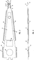
- the flexure section 62 is formed with a tongue 64 and a cutout 66.
- a down-facing load dimple 76 is provided on the tongue 64.
- Narrow etched legs 68 that extend from the load beam 10 are connected by a transverse part 70.
- the legs 68 are chemically etched to be thinner than the integral flat piece used to form the load beam and flexure sections.
- Outriggers 72 forming a split tongue are provided at the sides of the flexure 62 and are separated from the thin legs 68 by cutouts 74. The outriggers 72 overhang the sides of the slider 22 and the slider is fastened to the outriggers by an adhesive fillet 90.
- the top non-air bearing surface 20 of the slider 22 is bonded to the outriggers 72 by adhesive fillets which provide bond strength at the cutout 16, as shown in Fig. 6C.
- the slider 22 is mounted to the outriggers 72 so that the center of the slider is aligned with the load dimple 76, and the slider projects beyond the end of the transverse part 70. There is no offset of the load dimple 76 relative to the centerline of the slider. With this implementation, a lower vertical height (Z-height) is realized. Also the slider bonding areas of the outriggers 72 are larger than the bonding area of the lateral connecting part 38 of flexure 12 of Fig. 1.
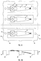
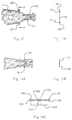
- Fig. 8 shows a paddleboard or fret 80 formed from a stainless steel piece that has been stamped with a number of head suspensions 82, each of which was formed with the design shown in Fig. 1. Tooling holes 84 and support legs 86 are provided for further handling.
- Fig. 8A shows the paddleboard 80 with support legs 86 bent to enable working on the extremely small femtoslider suspensions.
- Fig. 9 shows a nanoslider suspension such as disclosed in copending application Serial Number 07/926,033.
- the nanoslider includes a load beam 94, flexure 96, load beam tongue 98, spring section 100, rear mount section 102 and slider 104.
- Figs.10 and 11 illustrate the femtoslider suspension of this invention with the load beam 10, flexure 12, spring section 56 and a rear section having a tooling hole 106.
- the tooling hole section 106 is attached to an extension 108 formed with an apertured swage 110 that allows attachment to a rotary actuator.
- the extension 108 serves as an arm pivot and precludes the need for a separate arm structure, as used in the prior art.
- the extension 108 also allows the assembly to match the overall length of other industry standard "70%" microslider suspensions, thereby making it easy to use existing tooling.
- Fig. 11 shows the suspension skewed with relation to the extension 108 to compensate for skew experienced as the head moves between the outer diameter and the inner diameter of the disk during accessing.
- the extension may include apertures 112 for weight reduction, as shown in Figs. 10 and 11.
- the apertures 112 serve to adjust for resonant conditions and/or to adjust for total actuator balance about the pivot.
- Fig. 12 illustrates the femtoslider suspension without the extension and shows the large difference in size between the nanoslider and femtoslider suspensions.
- the length was about 0.01M (0.395 inch) and the greatest width was about 1.42x10 -3 M (0.056 inch).
- a head slider suspension includes flat side tabs 120 which protrude to enable loading and unloading of the head suspension assembly relative to the surface of a magnetic disk in a disk drive.
- the side tabs may be present on one or both sides of the load beam.
- the side tabs 120 are moved by means of a tool for lifting or lowering the suspension assembly.
- the addition of the flat side tabs which are in the same plane as the load beam does not add to the vertical Z-height of the suspension assembly.
- Figs. 14A-C depict a partial suspension assembly having a slider 122 and a thin film transducer 124 at a slider end.
- the slider 122 has a flat top surface 126 on which the load dimple 76 is seated.
- the slider 122 is not formed with a step 78, as shown in the slider design of Fig. 7.
- the flat surface 126 extends across the entire top of the slider.
- the front end of the flexure 128 is bent at sections 130 and 132, as shown in Fig. 14B to allow the flexure to come down by distance substantially equivalent to the height of the load dimple 76. In this way, the flexure 128 contacts the flat top surface 126 of the slider 122.
- the slider is bonded to the bent sections 130 and 132 by adhesive fillets 134 and 136.
- the flat contact surfaces of flexure 128 and flat surface 126 at the top of the slider are also bonded together by adhesive.
- a single integral piece is formed with a load beam and flexure, thereby realizing a significant savings in material and labor. Alignment of the load beam and flexure and welding of the separate parts are eliminated. Certain critical tolerances that were required in former load beam/flexure assemblies are no longer needed thereby enhancing the assembly process.
- the design allows the separation of the load transfer function from the gimbaling action which eliminates the weak bending characteristic found with prior art suspensions. It should be understood that the parameters, dimensions and materials, among other things, may be modified within the scope of the invention. For example, the slider design with the step and platform configuration disclosed herein can be used with a "50%" nanoslider suspension or other size suspensions.
Landscapes
- Supporting Of Heads In Record-Carrier Devices (AREA)
Claims (22)
- Magnetkopfaufhängungseinheit zur Übertragung von Daten, die auf einer Fläche einer drehenden Magnetplatte aufgezeichnet sind und daraus gelesen werden, wobei der Antrieb aufweist:
einen Schlittenarmabschnitt (10) und einen Biegeteilabschnitt (12), um einen Kopfschieber zu befestigen,
gekennzeichnet durchein einstückiges Stück einer bestimmten Dicke, welches den Schlittenarmabschnitt (10) und den Biegeteilabschnitt (12) umfaßt, wobei der Schlittenarmabschnitt (10) Seiten und eine Zunge (14) an einem Ende hat, die sich in den Biegeteilabschnitt (12) erstrecken;einen Ausschnitt (16) im Biegeteilabschnitt (12), der die Schlittenarmzunge (14) begrenzt;schmale Schenkel (32), die wesentlich dünner als das Stück mit der bestimmten Dicke sind, die längs der Seiten des Ausschnittes (16) und benachbart und beabstandet von der Zunge (14) sind;wobei die Ladekraft im wesentlichen über die Zunge (14) übertragen wird und unabhängig von der Kardanwirkung und der seitlichen Positionierung ist, die durch die schmalen Schenkel (32) bereitgestellt wird. - Einheit nach Anspruch 1, die einen Kopfschieber (22) umfaßt, der eine obere Nicht-Luftlagerfläche hat, die am Biegeabschnitt (12) befestigt ist.
- Einheit nach Anspruch 2, die eine Einrichtung umfaßt, die mit dem Biegeteilabschnitt (12) ausgebildet ist, um den befestigten Kopfschieber (22) zu lagern.
- Einrichtung nach Anspruch 3, wobei die Lagereinrichtung Ausleger (72) oder eine Spreizzunge umfaßt, die an den äußeren Rändern des Biegeteilabschnitts (12) gebildet sind.
- Einheit nach Anspruch 3, wobei die Lagereinrichtung ein seitliches Teil (38) umfaßt, welches die schmalen Schenkel (32) verbindet.
- Einheit nach Anspruch 2, wobei der Schieber (22) ungefähr 2,79 x 10⁻⁴m (0,0110 Inch) hoch ist, 1,02 x 10⁻³m (0,0400 Inch) lang ist und 5,08 x 10⁻⁴m bis 6,60 x 10⁻⁴m (0,0200 bis 0,0260 Inch) breit ist.
- Einheit nach Anspruch 2, wobei der Schieber (22) eine Stufe (28) aufweist, die einer Plattform (30) benachbart ist.
- Einheit nach Anspruch 7, wobei die Plattform (30) des Schiebers (22) ungefähr 8,53 x 10⁻⁴m (0,0336 Inch) lang ist, und die Stufe ungefähr 3,81 x 10⁻³m (0,0015 Inch) hoch ist.
- Einheit nach Anspruch 2, die eine Ladevertiefung (18) besitzt, welche in der Zunge (14) gebildet ist.
- Einheit nach Anspruch 9, wobei die Ladevertiefung (18) eine Halbkugelform besitzt und nach unten in Kontakt mit der Kopffläche des Schiebers (22) gewandt ist.
- Einheit nach Anspruch 1, wobei das einstückige Stück, welches die Spreizzunge und das seitliche Teil (38) besitzt, ungefähr 3,05 x 10⁻⁵ bis 3,81 x 10⁻⁵m (0,0012 bis 0,0015 Inch) dick ist und die schmalen Schenkel (32) ungefähr 2,54 x 10⁻⁵m (0,0010 Inch) dick sind.
- Einheit nach Anspruch 1, wobei der Schlittenarmabschnitt (10) als stumpfes Dreieck ausgebildet ist.
- Einheit nach Anspruch 1, die einen Befestigungsabschnitt (42) am hinteren Ende des Schlittenarmabschnitts (10) besitzt, um das Befestigen der Aufhängung an einem Betätigungsarm zu ermöglichen; und einen Blattfederabschnitt (56) zwischen dem hinteren Befestigungsabschnitt (42) und dem Schlittenarmabschnitt (10), um Flexibilität für die Aufhängung bereitzustellen.
- Einheit nach Anspruch 13, die eine Stanzplatte (46) umfaßt, die mit dem Befestigungsabschnitt (42) verbunden ist, um Formfestigkeit für das hintere Ende der Aufhängungseinheit bereitzustellen.
- Einheit nach Anspruch 13, die vordere Flansche (24) aufweist, die längs der Ränder des Schlittenarmabschnitts (10) gebildet sind, und hintere Flansche (54), die längs der Ränder des hinteren Befestigungsabschnitts (42) gebildet sind, mit einer Lücke zwischen den vorderen und hinteren Flanschen.
- Einheit nach Anspruch 15, wobei die vorderen Flansche (24) als flache U-förmige Kanäle ausgebildet sind, und die elektrische Verdrahtung (92) ohne Verrohrung innerhalb der Kanäle angeordnet ist.
- Einheit nach Anspruch 1, die einen Ausschnitt (60) im Blattfederabschnitt (56) besitzt, um Flexibilität für die Aufhängung bereitzustellen.
- Einheit nach Anspruch 1, die außerdem eine geöffnete Erweiterung (108) besitzt, die mit der Aufhängungseinheit gebildet ist, um die Befestigung eines Betätigungsglieds eines Plattenantriebs ohne einen separaten Kopfarm zu ermöglichen, um das Verdrehen der Aufhängungseinheit zu ermöglichen.
- Einheit nach Anspruch 1, die ein Dämpfungsmaterial (19) aufweist, welches auf dem Schlittenarm (10) aufgebracht ist.
- Einheit nach Anspruch 1, die einen Lade/Entladeansatz (120) besitzt, der an zumindest einer der Seiten des Schlittenarmabschnitts (10) gebildet ist.
- Einheit nach Anspruch 2, wobei die obere Nicht-Luftlagerfläche in etwa flach ist.
- Einheit nach Anspruch 21, wobei der Biegeteilabschnitt (12) gebogene Abschnitte (130, 132) aufweist, um einen Kontakt des Biegeteilabschnitts (12) mit der oberen Fläche des Schiebers (22) zu ermöglichen.
Applications Claiming Priority (4)
| Application Number | Priority Date | Filing Date | Title |
|---|---|---|---|
| US42906 | 1987-04-27 | ||
| US95851692A | 1992-10-07 | 1992-10-07 | |
| US958516 | 1992-10-07 | ||
| US08/042,906 US5282103A (en) | 1992-10-07 | 1993-04-05 | Magnetic head suspension assembly fabricated with integral load beam and flexure |
Publications (3)
| Publication Number | Publication Date |
|---|---|
| EP0591954A2 EP0591954A2 (de) | 1994-04-13 |
| EP0591954A3 EP0591954A3 (en) | 1995-11-08 |
| EP0591954B1 true EP0591954B1 (de) | 1998-01-07 |
Family
ID=26719766
Family Applications (1)
| Application Number | Title | Priority Date | Filing Date |
|---|---|---|---|
| EP93116185A Expired - Lifetime EP0591954B1 (de) | 1992-10-07 | 1993-10-06 | Mit integralem Schlittenarm und Biegungsvorrichtung hergestellte Magnetkopfaufhängungseinheit |
Country Status (5)
| Country | Link |
|---|---|
| US (4) | US5282103A (de) |
| EP (1) | EP0591954B1 (de) |
| JP (1) | JPH06215511A (de) |
| CN (1) | CN1085679A (de) |
| DE (1) | DE69316131T2 (de) |
Cited By (18)
| Publication number | Priority date | Publication date | Assignee | Title |
|---|---|---|---|---|
| US8675314B1 (en) | 2013-08-21 | 2014-03-18 | Hutchinson Technology Incorporated | Co-located gimbal-based dual stage actuation disk drive suspensions with offset motors |
| US8681456B1 (en) | 2012-09-14 | 2014-03-25 | Hutchinson Technology Incorporated | Co-located gimbal-based dual stage actuation disk drive suspensions |
| US8717712B1 (en) | 2013-07-15 | 2014-05-06 | Hutchinson Technology Incorporated | Disk drive suspension assembly having a partially flangeless load point dimple |
| US8792214B1 (en) | 2013-07-23 | 2014-07-29 | Hutchinson Technology Incorporated | Electrical contacts to motors in dual stage actuated suspensions |
| US8861141B2 (en) | 2012-08-31 | 2014-10-14 | Hutchinson Technology Incorporated | Damped dual stage actuation disk drive suspensions |
| US8891206B2 (en) | 2012-12-17 | 2014-11-18 | Hutchinson Technology Incorporated | Co-located gimbal-based dual stage actuation disk drive suspensions with motor stiffener |
| US8896969B1 (en) | 2013-05-23 | 2014-11-25 | Hutchinson Technology Incorporated | Two-motor co-located gimbal-based dual stage actuation disk drive suspensions with motor stiffeners |
| US8896968B2 (en) | 2012-10-10 | 2014-11-25 | Hutchinson Technology Incorporated | Co-located gimbal-based dual stage actuation disk drive suspensions with dampers |
| US8896970B1 (en) | 2013-12-31 | 2014-11-25 | Hutchinson Technology Incorporated | Balanced co-located gimbal-based dual stage actuation disk drive suspensions |
| US8941951B2 (en) | 2012-11-28 | 2015-01-27 | Hutchinson Technology Incorporated | Head suspension flexure with integrated strain sensor and sputtered traces |
| US9001469B2 (en) | 2012-03-16 | 2015-04-07 | Hutchinson Technology Incorporated | Mid-loadbeam dual stage actuated (DSA) disk drive head suspension |
| US9245555B2 (en) | 2010-05-24 | 2016-01-26 | Hutchinson Technology Incorporated | Low resistance ground joints for dual stage actuation disk drive suspensions |
| US9431042B2 (en) | 2014-01-03 | 2016-08-30 | Hutchinson Technology Incorporated | Balanced multi-trace transmission in a hard disk drive flexure |
| US9558771B2 (en) | 2014-12-16 | 2017-01-31 | Hutchinson Technology Incorporated | Piezoelectric disk drive suspension motors having plated stiffeners |
| US9564154B2 (en) | 2014-12-22 | 2017-02-07 | Hutchinson Technology Incorporated | Multilayer disk drive motors having out-of-plane bending |
| US9646638B1 (en) | 2016-05-12 | 2017-05-09 | Hutchinson Technology Incorporated | Co-located gimbal-based DSA disk drive suspension with traces routed around slider pad |
| US9734852B2 (en) | 2015-06-30 | 2017-08-15 | Hutchinson Technology Incorporated | Disk drive head suspension structures having improved gold-dielectric joint reliability |
| US9824704B2 (en) | 2015-02-17 | 2017-11-21 | Hutchinson Technology Incorporated | Partial curing of a microactuator mounting adhesive in a disk drive suspension |
Families Citing this family (128)
| Publication number | Priority date | Publication date | Assignee | Title |
|---|---|---|---|---|
| US6600631B1 (en) * | 1989-11-27 | 2003-07-29 | Censtor Corp. | Transducer/flexure/conductor structure for electromagnetic read/write system |
| JP2767666B2 (ja) * | 1992-06-01 | 1998-06-18 | 富士通株式会社 | 磁気ヘッド用スプリングアーム |
| US5282103A (en) * | 1992-10-07 | 1994-01-25 | Read-Rite Corporation | Magnetic head suspension assembly fabricated with integral load beam and flexure |
| US5434731A (en) * | 1992-11-12 | 1995-07-18 | Seagate Technology, Inc. | Process for making a one-piece flexure for small magnetic heads |
| US6154344A (en) * | 1993-03-24 | 2000-11-28 | Hutchinson Technology Incorporated | Bonded wire capture |
| US5612841A (en) * | 1993-06-15 | 1997-03-18 | Seagate Technology, Inc. | Flexure assembly for hard disc drive heads |
| JP2739927B2 (ja) * | 1993-08-19 | 1998-04-15 | インターナショナル・ビジネス・マシーンズ・コーポレイション | ロード・ビーム |
| USH1425H (en) * | 1993-09-22 | 1995-04-04 | Wolter; Raymond R. | Head suspension assembly having improved frequency response, accurate head positioning and minimized flying variation |
| US5450747A (en) * | 1993-12-27 | 1995-09-19 | International Business Machines Corporation | Method for optimizing piezoelectric surface asperity detection sensor |
| US5423207A (en) * | 1993-12-27 | 1995-06-13 | International Business Machines Corporation | Advanced PZT glide head design and implementation for a small slider |
| JP3262445B2 (ja) * | 1994-02-18 | 2002-03-04 | 富士通株式会社 | ヘッドアセンブリ及び記憶装置 |
| JP2955829B2 (ja) * | 1994-04-15 | 1999-10-04 | ハッチンソン テクノロジー インコーポレイテッド | ヘッドサスペンション |
| US5608590A (en) * | 1994-06-20 | 1997-03-04 | Hutchinson Technology Incorporated | Gimballing flexure with static compensation and load print intregal etched features |
| WO1996001470A1 (en) * | 1994-07-06 | 1996-01-18 | Intégral Peripherals, Inc. | Improved air bearing slider and head gimbal assembly |
| US5473488A (en) * | 1994-08-03 | 1995-12-05 | Hutchinson Technology Incorporated | Static attitude adjustment via a solidified drop for a magnetic head suspension |
| JP3329953B2 (ja) * | 1994-09-16 | 2002-09-30 | インターナショナル・ビジネス・マシーンズ・コーポレーション | ヘッドアクチュエータ |
| WO1996010820A1 (en) * | 1994-09-30 | 1996-04-11 | Quantum Corporation | Head-gimbal assembly with reduced static attitude bias |
| US5539596A (en) * | 1994-12-29 | 1996-07-23 | International Business Machines Corporation | Integrated suspension, actuator arm and coil assembly with common structural support layer |
| US5585979A (en) * | 1995-03-28 | 1996-12-17 | International Business Machines Corporation | Assembly and method for wire encapsulation within head gimbal assemblies of DASD files |
| KR19990008454A (ko) * | 1995-05-08 | 1999-01-25 | 앤드류크라이더 | 경량 판독/기록 헤드를 지지하는 현가 장치 설계 |
| US5666241A (en) * | 1995-07-10 | 1997-09-09 | Magnecomp Corp. | Double dimple disk drive suspension |
| US5636089A (en) * | 1995-08-01 | 1997-06-03 | Hutchinson Technology Incorporated | Head suspension with spaced static attitude compensation protuberance and load dimple |
| JP3400248B2 (ja) * | 1995-08-30 | 2003-04-28 | インターナショナル・ビジネス・マシーンズ・コーポレーション | ディスク・ドライブ装置用のヘッド・サスペンションのロード・ビーム |
| US6031688A (en) * | 1995-09-19 | 2000-02-29 | Magnecomp Corp. | Suspension mounting plate with cantilevered load beam support |
| US5815349A (en) * | 1995-09-21 | 1998-09-29 | International Business Machines Corporation | Suspension with wire protection which does not impact slider movements |
| US5677815A (en) * | 1995-10-27 | 1997-10-14 | Chan; Hon Po | Support arm for use in an actuator assembly of a digital storage system with the support arm being formed from a polymer and including a grounding conductor |
| US6215622B1 (en) | 1996-01-02 | 2001-04-10 | International Business Machines Corporation | Laminated hard disk head suspension and etching process |
| US5742996A (en) * | 1996-01-03 | 1998-04-28 | International Business Machines Corporation | Method of manufacturing a transducer suspension system |
| US5617274A (en) * | 1996-01-12 | 1997-04-01 | International Business Machines Corporation | Low profile integral flexure for closely packed disks in a disk drive assembly |
| US5930079A (en) * | 1996-08-21 | 1999-07-27 | Magnecomp Corp. | Suspension having limited travel flexure for improved loadability |
| US5956209A (en) * | 1996-10-04 | 1999-09-21 | International Business Machines Corporation | Integrated suspension flexure having a compliant tip termination platform |
| US5742454A (en) * | 1996-10-09 | 1998-04-21 | Magnecomp Corp. | Unitary load beam and cam follower |
| US6147839A (en) * | 1996-12-23 | 2000-11-14 | Hutchinson Technology, Inc. | Head suspension with outriggers extending across a spring region |
| US5959806A (en) * | 1997-06-12 | 1999-09-28 | Read-Rite Corporation | Adaptive loading/unloading suspension |
| KR100307605B1 (ko) * | 1997-08-26 | 2001-10-19 | 가나이 쓰도무 | 자기헤드지지기구 |
| US5956212A (en) * | 1997-12-29 | 1999-09-21 | Headway Technologies, Inc. | Static attitude adjustment of a trace-suspension assembly |
| US6573711B1 (en) * | 1998-01-08 | 2003-06-03 | Seagate Technology Llc | Paddle board with extended flexible leads |
| JP3257500B2 (ja) * | 1998-02-27 | 2002-02-18 | ティーディーケイ株式会社 | 磁気ヘッド装置 |
| US6462911B1 (en) * | 1998-08-28 | 2002-10-08 | Hitachi, Ltd. | Magnetic head support mechanism and magnetic disk device |
| WO2000030081A1 (en) * | 1998-11-13 | 2000-05-25 | Tdk Corporation | Record/reproduce head support mechanism and record/reproduce apparatus |
| US6246547B1 (en) * | 1999-02-16 | 2001-06-12 | Read-Rite Corporation | Low profile flexure and slider-flexure assembly |
| JP2000268513A (ja) * | 1999-03-17 | 2000-09-29 | Tdk Corp | ヘッドスライダ支持体、ヘッド装置およびそれらの製造方法、ならびに情報記録再生装置 |
| JP4017303B2 (ja) * | 1999-09-30 | 2007-12-05 | 日東電工株式会社 | 磁気ヘッドサスペンションの製造方法および磁気ヘッドサスペンション用の金属基板の検査方法 |
| US6614627B1 (en) * | 2000-02-14 | 2003-09-02 | Hitachi, Ltd. | Magnetic disk apparatus |
| JP4101492B2 (ja) * | 2000-10-23 | 2008-06-18 | 松下電器産業株式会社 | ヘッド支持機構 |
| JP2002269713A (ja) * | 2001-03-12 | 2002-09-20 | Tdk Corp | ヘッド支持体の加工方法 |
| CN1292404C (zh) | 2001-05-03 | 2006-12-27 | 西加特技术有限责任公司 | 叠层悬架的辅助机构和微致动器具 |
| CN1288629C (zh) * | 2001-05-23 | 2006-12-06 | 西加特技术有限责任公司 | 具有一复合材料层的存储装置用的加强悬架 |
| JP4329920B2 (ja) * | 2001-06-04 | 2009-09-09 | 日本発條株式会社 | ディスクドライブ用サスペンションとその製造方法 |
| JP4269132B2 (ja) * | 2001-06-27 | 2009-05-27 | 日本発條株式会社 | ディスクドライブ用サスペンション |
| US7283330B2 (en) * | 2002-04-25 | 2007-10-16 | Hitachi Global Storage Technologies Netherlands B.V. | Method of manufacturing a suspension using coining |
| EP1527443A1 (de) * | 2002-08-06 | 2005-05-04 | Matsushita Electric Industrial Co., Ltd. | Kopfhalterungseinrichtung und plattenvorrichtung damit |
| JP4112379B2 (ja) * | 2003-01-14 | 2008-07-02 | サンコール株式会社 | 磁気ヘッドサスペンション |
| WO2004066302A1 (ja) * | 2003-01-21 | 2004-08-05 | Fujitsu Limited | ヘッド支持機構 |
| CN100517467C (zh) | 2003-05-12 | 2009-07-22 | 新科实业有限公司 | 用于形成微致动器的方法和系统 |
| US7099118B2 (en) * | 2003-06-02 | 2006-08-29 | Seagate Technology Llc | One-piece suspension assembly including interconnect |
| WO2005029494A1 (en) * | 2003-09-25 | 2005-03-31 | Sae Magnetics (H.K.) Ltd. | Treatment system and method for a head gimbal assembly static altitude control |
| JP3828532B2 (ja) | 2003-10-29 | 2006-10-04 | Tdk株式会社 | 検査装置および検査方法 |
| JP3878935B2 (ja) | 2003-10-29 | 2007-02-07 | Tdk株式会社 | 磁気ヘッドにおけるスライダ搭載位置測定方法、測定装置及び当該装置を用いた磁気ヘッドの製造装置 |
| JP4074265B2 (ja) * | 2004-04-28 | 2008-04-09 | 株式会社東芝 | ヘッドサスペンションアッセンブリおよびこれを備えたディスク装置 |
| US7724476B1 (en) * | 2004-09-16 | 2010-05-25 | Hutchinson Technology Incorporated | Coined headlift with formed rail offset for a disk drive head suspension component |
| US7352534B2 (en) * | 2005-02-11 | 2008-04-01 | Hitachi Global Storage Technologies Netherlands, B.V. | Flexure leg optimization shapes for lateral stiffness |
| JP4727264B2 (ja) * | 2005-03-17 | 2011-07-20 | 日本発條株式会社 | ヘッド・サスペンション |
| JP4382696B2 (ja) | 2005-05-09 | 2009-12-16 | 日本発條株式会社 | ヘッド・サスペンションの製造方法 |
| JP4390148B2 (ja) * | 2005-05-09 | 2009-12-24 | 日本発條株式会社 | ヘッド・サスペンションの製造方法 |
| JP4382695B2 (ja) * | 2005-05-09 | 2009-12-16 | 日本発條株式会社 | ヘッド・サスペンション |
| US8756776B1 (en) | 2005-12-09 | 2014-06-24 | Western Digital Technologies, Inc. | Method for manufacturing a disk drive microactuator that includes a piezoelectric element and a peripheral encapsulation layer |
| US7433156B2 (en) * | 2006-02-10 | 2008-10-07 | Sae Magnetics (Hk) Ltd. | Flexure for minimizing fly height modulation of near-contact recording sliders in a disk drive |
| US7646565B2 (en) | 2006-08-08 | 2010-01-12 | International Business Machines Corporation | Tape head with outrigger |
| JP2008059663A (ja) * | 2006-08-30 | 2008-03-13 | Fujitsu Ltd | ヘッドスタックアッセンブリ、記憶装置 |
| US7835113B1 (en) * | 2006-10-27 | 2010-11-16 | Hutchinson Technology Incorporated | Deep dimple structure for head suspension component |
| US7864488B1 (en) | 2007-03-13 | 2011-01-04 | Western Digital Technologies, Inc. | Suspension assembly including a dimple that contacts a flexure tongue dielectric layer through a hole in a flexure tongue structural layer |
| US20090128959A1 (en) * | 2007-11-20 | 2009-05-21 | Samsung Electronics Co., Ltd. | Self PSA adjustment using thermal adapter on suspension for improving takeoff in hot/wet environment |
| US8259416B1 (en) | 2008-05-09 | 2012-09-04 | Hutchinson Technology Incorporated | Head suspension having viscoelastic load point |
| JP2010040115A (ja) * | 2008-08-06 | 2010-02-18 | Nitto Denko Corp | 回路付サスペンション基板 |
| US8142671B1 (en) | 2008-08-12 | 2012-03-27 | Western Digital Technologies, Inc. | Method to fabricate a damped suspension assembly |
| US9324346B1 (en) | 2008-08-20 | 2016-04-26 | Western Digital Technologies, Inc. | Head stack assembly with a flexible printed circuit having a mouth centered between arms |
| US8159785B1 (en) | 2008-08-27 | 2012-04-17 | Western Digital Technologies, Inc. | Disk drive suspension having a constraint layer and a base region with a bridge section extending across a gap between lateral sections |
| US8233243B2 (en) * | 2008-12-10 | 2012-07-31 | Seagate Technology Llc | Head suspension assembly interconnect for a data storage device |
| US8094406B2 (en) * | 2009-06-01 | 2012-01-10 | International Business Machines Corporation | Apparatus and method to adjust the positions of a write element and read element disposed on a read/write head |
| US8542465B2 (en) | 2010-03-17 | 2013-09-24 | Western Digital Technologies, Inc. | Suspension assembly having a microactuator electrically connected to a gold coating on a stainless steel surface |
| US8467153B1 (en) | 2010-10-29 | 2013-06-18 | Western Digital Technologies, Inc. | Disk drive head gimbal assembly having a flexure tail with folded bond pads |
| US9633680B2 (en) | 2010-10-29 | 2017-04-25 | Western Digital Technologies, Inc. | Head suspension having a flexure tail with a covered conductive layer and structural layer bond pads |
| US9324344B1 (en) | 2013-12-10 | 2016-04-26 | Western Digital Technologies, Inc. | Disk drive head suspension tail with ground pad outside of bonding region |
| US9165580B2 (en) | 2013-12-10 | 2015-10-20 | Western Digital Technologies, Inc. | Disk drive head suspension tail with stiffened edge alignment features |
| US8705209B2 (en) | 2011-10-14 | 2014-04-22 | Western Digital Technologies, Inc. | Suspension clamp for clamping a disk drive suspension to an actuator arm |
| US8705201B2 (en) | 2011-12-20 | 2014-04-22 | Western Digital Technologies, Inc. | Information storage device with a damping insert sheet between a housing bay and a disk drive |
| US9147436B2 (en) | 2012-04-25 | 2015-09-29 | Western Digital Technologies, Inc. | Slim form factor disk drive comprising disk drive enclosure having an insular raised region |
| US9116066B1 (en) | 2012-04-27 | 2015-08-25 | Western Digital Technologies, Inc. | Devices and methods for system-level disk drive vibration and shock testing |
| US8693139B2 (en) | 2012-08-02 | 2014-04-08 | Western Digital Technologies, Inc. | Ultra-thin HDD embedded disk clamp design |
| US8824095B1 (en) | 2012-09-24 | 2014-09-02 | Western Digital Technologies, Inc. | Spindle motor having an increased magnet diameter above head plane |
| JP6103874B2 (ja) * | 2012-10-12 | 2017-03-29 | 株式会社日立情報通信エンジニアリング | 電源装置とその運転方法 |
| US8780491B1 (en) | 2012-11-08 | 2014-07-15 | Western Digital Technologies, Inc. | Method of imbalance correction using a grooved disk clamp |
| US8908325B1 (en) | 2013-03-08 | 2014-12-09 | Western Digital Technologies, Inc. | Threaded disk clamping element with step on disk contact surface |
| US9019657B1 (en) | 2013-03-13 | 2015-04-28 | Western Digital Technologies, Inc. | Coined VCM tab to limit cover deflection under pinch load |
| US9099153B2 (en) | 2013-04-03 | 2015-08-04 | Western Digital Technologies, Inc. | Storage device with a cover supporting portion |
| US8908319B1 (en) | 2013-04-18 | 2014-12-09 | Western Digital Technologies, Inc. | Disk drive with slow acting desiccant |
| US8854766B1 (en) | 2013-08-07 | 2014-10-07 | Western Digital Technologies, Inc. | Disk drive having a conformal peripheral foil seal having an opening covered by a central metal cap |
| US9330695B1 (en) | 2013-12-10 | 2016-05-03 | Western Digital Technologies, Inc. | Disk drive head suspension tail with a noble metal layer disposed on a plurality of structural backing islands |
| US9159205B1 (en) | 2013-12-18 | 2015-10-13 | Western Digital Technologies, Inc. | Tamper-evident seals having adhesive-free areas to minimize rework time |
| US9025284B1 (en) | 2014-02-26 | 2015-05-05 | Western Digital Technologies, Inc. | Disk drive with self sealing screw attachment of actuator pivot |
| US8995094B1 (en) | 2014-02-28 | 2015-03-31 | Western Digital Technologies, Inc. | Disk drive head suspension with a dual dimple and a flexure tongue with a piezoelectric microactuator |
| US9662753B1 (en) | 2014-03-10 | 2017-05-30 | Western Digital Technologies, Inc. | Disk drive spindle with fluid journal bearing having increased radial clearance in axial end regions |
| US9196275B1 (en) | 2014-03-12 | 2015-11-24 | Western Digital Technologies, Inc. | Magnetic head separator fin material to prevent particulate contamination on slider |
| US9390736B1 (en) | 2014-03-13 | 2016-07-12 | Western Digital Technologies, Inc. | Magnetic head separator connected to a ramp |
| US8970984B1 (en) | 2014-04-29 | 2015-03-03 | Western Digital Technologies, Inc. | Grooved cylindrical seal with increased radial clearance for reduced cost disk drive spindle |
| US8941952B1 (en) | 2014-06-10 | 2015-01-27 | Western Digital Technologies, Inc. | Disk drive head stack assembly having a flexible printed circuit with bond pads having reduced capacitance |
| US9058851B1 (en) | 2014-07-02 | 2015-06-16 | Western Digital Technologies, Inc. | Information-storage device including an oxygen absorbing device |
| US9123387B1 (en) | 2014-08-21 | 2015-09-01 | WD Media, LLC | Magnetic recording drives with active photocatalytic filtration |
| US9171560B1 (en) | 2014-09-26 | 2015-10-27 | Western Digital Technologies, Inc. | Sloping transition on a ramp of a hard disk drive |
| US9263070B1 (en) | 2014-11-05 | 2016-02-16 | Western Digital Technologies, Inc. | Actuator pivot assembly including a bonding adhesive barrier configured to reduce contamination |
| US9196292B1 (en) | 2015-02-05 | 2015-11-24 | Western Digital Technologies, Inc. | Rotary spindle having a disk clamp bottom land facing and in contact with a shaft top land |
| US9190114B1 (en) | 2015-02-09 | 2015-11-17 | Western Digital Technologies, Inc. | Disk drive filter including fluorinated and non-fluorinated nanopourous organic framework materials |
| US9908167B1 (en) | 2015-03-02 | 2018-03-06 | Western Digital Technologies, Inc. | Disk drive tolerance ring with edge rounding from opposite major faces |
| US9514772B2 (en) * | 2015-03-20 | 2016-12-06 | Tdk Corporation | Magnetic head device having suspension and spacer |
| US9183889B1 (en) | 2015-03-23 | 2015-11-10 | Western Digital Technologies, Inc. | Disk drive having a top cover channel vented to a central cavity via a hole through a bottom land |
| US9171583B1 (en) | 2015-03-23 | 2015-10-27 | Western Digital Technologies, Inc. | Disk drive having a top cover channel vented to a central cavity via a peripheral clearance gap |
| US9153262B1 (en) | 2015-03-26 | 2015-10-06 | Western Digital Technologies, Inc. | Disk drive actuator having a radially stepped pivot bore |
| US9472242B1 (en) | 2015-06-05 | 2016-10-18 | Western Digital Technologies, Inc. | Hard disk drive enclosure base with feed through flexure design and accompanying flexure |
| US9508393B1 (en) | 2015-06-25 | 2016-11-29 | Western Digital Technologies, Inc. | Hard disk drive enclosure base with a helium sealed gasket |
| US9524738B1 (en) | 2015-06-25 | 2016-12-20 | Western Digital Technologies, Inc. | Disk drive head gimbal assembly having a flexure tail with a dielectric layer that has regions of lesser thickness |
| US9406333B1 (en) | 2015-11-10 | 2016-08-02 | Western Digital Technologies, Inc. | Disk drive having a stationary plate between disks with grooves adjacent fastener holes |
| US9564156B1 (en) | 2016-01-27 | 2017-02-07 | Western Digital Technologies, Inc. | Head gimbal assembly having a flexure tail with cover layer standoff islands |
| JP7301721B2 (ja) * | 2019-11-14 | 2023-07-03 | 日本発條株式会社 | ディスク装置用サスペンション |
| US11900972B2 (en) * | 2020-06-10 | 2024-02-13 | Magnecomp Corporation | Non-operational shock mitigation for a suspension device |
| JP7721427B2 (ja) * | 2021-12-21 | 2025-08-12 | 日本発條株式会社 | ディスク装置用サスペンション |
| US12586604B2 (en) | 2023-05-26 | 2026-03-24 | Magnecomp Corporation | Gimbal design for hard disk drive device |
| US11915732B1 (en) | 2023-06-21 | 2024-02-27 | Magnecomp Corporation | Head gimbal assembly for hard disk drive device |
Family Cites Families (31)
| Publication number | Priority date | Publication date | Assignee | Title |
|---|---|---|---|---|
| US3713121A (en) | 1970-05-25 | 1973-01-23 | Ibm | Arm vibration damper |
| US3855625A (en) | 1973-12-19 | 1974-12-17 | Ibm | Magnetic head slider assembly |
| US4167765A (en) | 1978-07-27 | 1979-09-11 | International Business Machines Corporation | Transducer suspension mount apparatus |
| US4399476A (en) | 1981-04-13 | 1983-08-16 | Datapoint Corporation | Suspension assembly for magnetic head |
| US4420780A (en) | 1981-08-17 | 1983-12-13 | International Business Machines | Self-loading magnetic head air bearing slider |
| JPS60167712A (ja) * | 1984-02-03 | 1985-08-31 | Mitsubishi Heavy Ind Ltd | ホブ盤のサポ−トセンタ−による軸物ワ−クの機種検知装置 |
| JPS60167172A (ja) | 1984-02-10 | 1985-08-30 | Fujitsu Ltd | 磁気ヘツド支持機構 |
| US4819094A (en) | 1986-08-12 | 1989-04-04 | Oberg Gary R | Damped magnetic head suspension assembly |
| JPH071614B2 (ja) * | 1987-03-16 | 1995-01-11 | 株式会社日立製作所 | 磁気デイスク用ヘツド支持体 |
| JP2533521B2 (ja) * | 1987-03-23 | 1996-09-11 | 株式会社日立製作所 | トランスデユ−サ支持装置 |
| JPS63273286A (ja) * | 1987-05-01 | 1988-11-10 | Nippon Telegr & Teleph Corp <Ntt> | 浮動ヘッドスライダ支持機構 |
| US4853811A (en) * | 1987-08-03 | 1989-08-01 | International Business Machines Corporation | Magnetic disk drive with low profile head-suspension system |
| US5081553A (en) * | 1988-03-31 | 1992-01-14 | Applied Magnetics Corporation | Combination of elongated load arm and microminimonolithic head slider |
| US5187265A (en) * | 1988-07-01 | 1993-02-16 | Miles Inc. | Chromogenic thiol indicating benzoisothiazolone compounds |
| JPH0782630B2 (ja) * | 1989-02-28 | 1995-09-06 | 三菱電機株式会社 | 薄膜磁気ヘッド装置 |
| US5027240A (en) | 1989-03-27 | 1991-06-25 | Computer & Communications Technology Corp. | Disk head assembly load beam |
| US5008768A (en) | 1989-03-27 | 1991-04-16 | Computer & Communications Technology Corp. | Disk head assembly flexure with sloped ramp support structure |
| US5138507A (en) * | 1989-03-27 | 1992-08-11 | Computer & Communications Technology Corp. | Disk head assembly flexure with improved motion stability |
| US5012367A (en) | 1989-12-01 | 1991-04-30 | Seagate Technology, Inc. | Removable ball staked head gimbal assembly |
| US5115363A (en) | 1990-02-16 | 1992-05-19 | Digital Equipment Corporation | Head/gimbal assembly having low stiffness cross band flexure |
| US5461525A (en) | 1990-09-14 | 1995-10-24 | Hutchinson Technology Incorporated | Load beam having areas of varying thickness in the spring region formed by varying numbers of lamina |
| US5198945A (en) * | 1990-11-09 | 1993-03-30 | Hutchinson Technology Incorporated | Magnetic head suspension |
| US5237472A (en) * | 1990-12-19 | 1993-08-17 | Integral Peripherals, Inc. | Rigid disk drive with dynamic head loading apparatus |
| US5187625A (en) | 1991-01-22 | 1993-02-16 | Hutchinson Technology Incorporated | Laminated load beam |
| US5291359A (en) | 1991-04-29 | 1994-03-01 | Hutchinson Technology Incorporated | Head suspension assembly including a flexure having rails arranged for interfacing with a head ramp |
| JP3077918B2 (ja) | 1991-07-04 | 2000-08-21 | 共同印刷株式会社 | エッチング方法 |
| JPH0628801A (ja) | 1992-07-09 | 1994-02-04 | Hitachi Ltd | ヘッドスライダ支持装置及び加工方法及びディスク装置 |
| US5299081A (en) | 1992-08-05 | 1994-03-29 | Read-Rite Corporation | Magnetic head suspension assembly |
| US5282103A (en) | 1992-10-07 | 1994-01-25 | Read-Rite Corporation | Magnetic head suspension assembly fabricated with integral load beam and flexure |
| US5434731A (en) | 1992-11-12 | 1995-07-18 | Seagate Technology, Inc. | Process for making a one-piece flexure for small magnetic heads |
| US5331489A (en) | 1992-11-12 | 1994-07-19 | Seagate Technology, Inc. | Gimbal for a flexure for top-terminated heads |
-
1993
- 1993-04-05 US US08/042,906 patent/US5282103A/en not_active Ceased
- 1993-10-06 EP EP93116185A patent/EP0591954B1/de not_active Expired - Lifetime
- 1993-10-06 JP JP5250402A patent/JPH06215511A/ja active Pending
- 1993-10-06 DE DE69316131T patent/DE69316131T2/de not_active Expired - Fee Related
- 1993-10-06 CN CN93118620.XA patent/CN1085679A/zh active Pending
-
1996
- 1996-06-13 US US08/662,885 patent/USRE40203E1/en not_active Expired - Lifetime
- 1996-06-13 US US08/662,528 patent/USRE39478E1/en not_active Expired - Lifetime
-
2003
- 2003-07-30 US US10/631,993 patent/USRE41401E1/en not_active Expired - Lifetime
Cited By (37)
| Publication number | Priority date | Publication date | Assignee | Title |
|---|---|---|---|---|
| US9245555B2 (en) | 2010-05-24 | 2016-01-26 | Hutchinson Technology Incorporated | Low resistance ground joints for dual stage actuation disk drive suspensions |
| US9812160B2 (en) | 2010-05-24 | 2017-11-07 | Hutchinson Technology Incorporated | Low resistance ground joints for dual stage actuation disk drive suspensions |
| US9001469B2 (en) | 2012-03-16 | 2015-04-07 | Hutchinson Technology Incorporated | Mid-loadbeam dual stage actuated (DSA) disk drive head suspension |
| US8861141B2 (en) | 2012-08-31 | 2014-10-14 | Hutchinson Technology Incorporated | Damped dual stage actuation disk drive suspensions |
| US8681456B1 (en) | 2012-09-14 | 2014-03-25 | Hutchinson Technology Incorporated | Co-located gimbal-based dual stage actuation disk drive suspensions |
| US9001471B2 (en) | 2012-09-14 | 2015-04-07 | Hutchinson Technology Incorporated | Co-located gimbal-based dual stage actuation disk drive suspensions |
| US9240203B2 (en) | 2012-10-10 | 2016-01-19 | Hutchinson Technology Incorporated | Co-located gimbal-based dual stage actuation disk drive suspensions with dampers |
| US8896968B2 (en) | 2012-10-10 | 2014-11-25 | Hutchinson Technology Incorporated | Co-located gimbal-based dual stage actuation disk drive suspensions with dampers |
| US8941951B2 (en) | 2012-11-28 | 2015-01-27 | Hutchinson Technology Incorporated | Head suspension flexure with integrated strain sensor and sputtered traces |
| US8891206B2 (en) | 2012-12-17 | 2014-11-18 | Hutchinson Technology Incorporated | Co-located gimbal-based dual stage actuation disk drive suspensions with motor stiffener |
| US9257139B2 (en) | 2012-12-17 | 2016-02-09 | Hutchinson Technology Incorporated | Co-located gimbal-based dual stage actuation disk drive suspensions with motor stiffeners |
| US9997183B2 (en) | 2013-05-23 | 2018-06-12 | Hutchinson Technology Incorporated | Two-motor co-located gimbal-based dual stage actuation disk drive suspensions with motor stiffeners |
| US9613644B2 (en) | 2013-05-23 | 2017-04-04 | Hutchinson Technology Incorporated | Two-motor co-located gimbal-based dual stage actuation disk drive suspensions with motor stiffeners |
| US8896969B1 (en) | 2013-05-23 | 2014-11-25 | Hutchinson Technology Incorporated | Two-motor co-located gimbal-based dual stage actuation disk drive suspensions with motor stiffeners |
| US10629232B2 (en) | 2013-05-23 | 2020-04-21 | Hutchinson Technology Incorporated | Two-motor co-located gimbal-based dual stage actuation disk drive suspensions with motor stiffeners |
| US9524739B2 (en) | 2013-07-15 | 2016-12-20 | Hutchinson Technology Incorporated | Disk drive suspension assembly having a partially flangeless load point dimple |
| US8717712B1 (en) | 2013-07-15 | 2014-05-06 | Hutchinson Technology Incorporated | Disk drive suspension assembly having a partially flangeless load point dimple |
| US9870792B2 (en) | 2013-07-15 | 2018-01-16 | Hutchinson Technology Incorporated | Disk drive suspension assembly having a partially flangeless load point dimple |
| US10002629B2 (en) | 2013-07-15 | 2018-06-19 | Hutchinson Technology Incorporated | Disk drive suspension assembly having a partially flangeless load point dimple |
| US9007726B2 (en) | 2013-07-15 | 2015-04-14 | Hutchinson Technology Incorporated | Disk drive suspension assembly having a partially flangeless load point dimple |
| US8792214B1 (en) | 2013-07-23 | 2014-07-29 | Hutchinson Technology Incorporated | Electrical contacts to motors in dual stage actuated suspensions |
| US8675314B1 (en) | 2013-08-21 | 2014-03-18 | Hutchinson Technology Incorporated | Co-located gimbal-based dual stage actuation disk drive suspensions with offset motors |
| US8896970B1 (en) | 2013-12-31 | 2014-11-25 | Hutchinson Technology Incorporated | Balanced co-located gimbal-based dual stage actuation disk drive suspensions |
| US9147413B2 (en) | 2013-12-31 | 2015-09-29 | Hutchinson Technology Incorporated | Balanced co-located gimbal-based dual stage actuation disk drive suspensions |
| US9431042B2 (en) | 2014-01-03 | 2016-08-30 | Hutchinson Technology Incorporated | Balanced multi-trace transmission in a hard disk drive flexure |
| US9715890B2 (en) | 2014-12-16 | 2017-07-25 | Hutchinson Technology Incorporated | Piezoelectric disk drive suspension motors having plated stiffeners |
| US9558771B2 (en) | 2014-12-16 | 2017-01-31 | Hutchinson Technology Incorporated | Piezoelectric disk drive suspension motors having plated stiffeners |
| US10002628B2 (en) | 2014-12-16 | 2018-06-19 | Hutchinson Technology Incorporated | Piezoelectric motors including a stiffener layer |
| US10339966B2 (en) | 2014-12-22 | 2019-07-02 | Hutchinson Technology Incorporated | Multilayer disk drive motors having out-of-plane bending |
| US9564154B2 (en) | 2014-12-22 | 2017-02-07 | Hutchinson Technology Incorporated | Multilayer disk drive motors having out-of-plane bending |
| US9824704B2 (en) | 2015-02-17 | 2017-11-21 | Hutchinson Technology Incorporated | Partial curing of a microactuator mounting adhesive in a disk drive suspension |
| US10147449B2 (en) | 2015-02-17 | 2018-12-04 | Hutchinson Technology Incorporated | Partial curing of a microactuator mounting adhesive in a disk drive suspension |
| US10290313B2 (en) | 2015-06-30 | 2019-05-14 | Hutchinson Technology Incorporated | Disk drive head suspension structures having improved gold-dielectric joint reliability |
| US9734852B2 (en) | 2015-06-30 | 2017-08-15 | Hutchinson Technology Incorporated | Disk drive head suspension structures having improved gold-dielectric joint reliability |
| US10748566B2 (en) | 2015-06-30 | 2020-08-18 | Hutchinson Technology Incorporated | Disk drive head suspension structures having improved gold-dielectric joint reliability |
| US10109305B2 (en) | 2016-05-12 | 2018-10-23 | Hutchinson Technology Incorporated | Co-located gimbal-based DSA disk drive suspension with traces routed around slider pad |
| US9646638B1 (en) | 2016-05-12 | 2017-05-09 | Hutchinson Technology Incorporated | Co-located gimbal-based DSA disk drive suspension with traces routed around slider pad |
Also Published As
| Publication number | Publication date |
|---|---|
| DE69316131T2 (de) | 1998-04-16 |
| USRE41401E1 (en) | 2010-06-29 |
| USRE40203E1 (en) | 2008-04-01 |
| USRE39478E1 (en) | 2007-01-23 |
| JPH06215511A (ja) | 1994-08-05 |
| EP0591954A3 (en) | 1995-11-08 |
| EP0591954A2 (de) | 1994-04-13 |
| CN1085679A (zh) | 1994-04-20 |
| US5282103A (en) | 1994-01-25 |
| DE69316131D1 (de) | 1998-02-12 |
Similar Documents
| Publication | Publication Date | Title |
|---|---|---|
| EP0591954B1 (de) | Mit integralem Schlittenarm und Biegungsvorrichtung hergestellte Magnetkopfaufhängungseinheit | |
| US5115363A (en) | Head/gimbal assembly having low stiffness cross band flexure | |
| US5299081A (en) | Magnetic head suspension assembly | |
| EP0897575B1 (de) | Mehrteilige integrierte aufhängungseinheit für ein magnetisches speichersystem | |
| US5570261A (en) | Transducer suspension system | |
| KR100278418B1 (ko) | 유연한 팁 종단 플랫폼을 갖는 통합 서스펜션 만곡부 | |
| EP0302615B1 (de) | Kopfaufhängungsanordnung für einen magnetischen Aufzeichnungsplattenstapel | |
| US7177119B1 (en) | Microactuated head suspension with ring springs | |
| US7137187B2 (en) | Integrated lead suspension for high density drive | |
| US8027128B2 (en) | Suspension and disk drive | |
| US5790347A (en) | Head suspension load beam and flexure construction for reducing structural height | |
| EP0362072B1 (de) | Aufhängevorrichtung eines Kopf-Gleitkörpers für ein Aufzeichnungsgerät | |
| KR100240918B1 (ko) | 슬라이더 서스펜션 조립체 및 자기 디스크 데이타 저장 시스템 | |
| US6995953B2 (en) | Head gimbal assembly high performance shock limiter | |
| US6021022A (en) | Flexure displacement limiter-flex circuit interconnect | |
| US7130157B2 (en) | Head suspension having a displacement limiter | |
| US5617274A (en) | Low profile integral flexure for closely packed disks in a disk drive assembly | |
| JP7664270B2 (ja) | サスペンション、誘電体層およびフレクシャ | |
| US6747849B1 (en) | High performance suspension with reduced flow-induced vibration | |
| US5057953A (en) | Head slider suspension assembly load beam having a fundamental mode vibration characteristic in the range of about 2000 hertz to about 4000 hertz | |
| US5936802A (en) | Wiring structure in the load beam and guide arm of a magnetic disk drive | |
| US6104572A (en) | Suspension having reduced torsional mode gain and sensitivity | |
| US5877923A (en) | Head suspension assembly | |
| US6788498B1 (en) | Low stiffness gimbal for disk drive head suspensions | |
| CA2229239A1 (en) | Suspension having reduced torsional mode gain and sensitivity |
Legal Events
| Date | Code | Title | Description |
|---|---|---|---|
| PUAI | Public reference made under article 153(3) epc to a published international application that has entered the european phase |
Free format text: ORIGINAL CODE: 0009012 |
|
| AK | Designated contracting states |
Kind code of ref document: A2 Designated state(s): DE FR GB NL |
|
| PUAL | Search report despatched |
Free format text: ORIGINAL CODE: 0009013 |
|
| AK | Designated contracting states |
Kind code of ref document: A3 Designated state(s): DE FR GB NL |
|
| 17P | Request for examination filed |
Effective date: 19960314 |
|
| GRAG | Despatch of communication of intention to grant |
Free format text: ORIGINAL CODE: EPIDOS AGRA |
|
| 17Q | First examination report despatched |
Effective date: 19970221 |
|
| GRAG | Despatch of communication of intention to grant |
Free format text: ORIGINAL CODE: EPIDOS AGRA |
|
| GRAH | Despatch of communication of intention to grant a patent |
Free format text: ORIGINAL CODE: EPIDOS IGRA |
|
| GRAH | Despatch of communication of intention to grant a patent |
Free format text: ORIGINAL CODE: EPIDOS IGRA |
|
| GRAA | (expected) grant |
Free format text: ORIGINAL CODE: 0009210 |
|
| AK | Designated contracting states |
Kind code of ref document: B1 Designated state(s): DE FR GB NL |
|
| PG25 | Lapsed in a contracting state [announced via postgrant information from national office to epo] |
Ref country code: FR Free format text: LAPSE BECAUSE OF FAILURE TO SUBMIT A TRANSLATION OF THE DESCRIPTION OR TO PAY THE FEE WITHIN THE PRESCRIBED TIME-LIMIT Effective date: 19980107 |
|
| REF | Corresponds to: |
Ref document number: 69316131 Country of ref document: DE Date of ref document: 19980212 |
|
| EN | Fr: translation not filed | ||
| PG25 | Lapsed in a contracting state [announced via postgrant information from national office to epo] |
Ref country code: GB Free format text: LAPSE BECAUSE OF NON-PAYMENT OF DUE FEES Effective date: 19981006 |
|
| PLBE | No opposition filed within time limit |
Free format text: ORIGINAL CODE: 0009261 |
|
| STAA | Information on the status of an ep patent application or granted ep patent |
Free format text: STATUS: NO OPPOSITION FILED WITHIN TIME LIMIT |
|
| PGFP | Annual fee paid to national office [announced via postgrant information from national office to epo] |
Ref country code: DE Payment date: 19981223 Year of fee payment: 6 |
|
| 26N | No opposition filed | ||
| PGFP | Annual fee paid to national office [announced via postgrant information from national office to epo] |
Ref country code: NL Payment date: 19990128 Year of fee payment: 6 |
|
| GBPC | Gb: european patent ceased through non-payment of renewal fee |
Effective date: 19981006 |
|
| PG25 | Lapsed in a contracting state [announced via postgrant information from national office to epo] |
Ref country code: NL Free format text: LAPSE BECAUSE OF NON-PAYMENT OF DUE FEES Effective date: 20000501 |
|
| NLV4 | Nl: lapsed or anulled due to non-payment of the annual fee |
Effective date: 20000501 |
|
| PG25 | Lapsed in a contracting state [announced via postgrant information from national office to epo] |
Ref country code: DE Free format text: LAPSE BECAUSE OF NON-PAYMENT OF DUE FEES Effective date: 20000801 |