EP0591988A1 - Dispositif d'enroulement d'étoffe pour métier à tricoter circulaire - Google Patents
Dispositif d'enroulement d'étoffe pour métier à tricoter circulaire Download PDFInfo
- Publication number
- EP0591988A1 EP0591988A1 EP93116325A EP93116325A EP0591988A1 EP 0591988 A1 EP0591988 A1 EP 0591988A1 EP 93116325 A EP93116325 A EP 93116325A EP 93116325 A EP93116325 A EP 93116325A EP 0591988 A1 EP0591988 A1 EP 0591988A1
- Authority
- EP
- European Patent Office
- Prior art keywords
- fabric
- tension
- delivery
- movement
- roll
- Prior art date
- Legal status (The legal status is an assumption and is not a legal conclusion. Google has not performed a legal analysis and makes no representation as to the accuracy of the status listed.)
- Withdrawn
Links
Images




Classifications
-
- D—TEXTILES; PAPER
- D04—BRAIDING; LACE-MAKING; KNITTING; TRIMMINGS; NON-WOVEN FABRICS
- D04B—KNITTING
- D04B15/00—Details of, or auxiliary devices incorporated in, weft knitting machines, restricted to machines of this kind
- D04B15/88—Take-up or draw-off devices for knitting products
Definitions
- This invention relates to circular knitting machines and more particularly to a fabric take-up mechanism for such circular knitting machines.
- Circular knitting machines have rotating cylinders and knitting instrumentalities which produce a tubular fabric which rotates with the cylinder. It is known to withdraw the fabric being formed downwardly through the rotating cylinder by a fabric take-up mechanism which flattens the tubular fabric and winds the flattened fabric around a take-up roll. In such circular knitting machines, the take-up mechanism rotates synchronously with the cylinder to avoid twisting of the fabric as it rotates with the needle cylinder.
- the take-up speed of the take-up mechanism of the circular knitting machine is adjusted while the machine is not in operation to a preset value calculated to maintain the fabric under tension when the knitting machine knits the maximum length of fabric it is capable of producing for that type of fabric.
- tension in the fabric will gradually increase during knitting to the point that the fabric is torn or knitting needles are placed under sufficient stress that breakage occurs. Previous attempts to solve this problem have either failed or have been only partially successful.
- One such prior attempt provides a detector for detecting substantial increases in tension in the fabric and a stop motion to stop the knitting machine when such tension exceeds a predetermined maximum allowable value. While avoiding torn fabric or breakage of needles, such an attempt resulted in substantial downtime for knitting machines and reduced production, as well as substantial operator time in making manual adjustments of the take-up speed of the knitting machines.
- This object of the invention is accomplished by providing a take-up mechanism including a plurality of the fabric delivery rolls which receive the fabric from the circular knitting machine cylinder, flattens the fabric and feeds the fabric downwardly to a take-up roll which winds the flattened fabric thereabout to form a roll of fabric.
- the take-up mechanism of this invention includes tension sensing means for sensing variations above or below a preset tension value desired in the fabric being wound about the take-up roll and variable speed motor drive means connected to the sensing means and including control means for varying the speed of the motor drive for the delivery rolls responsive to the sensed variations in tension to maintain a substantially uniform desired tension in the fabric.
- the present invention also provides an improved drive apparatus for the take-up mechanism of a circular knitting machine.
- a circular knitting machine generally indicated at 20 , which includes a bed 21 supported by a plurality of legs 22 and 23 connected near their lower ends by a base frame member 24 .
- the bed 21 supports a ring gear 25 for drivingly rotating a needle cylinder 26 rotatably mounted on bed 21 .
- Knitting machine 20 includes knitting instrumentalities (not shown) which produce a seamless tubular knit fabric 27 which depends downwardly through the cylinder 26 .
- a fabric take-up mechanism is generally indicated at 30 and includes a supporting framework which mounts the take-up mechanism 30 from ring gear 25 and base member 24 for rotation synchronously with the cylinder 26 .
- This framework includes brackets 31 suspended from ring gear 25 and depending downwardly and outwardly therefrom.
- a pair of side frame members 32 are mounted at their upper ends on brackets 31 and depend downwardly therefrom and are connected together at their lower ends by a bottom frame member 33 .
- Bottom frame member 33 is rotatably mounted on base member 24 by a bearing box 34 .
- the supporting structure for the take-up mechanism 30 is more particularly shown and described in United States Patent No. 4,671,083 issued June 9, 1987, which disclosure is incorporated herein by reference.
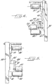
- Take-up mechanism 30 further includes a set of fabric delivery rolls, which as illustrated is a set of three rolls 35 , 36 and 37 arranged generally in the same horizontal plane and which co-act together to form nips therebetween through which the fabric 27 is threaded.
- fabric 27 passes through the nip between rolls 36 and 37 , around the bottom of roll 36 and upwardly through the nip between rolls 35 and 36 and thence around the top and outside of roll 35 and downwardly therefrom to a take-up roll 40 .
- Take-up roll 40 is journaled for free rotation in bearings 41 at opposite ends thereof mounted on the side frame members 32 .
- Take-up roll 40 is contacted and driven in rotation by a driving roll 42 journaled for rotation at its opposite ends in bearings carried by mounting members 43 .
- Mounting members 43 are pivotally mounted at their ends opposite driving roll 42 by pivots 44 on brackets 45 which are, in turn, mounted on side frame members 32 .
- Driving roll 42 is thus free to move upwardly and downwardly about pivots 44 while remaining in contact with the surface of take-up roll 40 or the fabric being wound about roll 40 to drive the roll 40 and the fabric roll being formed thereon by surface contact.
- a pivotal motion inhibitor 46 is pivotally mounted to one of the driving roll mounting members 43 and to one of the brackets 45 to prevent rapid pivotal movement of the drive roll 42 , as when a roll of fabric is removed from the take-up roll 40 and the drive roll 42 returns to the starting position.
- Delivery roll 35 is journaled at its opposite ends in bearings 50 mounted on side frame members 32 ( Figure 3).
- Roll 35 has mounted thereon a pair of swing arms 51 which are journaled for pivotal movement about the axis of delivery roll 35 .
- Swing arms 51 extend outwardly from roll 35 substantially horizontally and terminate in free ends.
- Swing arms 51 include longitudinal slots 52 extending horizontally therein and being open at the free ends of swing arms 51 .
- Delivery roll 36 is journaled at its opposite ends in bearings 53 which are square in outer configuration and are received in the slots 52 in swing arms 51 . Accordingly, delivery roll 36 is mounted for rotation in bearings 53 while bearings 53 are held against rotation in slots 52 in swing arms 51 . Similarly, delivery roll 37 is journaled at its opposite ends in square bearings 54 also received in slots 52 in swing arms 51 . Delivery rolls 36 and 37 are spring biased into contact with each other and roll 36 into contact with roll 35 by compression springs 55 pressing against square bearings 54 at one end thereof and against end caps 56 on swing arms 51 at their other ends. Pressure relief mechanisms 57 are provided for relieving the pressure of springs 55 on the delivery rolls 36 and 37.
- delivery rolls 35, 36 and 37 are driven by a drive means which includes a variable speed, out-rotor type DC motor 60, such as, a motor made by Itoh Electric, K.K.
- Motor 60 drives reduction gearing 61 which, in turn, drives delivery roll 35 .
- Motor 60 and gearing 61 are housed within the hollow delivery roll 35 and are mounted on a stub shaft 62 which also mounts roll 35 for rotation.
- a spur gear 63 is mounted on one end of delivery roll 35 for rotation therewith.
- Spur gear 63 meshes with a spur gear 64 mounted on one end of delivery roll 36 for rotating delivery roll 36 synchronously with delivery roll 35 .
- Spur gear 64 meshes with a spur gear 65 drivingly mounted on one end of delivery roll 37 . Accordingly, delivery rolls 35, 36 and 37 are driven in rotation by variable speed motor 60 through reduction gearing 61 and spur gears 63 , 64 and 65 .
- drive roll 42 is also driven in rotation by an identical motor 66 and reduction gearing (not shown) to motor 60 and reduction gearing 61 which drives delivery roll 35 .
- Motor 66 is mounted within the hollow drive roll 42 ( Figure 4).
- the fabric 27 will pass downwardly through the cylinder 26 to the delivery rolls 36 and 37 where the same is flattened and passes through the nip between delivery rolls 36 and 37 and then through the nip between delivery rolls 35 and 36 downwardly around the periphery of drive roll 42 and between the nip between take-up roll 40 and drive roll 42 to be wound about take-up roll 40 . If the tension of fabric 27 increases above a predetermined desired amount, the swing arms 51 will pivot in a counter clockwise direction as seen in Figure 2, with the free outer ends thereof moving upwardly.
- a proximity sensing device 70 is mounted by a bracket 71 beneath the outer free end of one of the swing arms 51 .
- the proximity sensor 70 senses the pivotal movement of the swing arm 51 from its normal operating position and also senses the distance that the free end of the swing arm 51 has moved from its normal position.
- Bracket 71 is mounted at its other end on a block 72 which, in turn, is mounted on one of the side frame members 32 .
- a leaf spring 73 is carried by the top of block 72 and is positioned beneath the outer free end of swing arms 51 to bias swing arm 51 toward its normal operating position while permitting some limited downward movement of the free ends of swing arms 51 upon a reduction in the tension in fabric 27 from the normal desired tension therein. Upon such limited downward movement, the proximity sensor 70 will sense the shorting of the distance between the free end of swing arm 51 and proximity sensor 70 which is indicative of a decrease in the tension in fabric 27 .
- a load cell 74 may be interposed between the free end of swing arm 51 and the side frame member 32 .
- Load cell 74 normally is loaded a predetermined amount by the swing arm 51 when the swing arm is in its normal operating position maintaining the predetermined desired tension in the fabric 27 .
- the swing arms 51 will pivot upwardly about the delivery roll 35 and the predetermined initial loading of load cell 74 will be reduced by a decreasing amount corresponding to the increase in the amount of tension in fabric 27 .
- the load on load cell 74 will be increased by an amount concomitant with the decrease in tension in fabric 27 .
- Both proximity sensor 70 and load cell 74 generate electrical signals indicative of increases or decreases in the tension in fabric 27 .
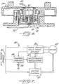
- Control means generally indicated at 80 in Figure 7, is provided for controlling the speed of motor 60 driving delivery rolls 35 , 36 and 37 in accordance with the signals generated by the tension sensing means, i.e. proximity sensor 70 or load cell 74 , of the present invention.
- the control means 80 includes a motor control 81 which is connected to a suitable power source 82 , such as a DC power source.
- Motor control 81 is connected to motor 60 and receives a feedback signal from motor 60 concerning the state of operation of motor 60 at any given time.
- Control means 80 further includes a control circuit 83 which is connected, in a manner not shown, to the proximity sensor 70 or load cell 74 for receiving signals from these fabric tension sensing means.
- Control circuit 83 includes a potentiometer or variable resistor 84 , whereby control circuit 83 may be preset for a predetermined normal or desired fabric tension.
- the control circuit 83 compares the signal from the fabric tension sensing means with the preset reference value set by potentiometer 84 and any deviation from this preset reference value is fed to a pulse width modulator controller 85 .
- PWM controller 85 is also connected to the motor control 81 for receiving feedback signals from motor 60 .
- PWM controller 85 compares the deviation signal from control circuit 83 with the feedback signal from motor control 81 and generates a power signal to motor 60 through a three phase full wave bridge 86 , the output side of which is connected to motor 60 . This power signal determines the speed at which motor 60 will drive the delivery roll 35 and delivery rolls 36 and 37 .
- the control means 80 will cause motor 60 to drive delivery roll 35 , 36 and 37 faster until the fabric tension equals the initially set, reference value. Once the feedback signal from the fabric tension sensing means is equal to the reference value then no deviation signal will be sent to the PWM controller 85 and the motor 60 will operate at a constant speed. If the signal from the fabric tension sensing means 70 or 74 indicates an increase in tension above the initially set reference value, the control means 80 will cause the motor 60 to drive the delivery rolls at a slower speed until the tension in the fabric is reduced to the reference value.
- Motor 66 drives the drive roller 42 at a uniform torque. Accordingly, the fabric 27 is wound up on the take-up roll 40 at the uniform fabric tension at which the fabric 27 is delivered from the delivery rollers 35 , 36 and 37 .
- Power transmitting device 90 is housed in bearing box 34 that mounts the lower portion of the take-up mechanism 30 for rotation.
- Power transfer device 90 includes an input line 92 which is connected to a contact ring 93 rotating on a shaft 94 in contact with a carbon brush 95 .
- the vertical shaft 94 is mounted in a hollow box 96 which, in turn, is mounted on the lower portion of bearing box 34 .
- the carbon brush 95 is mounted on the cover portion of bearing box 34 for rotation therewith as the take-up mechanism 30 rotates with the cylinder 26 .
- An output lead 97 is connected at one end to the carbon brush 95 and at its other end to motors 60 and 66 and to the fabric tension sensing means, such as proximity sensor 70 or load cell 74 .
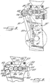
- a fabric take-up mechanism 30' includes side frame members 32' mounting delivery rolls 35' , 36' and 37' and a fabric take-up roll 40' .
- the delivery rolls 35' , 36' and 37' are mounted and are driven in the same manner as were delivery rolls 35 , 36 and 37 in the embodiment illustrated in Figures 1 through 3.
- a drive roll 42' is journaled for rotation in slots 100 formed in the side frame members 32' for sliding vertical movement along the slots 100 as the fabric roll being formed around take-up roll 40' increases in diameter.
- Drive roll 42' is driven by a chain 101 which is trained about an idler sprocket 102 at its lower end.
- Idler sprocket 102 is mounted for rotation on a shaft 103 which is journaled within suitable bearings mounted on the side frame member 32' .
- Drive chain 101 is trained at its upper end about a drive sprocket 104 mounted on a shaft 105 also journaled for rotation in bearings mounted on side frame member 32' .
- Shaft 105 has a spur gear 106 drivingly mounted thereon which meshes with the spur gear 63' mounted for rotation on delivery roll 35' .
- Spur gear 63' drives spur gear 106 and thereby drives sprocket 104 and chain 101 .
- a sprocket 107 is mounted on drive roll 42' and rotates drive roll 42' in timed relation to the rotation of delivery roll 35' . It is noted that slots 100 are parallel to the drive chain 101 such that the sprocket 107 on drive roll 42' remains in contact with the drive chain 101 as drive roll 42 ' moves along slots 100 .
- the speed at which the drive roll 42' is driven is such that drive roll 42' rotates slightly faster than the delivery rolls 35' , 36' and 37' , taking into consideration the reduction of the tension in the fabric that is forcefully delivered by the delivery rolls 35' , 36' and 37' .
- a sprocket 110 is mounted on the end of the shaft of delivery roll 35'' and drives a sprocket chain 111 which is trained at its lower end about a driven sprocket 112 on the shaft of one of a pair of friction drive rolls 113 (only one of which is shown in Figure 15).
- the disclosure of United States Patent No. 4,671,083 is incorporated herein by reference.
- Take-up roll 40'' is journaled at its opposite ends in square bearings 114 which are slidably mounted in vertical slots formed in or on the side frame members 32'' .
- FIG. 9 there is shown still another embodiment of a tension sensing means in accordance with the present invention.
- delivery rolls 135 , 136 and 137 are in a generally horizontal arrangement.
- Roll 135 is journaled for rotation at its opposite ends on a pair of swing arms 151 .
- Swing arms 151 are fixedly mounted at one end 151a thereof by bolts 152 on the side frame members 132 .
- Swing arms 151 have a reduced neck portion 151b which has sufficient flexibility therein to permit some upward and downward flexure movement of the free end portions 151c of swing arms 151 upon fluctuations in the tension in the fabric 127 .
- Rolls 136 and 137 are journaled at their opposite ends in square bearings 153 , 154 mounted in slots 152 in the swing arms 151 .
- a coil spring 155 presses the rolls 136 and 137 together and roll 136 against roll 135 , while a roll separating means 157 is provided for separating the rolls as desired.
- a pair of strain gauges 160 are mounted on top and bottom sides of the neck portions 151b of the swing arms 151 for compression upon vertical movement of the free ends 151c thereof and flexure of the necks 151b .
- the deformation of the strain gauges 160 is converted to an electrical signal which is then fed to the control circuit 83 of the control means 80 illustrated in Figure 7.
- the stationary delivery roll 235 is mounted in the center of the three delivery roll arrangement with the movable delivery rolls 236 and 237 mounted on opposite sides thereof.
- the delivery roll 235 is journaled for rotation at its opposite ends on swing arms 251 fixedly mounted on side frame members 232 by bolts 252 , 253 at one end 251a thereof. Swing arms 251 have neck portions 251b which flex upon fluctuations in tension of the fabric.
- Delivery rolls 236 and 237 are journaled for rotation at their opposite ends on pivotal mounting members 201 , 202 which are pivotally mounted at their lower ends on swing arms 251 by pivot pins 203 , 204 .
- Pivotal mounting members 201 and 202 have upstanding studs 205 , 206 at their free upper ends which are connected by a tension spring 207 to bias delivery rolls 236 and 237 against the center delivery roll 235 .
- Pivotal mounting members 201 and 202 have cam portions 236a and 237a that are contiguous to each other above center mounted delivery roll 235 .
- Cam members 210 are mounted for vertical movement on swing arms 251 and have operating levers 211 connected thereto for manual vertical movement of the cam members 210 upwardly and downwardly for contact with the cam portions 236a and 237a to move the pivotal mounting members 201 and 202 away from each other and to thereby move the delivery rolls 236 and 237 away from the center mounted delivery roll 235 .
- strain gauges are mounted on opposite sides of the neck portion 251b of swing arms 251 for sensing variations in the tension of the fabric, as described in connection with the embodiment shown in Figure 9.
- the drive means for the delivery rolls 235 , 236 and 237 includes a variable speed motor 260 suitably mounted on a side frame member 232 .
- Motor 260 drives a reduction gearing including a drive gear 261 on the output shaft thereof.
- Drive gear 261 meshes with a suitable spur gear 262 mounted for rotation on a stub shaft 263 journaled for rotation in suitable bearings (not shown) mounted on side frame member 232 .
- Stub shaft 263 also includes a smaller spur gear 264 thereon which meshes with a larger diameter spur gear 265 mounted for rotation on a stub shaft 266 journaled for rotation in bearings carried by the side frame member 232 .
- Stub shaft 266 has mounted thereon a smaller diameter drive gear 267 which meshes with a spur gear 268 mounted on the shaft of the delivery roll 235 .
- FIG 14 there is illustrated the opposite ends of the delivery rolls 235 , 236 and 237 .
- the shaft of delivery roll 235 has a spur gear 270 mounted thereon for rotation therewith which meshes with a spur gear 271 mounted on the shaft of delivery roll 236 and a spur gear 272 mounted on the shaft of delivery roll 237 .
- Delivery rolls 236 and 237 are thereby driven in synchronism with the delivery roll 235 .
- the motor 260 is controlled by a control circuit as illustrated in Figure 7 and is responsive to the tension sensing means for controlling the speed at which motor 260 drives the delivery rolls 235 , 236 and 237 . Any of the drive mechanisms for the take-up roll may be used with the embodiment of delivery rolls illustrated in Figures 10 through 14.
Landscapes
- Engineering & Computer Science (AREA)
- Textile Engineering (AREA)
- Knitting Machines (AREA)
Applications Claiming Priority (4)
| Application Number | Priority Date | Filing Date | Title |
|---|---|---|---|
| JP297978/92 | 1992-10-09 | ||
| JP29797892 | 1992-10-09 | ||
| JP4351754A JPH06173146A (ja) | 1992-10-09 | 1992-12-07 | 丸編機における巻取部の駆動装置 |
| JP351754/92 | 1992-12-07 |
Publications (1)
| Publication Number | Publication Date |
|---|---|
| EP0591988A1 true EP0591988A1 (fr) | 1994-04-13 |
Family
ID=26561324
Family Applications (1)
| Application Number | Title | Priority Date | Filing Date |
|---|---|---|---|
| EP93116325A Withdrawn EP0591988A1 (fr) | 1992-10-09 | 1993-10-08 | Dispositif d'enroulement d'étoffe pour métier à tricoter circulaire |
Country Status (4)
| Country | Link |
|---|---|
| US (1) | US5381676A (fr) |
| EP (1) | EP0591988A1 (fr) |
| JP (1) | JPH06173146A (fr) |
| KR (1) | KR940009401A (fr) |
Cited By (7)
| Publication number | Priority date | Publication date | Assignee | Title |
|---|---|---|---|---|
| WO2001048288A1 (fr) * | 1999-12-24 | 2001-07-05 | Santoni S.P.A. | Appareil et procede permettant de controler le poids d'un tissu produit par une machine a textile, notamment par un metier a tricoter circulaire |
| RU2179603C1 (ru) * | 2001-05-30 | 2002-02-20 | Санкт-Петербургский государственный университет технологии и дизайна | Механизм оттяжки трикотажного полотна на кругловязальной машине |
| EP1087048A3 (fr) * | 1999-09-24 | 2003-07-09 | Precision Fukuhara Works, Ltd. | Dispositif de réglage de la densité d'étoffe et mécanisme de contrôle d'alimentation en fil pour un métier à tricoter circulaire |
| EP1731649A1 (fr) | 2005-06-03 | 2006-12-13 | Pai Lung Machinery Mill Co., Ltd. | Mécanisme d'enroulement d'un tricot haut sur jambes à haute vitesse avec dispositif pour établir une tension d'enroulement constante |
| DE19833509B4 (de) * | 1997-07-25 | 2008-08-28 | Santoni S.P.A. | Rundstrickmaschine mit einer Zugvorrichtung für Strickware |
| CN100507115C (zh) * | 2005-06-07 | 2009-07-01 | 佰龙机械厂股份有限公司 | 悬臂式高脚卷布机 |
| CN102704183A (zh) * | 2011-03-26 | 2012-10-03 | 卡尔迈尔纺织机械制造有限公司 | 从纺织机尤其经编机中引出面状的纺织的织物幅面的装置 |
Families Citing this family (12)
| Publication number | Priority date | Publication date | Assignee | Title |
|---|---|---|---|---|
| EP0923653A1 (fr) * | 1996-07-29 | 1999-06-23 | Mayer Industries, Inc. | Machine a tricoter circulaire avec ensemble attracteur pour appliquer une tension constante au tissu tricote |
| SE517044C2 (sv) * | 1997-03-20 | 2002-04-09 | Texo Ab | Tygbomsarrangemang för vävmaskin |
| US6082143A (en) * | 1997-08-14 | 2000-07-04 | Sara Lee Corporation | Circular knitting machine |
| DE69819861T2 (de) * | 1998-01-23 | 2004-11-04 | Santoni S.P.A. | Vorrichtung zum Liefern eines elastisch ausdehnbaren Fadens zu Strickmaschinen |
| DE19916669A1 (de) * | 1999-04-14 | 2000-11-02 | Stahlecker Fritz | Vorrichtung zum Aufspulen von Fäden auf Spulen mit wilder Kreuzwicklung |
| KR100331966B1 (ko) * | 1999-10-23 | 2002-04-10 | 윤기룡 | 염색된 직물의 직물권취장치 |
| IT1316321B1 (it) * | 2000-02-01 | 2003-04-10 | Matec Spa | Dispositivo e procedimento di regolazione della forza di tiraggio dicalze in macchine tessili circolari |
| JP2011088709A (ja) * | 2009-10-22 | 2011-05-06 | Hakuryu Kikaisho Kofun Yugenkoshi | ウエブ裁断装置の巻き取り機構 |
| US7836732B1 (en) * | 2009-11-06 | 2010-11-23 | Pai Lung Machinery Mill Co., Ltd. | Method and apparatus for lowering and folding fabric at amount same as fabric knitted and unloaded by a circular knitting machine |
| JP2014095157A (ja) * | 2012-11-07 | 2014-05-22 | Precision Fukuhara Works Ltd | 丸編機の巻取制御方法および装置 |
| KR101648724B1 (ko) * | 2014-10-29 | 2016-08-17 | 주식회사 인팩 | 원단 공급장치 |
| KR101933126B1 (ko) * | 2016-02-18 | 2019-03-15 | 주식회사 선진피앤씨 | 소재 공급장치 |
Citations (5)
| Publication number | Priority date | Publication date | Assignee | Title |
|---|---|---|---|---|
| US3842627A (en) * | 1969-07-28 | 1974-10-22 | Travis Mills Corp | Means for rolling up tubular fabric produced by a circular knitting machine |
| EP0148727A1 (fr) * | 1983-12-06 | 1985-07-17 | Battelle Memorial Institute | Mécanisme d'enroulement d'un tissu pour métier à tricoter circulaire |
| US4671083A (en) * | 1985-01-25 | 1987-06-09 | Precision Fukuhara Works, Ltd. | Driving apparatus in take up unit of circular knitting machine |
| EP0261049A2 (fr) * | 1986-09-18 | 1988-03-23 | José Abril Cullell | Dispositif de tirage d'un métier à tricoter rectiligne |
| GB2246369A (en) * | 1990-07-24 | 1992-01-29 | Chin Yung Lin | Cloth winding device for textile machine |
Family Cites Families (9)
| Publication number | Priority date | Publication date | Assignee | Title |
|---|---|---|---|---|
| US4027506A (en) * | 1975-10-14 | 1977-06-07 | Firma C. Terrot Sohne | Draw-off and take-up arrangement for circular knitting machines |
| DE2631223B2 (de) * | 1976-07-12 | 1979-03-29 | C. Terrot Soehne Gmbh & Co, 7000 Stuttgart | Warenabzugvorrichtung |
| US4233825A (en) * | 1978-05-05 | 1980-11-18 | Glitsch, Inc. | Knitting machine |
| US4236390A (en) * | 1978-11-09 | 1980-12-02 | Terrot Strickmaschinen Gmbh | Knitting machine |
| IT1191352B (it) * | 1986-03-14 | 1988-03-16 | Emm Srl | Dispositivo per la tesatura del tessuto in formazione in una macchina automatica rettilinea per maglieria |
| DE3638374C1 (de) * | 1986-11-11 | 1988-04-21 | Schieber Universal Maschf | Warenabzugseinrichtung an Flachstrickmaschinen |
| IT1217250B (it) * | 1988-04-29 | 1990-03-14 | Mecmor Spa | Dispositivo di tiraggio del tessuto a maglia in una macchina circolare per maglieria,in particolare del tipo a grande diametro |
| JPH0665780B2 (ja) * | 1989-10-04 | 1994-08-24 | 株式会社島精機製作所 | 編地引下げ装置 |
| JPH04289251A (ja) * | 1991-03-18 | 1992-10-14 | Yoichi Inamoto | 丸編機における編地送り用ロールへの動力伝達装置 |
-
1992
- 1992-12-07 JP JP4351754A patent/JPH06173146A/ja active Pending
-
1993
- 1993-05-19 KR KR1019930008563A patent/KR940009401A/ko not_active Withdrawn
- 1993-09-29 US US08/128,807 patent/US5381676A/en not_active Expired - Fee Related
- 1993-10-08 EP EP93116325A patent/EP0591988A1/fr not_active Withdrawn
Patent Citations (5)
| Publication number | Priority date | Publication date | Assignee | Title |
|---|---|---|---|---|
| US3842627A (en) * | 1969-07-28 | 1974-10-22 | Travis Mills Corp | Means for rolling up tubular fabric produced by a circular knitting machine |
| EP0148727A1 (fr) * | 1983-12-06 | 1985-07-17 | Battelle Memorial Institute | Mécanisme d'enroulement d'un tissu pour métier à tricoter circulaire |
| US4671083A (en) * | 1985-01-25 | 1987-06-09 | Precision Fukuhara Works, Ltd. | Driving apparatus in take up unit of circular knitting machine |
| EP0261049A2 (fr) * | 1986-09-18 | 1988-03-23 | José Abril Cullell | Dispositif de tirage d'un métier à tricoter rectiligne |
| GB2246369A (en) * | 1990-07-24 | 1992-01-29 | Chin Yung Lin | Cloth winding device for textile machine |
Cited By (8)
| Publication number | Priority date | Publication date | Assignee | Title |
|---|---|---|---|---|
| DE19833509B4 (de) * | 1997-07-25 | 2008-08-28 | Santoni S.P.A. | Rundstrickmaschine mit einer Zugvorrichtung für Strickware |
| EP1087048A3 (fr) * | 1999-09-24 | 2003-07-09 | Precision Fukuhara Works, Ltd. | Dispositif de réglage de la densité d'étoffe et mécanisme de contrôle d'alimentation en fil pour un métier à tricoter circulaire |
| WO2001048288A1 (fr) * | 1999-12-24 | 2001-07-05 | Santoni S.P.A. | Appareil et procede permettant de controler le poids d'un tissu produit par une machine a textile, notamment par un metier a tricoter circulaire |
| RU2179603C1 (ru) * | 2001-05-30 | 2002-02-20 | Санкт-Петербургский государственный университет технологии и дизайна | Механизм оттяжки трикотажного полотна на кругловязальной машине |
| EP1731649A1 (fr) | 2005-06-03 | 2006-12-13 | Pai Lung Machinery Mill Co., Ltd. | Mécanisme d'enroulement d'un tricot haut sur jambes à haute vitesse avec dispositif pour établir une tension d'enroulement constante |
| CN100507115C (zh) * | 2005-06-07 | 2009-07-01 | 佰龙机械厂股份有限公司 | 悬臂式高脚卷布机 |
| CN102704183A (zh) * | 2011-03-26 | 2012-10-03 | 卡尔迈尔纺织机械制造有限公司 | 从纺织机尤其经编机中引出面状的纺织的织物幅面的装置 |
| CN102704183B (zh) * | 2011-03-26 | 2015-11-25 | 卡尔迈尔纺织机械制造有限公司 | 从纺织机尤其经编机中引出面状的纺织的织物幅面的装置 |
Also Published As
| Publication number | Publication date |
|---|---|
| KR940009401A (ko) | 1994-05-20 |
| US5381676A (en) | 1995-01-17 |
| JPH06173146A (ja) | 1994-06-21 |
Similar Documents
| Publication | Publication Date | Title |
|---|---|---|
| US5381676A (en) | Fabric take-up mechanism for circular knitting machines | |
| US6301938B1 (en) | Automatic fabric density adjusting device and yarn feeding control mechanism for a circular knitting machine | |
| KR100583685B1 (ko) | 코일재료 피딩장치 | |
| TW494154B (en) | Device for the wind up of a knitted material web | |
| US4671083A (en) | Driving apparatus in take up unit of circular knitting machine | |
| CN100434585C (zh) | 用于将弹性纱喂入纺织机的装置和方法 | |
| CN102605541B (zh) | 织品导向件的控制方法和采用它的摆落卷取装置 | |
| GB2092186A (en) | Method of terminating thread winding on ring spinning or ring doubling machines and ring spinning or ring doubling machine for performing this method | |
| US4858843A (en) | Fabric web delivery apparatus | |
| JPH11322195A5 (fr) | ||
| EP0652314A1 (fr) | Procédé et dispositif pour ajuster la densité de maille dans un métier à tricoter circulaire | |
| EP0440481B1 (fr) | Dispositif d'entraînement d'une unité d'enroulement à un métier à tricoter circulaire | |
| CN214165463U (zh) | 供料装置及包装机 | |
| US6151925A (en) | Methods and systems for positively feeding yarn to circular knitting machines | |
| EP0622486A1 (fr) | Dispositif enrouleur d'étoffe pour métiers à tricoter circulaires | |
| CN212799063U (zh) | 力矩传感器及收丝机 | |
| JPH0672348B2 (ja) | ヤ−ン送給装置 | |
| US6450212B1 (en) | Solid state web take-up control | |
| JP3269327B2 (ja) | 巻取機 | |
| CN116534666A (zh) | 使线状材料保持恒定张力的锭子张力控制装置及锭子架 | |
| CN111792420B (zh) | 一种蕾丝上料机 | |
| EP0711366B1 (fr) | Procede et machine de fabrication de bandes elastiques et bandes ainsi obtenues | |
| CN206467358U (zh) | 棉卷压力调节装置 | |
| JP4484372B2 (ja) | ビーム送り出し装置及びフィラメントを送り出す方法 | |
| JPH0268343A (ja) | 横編機用引出し装置 |
Legal Events
| Date | Code | Title | Description |
|---|---|---|---|
| PUAI | Public reference made under article 153(3) epc to a published international application that has entered the european phase |
Free format text: ORIGINAL CODE: 0009012 |
|
| AK | Designated contracting states |
Kind code of ref document: A1 Designated state(s): DE ES GB IT |
|
| 17P | Request for examination filed |
Effective date: 19940825 |
|
| 17Q | First examination report despatched |
Effective date: 19960726 |
|
| GRAG | Despatch of communication of intention to grant |
Free format text: ORIGINAL CODE: EPIDOS AGRA |
|
| GRAG | Despatch of communication of intention to grant |
Free format text: ORIGINAL CODE: EPIDOS AGRA |
|
| GRAH | Despatch of communication of intention to grant a patent |
Free format text: ORIGINAL CODE: EPIDOS IGRA |
|
| GRAH | Despatch of communication of intention to grant a patent |
Free format text: ORIGINAL CODE: EPIDOS IGRA |
|
| STAA | Information on the status of an ep patent application or granted ep patent |
Free format text: STATUS: THE APPLICATION IS DEEMED TO BE WITHDRAWN |
|
| 18D | Application deemed to be withdrawn |
Effective date: 20000503 |