EP0591995B1 - Dispositif et méthode pour orienter une pièce courbée - Google Patents
Dispositif et méthode pour orienter une pièce courbée Download PDFInfo
- Publication number
- EP0591995B1 EP0591995B1 EP93116345A EP93116345A EP0591995B1 EP 0591995 B1 EP0591995 B1 EP 0591995B1 EP 93116345 A EP93116345 A EP 93116345A EP 93116345 A EP93116345 A EP 93116345A EP 0591995 B1 EP0591995 B1 EP 0591995B1
- Authority
- EP
- European Patent Office
- Prior art keywords
- needle
- pusher
- die
- workpiece
- curved
- Prior art date
- Legal status (The legal status is an assumption and is not a legal conclusion. Google has not performed a legal analysis and makes no representation as to the accuracy of the status listed.)
- Expired - Lifetime
Links
- 238000000034 method Methods 0.000 title claims description 7
- 238000003825 pressing Methods 0.000 claims description 50
- 230000007246 mechanism Effects 0.000 claims description 24
- 239000011248 coating agent Substances 0.000 claims description 3
- 238000000576 coating method Methods 0.000 claims description 3
- 230000004913 activation Effects 0.000 claims 3
- 230000003213 activating effect Effects 0.000 claims 1
- 230000000063 preceeding effect Effects 0.000 claims 1
- 238000004519 manufacturing process Methods 0.000 description 14
- 238000005520 cutting process Methods 0.000 description 2
- 238000007493 shaping process Methods 0.000 description 2
- 238000002788 crimping Methods 0.000 description 1
- 230000000694 effects Effects 0.000 description 1
- 238000000227 grinding Methods 0.000 description 1
- 239000000463 material Substances 0.000 description 1
- 230000000717 retained effect Effects 0.000 description 1
- 238000001356 surgical procedure Methods 0.000 description 1
Images


Classifications
-
- B—PERFORMING OPERATIONS; TRANSPORTING
- B21—MECHANICAL METAL-WORKING WITHOUT ESSENTIALLY REMOVING MATERIAL; PUNCHING METAL
- B21G—MAKING NEEDLES, PINS OR NAILS OF METAL
- B21G1/00—Making needles used for performing operations
-
- B—PERFORMING OPERATIONS; TRANSPORTING
- B21—MECHANICAL METAL-WORKING WITHOUT ESSENTIALLY REMOVING MATERIAL; PUNCHING METAL
- B21F—WORKING OR PROCESSING OF METAL WIRE
- B21F1/00—Bending wire other than coiling; Straightening wire
Definitions
- the present invention relates to an apparatus for orienting a curved workpiece at a workstation.
- the invention relates to an apparatus for presenting a curved surgical needle blank at a work station in a predetermined orientation during needle manufacture.
- the manufacture of surgical needles involves many processing steps to transform the raw needle stock into a highly precisioned surgical needle product. Some of these processes include straightening, cutting, shaping, grinding, boring, pressing and coating operations.
- an apparatus for needle manufacture which can present a curved needle in a predetermined desired orientation at a workstation. It would also be desirable to provide such an apparatus which can be readily adapted for use with a variety of needle manufacturing processes.
- the present invention is directed to an apparatus for presenting a curved workpiece having curved inner and outer surfaces to a workstation.
- the apparatus comprises frame means, guide means associated with the frame means for receiving a curved workpiece in a generally upright position, first pusher means reciprocally movable in a transverse direction relative to the guide means for engaging and positioning the workpiece with its curved outer surface against a bearing surface of the guide means and second pusher means advanceable within the guide means for slidably advancing the workpiece and for presenting the workpiece in a predetermined rotational orientation at the workstation.
- the apparatus is particularly adapted for use in the manufacture of curved surgical needles.
- the first pusher means defines an arcuate needle engaging surface dimensioned to engage the inner curved surface of the needle during an advancing movement thereof to position the needle against the bearing surface of the guide means.
- the arcuate engaging surface terminates at one end in a first generally horizontal positioning surface and at a second end in a second generally horizontal positioning surface.
- the first and second positioning surfaces are dimensioned to engage the first and second ends of the needle during an advancing movement of the first pusher means towards the guide means to position the needle in the predetermined rotational orientation within the guide means.
- the second pusher means comprises a needle engaging surface having a projecting member extending therefrom.
- the projecting member is positioned and dimensioned to engage the second end of the needle to retain the needle in the predetermined rotational orientation as the needle is advanced to the workstation.
- the projecting member is positioned and dimensioned to permit slight rotational movement of the needle about a center axis of curvature defined thereby as the needle is advanced along its outer curved surface through the guide means. Such rotational movement of the needle positions the needle in the predetermined rotational orientation at the workstation.
- the needle engaging surface of the second pusher means also includes an arcuate surface portion.
- the arcuate surface portion is particularly configured and dimensioned to increase surface contact between the engaging surface of the second pusher means and the outer curved surface of the needle to facilitate advancement of the needle to the workstation.
- the apparatus further includes first and second drive means which are operatively connected to the first and second pusher means, respectively.
- the first drive means provides reciprocal movement to the first pusher means.
- the second drive means advances the second pusher means from an initial needle engaging position to a needle operating position adjacent the workstation.
- the second drive means may also be adapted to further advance the second pusher means from the needle operating position to a needle release position to expel the needle from the workstation.
- the first and second drive means comprise pneumatic means.
- the present invention is also directed to an apparatus for pressing at least a portion of a curved surgical needle.
- This apparatus further comprises side pressing means having die means including first and second die members and die advancing means for advancing at least one of the die members towards the other member to press the needle.
- the die members each define a die face having first, second and third surfaces. The three surfaces are dimensioned and positioned to press the main portion of the needle while preserving the integrity of the pointed and butt ends.
- the present invention is also directed to a method for presenting a curved surgical needle in a predetermined rotational orientation at a workstation.
- the method comprises the steps of placing the curved surgical needle in a generally upright position within a guide channel, advancing a first pusher member in a general transverse direction relative to the guide channel such that the first pusher member engages the inner curved surface of the needle to position the needle in a predetermined rotational orientation with its curved outer surface facing a bearing surface of the guide channel and advancing a second pusher member within the guide channel to advance the needle and present the needle in the predetermined rotational orientation at the workstation.
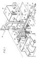
- apparatus 10 for presenting a curved workpiece in a predetermined orientation constructed according to the present invention.
- the apparatus 10 is equipped to perform a pressing operation on a curved surgical needle and will be described in accordance with such operation for exemplative purposes.
- apparatus 10 may be used in conjunction with workstations designed to perform other needle manufacturing processes such as crimping, cutting, sharpening, coating, shaping, etc.
- apparatus 10 may be adapted to accommodate a variety of curved workpieces other than curved surgical needles.
- Apparatus 10 includes frame 12 which supports a vertical pusher mechanism and a horizontal pusher mechanism identified generally by the reference numerals 14, 16 respectively, and a needle nest area identified generally by the reference numeral 18.
- Vertical pusher mechanism 14 includes vertical pusher element 20 which is adapted for reciprocal transverse movement between a retracted position and an extended position. In the extended position, vertical pusher 20 engages a needle received within needle nest 18 and positions the needle in a desired rotational orientation therewithin. Vertical pusher 20 is operatively connected to piston 22. Piston 22 is a component of a drive mechanism which is adapted to provide such transverse movement. In the preferred embodiment, the drive mechanism preferably incorporates a pneumatic system.
- Horizontal pusher mechanism 16 includes horizontal pusher 24 which is housed within a longitudinal slot 26 formed in pusher housing 28. Horizontal pusher 24 advances within slot 26 and into needle nest 18 to engage the needle positioned by vertical pusher 20, and to advance the needle to the workstation for the pressing operation.
- horizontal pusher 24 is also advanceable by a pneumatic system.
- a pneumatically operated piston 30 imparts motion to slide member 32, which is operatively connected to horizontal pusher 24 disposed within pusher housing 28. Consequently, movement of slide member 32 advances the horizontal pusher 24 through needle nest 18 and to the pressing operation.
- Horizontal pusher 24 may be connected to slide member 32 by conventional means.
- the pneumatically operated horizontal pusher mechanism is preferably advanceable through two positions.
- the first position corresponds to a needle processing position wherein horizontal pusher 24 advances the needle from needle nest 18 to the workstation, i.e., where the pressing operation is performed.
- the second position corresponds to a needle release position wherein horizontal pusher 24 is further advanced to expel the needle from the workstation upon completion of the needle pressing step.
- the pneumatic system also includes an adjusting mechanism to control the distance horizontal pusher 24 advances within the apparatus.
- the adjusting mechanism includes the piston stop which is positioned on piston. The location of the piston stop may be adjusted on piston 30, which, accordingly, enables the operator to control the amount of advancing movement of horizontal pusher 24 and the positioning of the needle relative to the workstation.
- This feature provides a means for the operator to control the amount of surface portion of the needle engaged by the pressing surfaces of the dies as will be described below. It also facilitates in the adaption of the apparatus to other manufacturing processes.
- the location of the piston stop on piston 30 may be adjusted by conventional means, e.g., screw means or the like.
- apparatus 10 also includes needle ramp 36 having feeding channel 38 to assist the operator in feeding the surgical needle 100 within needle nest 18.
- the width of feeding channel 38 is substantially equal to or slightly greater than the diameter of the curvature of the needle to retain the needle in the position shown during introduction into needle nest 18.
- Such dimensioning of feeding channel 38 will ensure that the needle is in a generally upright position when received within needle nest 18 with its inner curved surface facing vertical pusher 20.
- Feeding mechanism 39 is positioned adjacent ramp 36.
- Feeding mechanism 39 is adapted to sequentially deliver curved needle blanks to needle nest 18 via channel 38.
- Feeding mechanism may be a hopper mechanism or any other conventional device suitable for this purpose such as a conveyor system.
- Feeding mechanism 39 may also be adapted to directly feed the needles to needle nest 18.
- Apparatus 10 also includes a pressing station 40 disposed adjacent needle nest 18.
- Pressing station 40 includes a pair of removable side pressing dies 42 which are in alignment with needle nest 18 to receive the needle advanced by horizontal pusher 24.
- a hydraulic press 44 advances dies 42 relative to each other to perform the pressing operation.
- Pressing station 40 also includes a die positioning mechanism (not shown) to adjust the vertical positioning of dies 42 relative to needle nest 18. This feature enables the operator to control the vertical positioning of the pressing surfaces of dies 42 relative to the needle so as to provide another means to control the amount of surface portion of the needle engaged by the pressing surfaces during the pressing operation.
- the die positioning mechanism may be in the form of an adjustable plate disposed beneath the dies or any other conventional means suitable for this purpose.
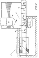
- Needle nest 18 includes channel 46 formed therein to receive needle 100 which had been previously introduced via feeding ramp 36.
- Channel 46 is advantageously dimensioned to receive and retain the curved needle 100 in a generally upright and vertical position, i.e., in a position where the outer curved surface, rather than the point and butt ends of needle 100, can be positioned against bearing surface 50 of channel 46.
- the width of channel 46 is substantially equal to or slightly greater than the largest cross-sectional diameter of needle 100 to maintain the needle in a vertical position as well as to minimize side-to-side rocking motion of the needle during its advancement through the channel.
- Channel 46 is also in alignment with slot 26 of pusher housing 28 to accommodate horizontal pusher 24 and to guide the horizontal pusher during advancement through needle nest 18.
- the lower surface of vertical pusher 20 defines an arcuate bearing surface 48 which engages the inner curved surface of needle 100 during an advancing movement to position the needle against lower bearing surface 50 of channel 46.
- Arcuate bearing surface 48 terminates at a first end thereof in a first horizontal positioning surface 52 and at a second end thereof in a second horizontal positioning surface 54.
- Positioning surfaces 52, 54 are adapted to engage each end of needle blank 100 during a downward movement of vertical pusher 20 to properly orient the needle blank within needle nest 18 in a manner so that it may be subsequently engaged by horizontal pusher 24.
- first and second positioning surfaces 52, 54 engage the pointed and butt ends of needle blank 100, respectively.
- Arcuate bearing surface 48 of vertical pusher 20 preferably defines a radius of curvature which is slightly less than the radius of curvature of needle 100. Such particular dimensioning of arcuate surface 48 will decrease the potential for locking engagement between the arcuate surface and the inner curved surface of needle 100 during a downward engaging movement of vertical pusher 20, and, accordingly, minimize the potential that the needle will ride up with the vertical pusher as the pusher retracts to its initial retracted position.
- apparatus 10 also possess a vacuum source 56 disposed beneath channel 46 of needle nest 18 and in alignment with vertical pusher 20.
- Vacuum source 56 provides a generally vertical flow of air (as shown by the arrows) towards lower bearing surface 50 of channel 46, which air flow communicates through perforations 58 formed in the lower bearing surface of the channel. This air flow assists in retaining needle 100 against bearing surface 50 during a retracting movement of vertical pusher 20. It is also possible for vacuum source 56 to extend along the length of channel 46 within needle nest 18 to assist in retaining needle 48 against bearing surface 50 during advancement to pressing operation 40.
- Needle bearing surface 60 includes a projecting member 62 at its upper portion which engages the butt end of needle 100 during advancement of horizontal pusher 24 through channel 46 of needle nest 18. Projecting member 62 is appropriately dimensioned to prevent rotational movement of needle 100 as the needle is advanced to side pressing station 40 so as to present the needle in a predetermined rotational orientation within dies 42 as will be discussed below. Needle bearing surface 60 is preferably slightly arcuately-shaped. Such configuration increases the surface contact between bearing surface 60 and the outer curved surface of needle 100 to facilitate advancement of the needle through channel 46.
- apparatus 10 is shown in its unactuated position with needle 100 placed within channel 46 of needle nest 18 via ramp 36. Needle 100 is received within channel 46 in a generally upright position with its inner curved surface facing bearing surface 48 of vertical pusher 20. It is to be noted, however, that needle 100 is most likely in a somewhat misaligned position as shown and may or may not be in engagement with lower bearing surface 50 of channel 46.
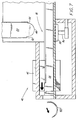
- Actuation of apparatus 10 initially effects movement of vertical pusher 20 from its initial retracted position to an extended position.
- bearing surface 48 of vertical pusher 20 engages the inner curved surface of needle 100 and positions the needle against lower bearing surface 50 of channel 46, while positioning surfaces 52, 54 engage the pointed and butt ends of needle 100, respectively, to position the needle in a desired rotational orientation within needle nest 18 for subsequent engagement by horizontal pusher 24.
- FIG. 3 illustrates vertical pusher 20 in the fully extended position and needle 100 in the desired rotational orientation with its outer curved surface in contact with bearing surface 50 of channel 46.
- vertical pusher 20 is shown in its retracted position while horizontal pusher 24 is shown advanced and engaged with needle 100 in nest 18.
- needle 100 is retained against bearing surface 50 of channel 46 by the air flow created by vacuum source 56 and prevented from riding up with the vertical pusher by the relative dimensioning of arcuate bearing surface 48 and the inner curved surface of needle 100.
- horizontal pusher 24 further advances through needle nest 18 to move needle 100 towards dies 42.
- the needle tends to rotate about its center of curvature in a counterclockwise direction due to the frictional forces realized between the contacting portion of the outer curved surface of the needle and bearing surface 50 of channel 46.
- projecting member 62 of horizontal pusher 24 engages the butt end of needle 100 to retain the needle in the desired orientation. This ensures that needle 100 is presented in its proper rotational orientation within dies 42 at the pressing station 40 as shown in FIG. 6.
- vertical pusher element 20 and horizontal pusher element 24 position and transport needle 100 in a desired rotational orientation within dies 42 for the pressing operation.
- the downward engaging movement of vertical pusher 20 positions needle 100 in a desired rotational orientation while horizontal pusher 24 retains the needle 100 in this desired orientation during advancement to the pressing operation.
- projection 62 of horizontal pusher 24 may be appropriately dimensioned and positioned to permit slight rotational movement of needle 100 such that the needle assumes the desired rotational orientation during advancement along its outer curved surface towards pressing operation 40. Therefore, in accordance with this embodiment, vertical pusher 20 positions needle 100 within channel 46 in a generally oriented manner while horizontal pusher 24 positions the needle in the precise desired predetermined rotational orientation during advancement towards dies 42.
- the pressing mechanism 40 is activated to advance the dies relative to each other to strike the needle. Thereafter, needle 100 is removed from within dies by further advancement of horizontal pusher 24, which accordingly, expels the needle from within dies 42 as shown in FIG. 7.
- Die member 42 defines a die face having three surfaces, namely pressing surface 64, first tapered surface 66 and second tapered surface 68.
- Pressing surface 64 is dimensioned to engage the main portion of needle 100 during the pressing operation to form generally straight pressed surfaces on the needle. The pressed surfaces facilitate grasping of needle 100 with a grasping instrument during surgery.
- First tapered surface 66 is dimensioned to accommodate the pointed end of needle 100 during the pressing operation to prevent the needle point from being engaged by the die faces to preserve the integrity of the pointed end.
- second tapered surface 68 is dimensioned to accommodate the butt end of the needle 100 during the pressing operation to prevent the butt end from being engaged by the die faces as well.
- the range of longitudinal movement of horizontal pusher 24 may be adjusted by altering the location of piston stop 34 on piston 30. (see FIG. 1). Accordingly, the positioning of needle 100 relative to dies 42 may also be adjustable so as to control the amount of surface portion engaged by pressing surfaces 64 of the dies. For example, in FIG. 8, the piston stop is adjusted to advance needle 100 such that the needle point is a distance "a1" from pressing surface 64.
- FIG. 9 illustrates needle 100 in an advanced position within dies 42 relative to the position of the needle within the dies in FIG. 8.
- the pressing surfaces engage a smaller portion of the needle surface as compared to the surface portion engaged by the dies when the needle is in the position shown in FIG. 8. It is also to be noted that the horizontal positioning of dies 42 may also be varied as previously described to provide another means to control the amount of surface portion engaged by the pressing surfaces.
- Apparatus 10 preferably includes a control mechanism (not shown) for controlling the sequential operation of the vertical pusher 20, the horizontal pusher 24 and pressing station 40.
- the control mechanism may be a microprocessor of a known type which fully automates the operation of apparatus 10.
- Apparatus 10 may be adapted to present a variety of different sized curved needles to a workstation.
- Vertical and horizontal pusher elements are readily removable from the apparatus and may be replaced with other comparable pusher elements having different dimensional features so as to accommodate different sized needles.
- the apparatus is not limited in terms of its use with a side pressing mechanism, but, can be readily adapted for use with other needle manufacturing operations.
Landscapes
- Engineering & Computer Science (AREA)
- Mechanical Engineering (AREA)
- Surgical Instruments (AREA)
- Infusion, Injection, And Reservoir Apparatuses (AREA)
Claims (18)
- Appareil pour présenter une pièce courbée (100) ayant des surfaces courbées interne et externe à un poste de travail (40), qui comprend :un moyen de châssis (12) ;un moyen de guidage (46) associé audit moyen de châssis pour recevoir une pièce courbée dans une position généralement debout ;un premier moyen de poussoir (14) déplaçable suivant un mouvement de va-et-vient dans une direction transversale relativement audit moyen de guidage pour venir en prise avec et positionner la pièce avec sa surface extérieure courbée contre une surface de support (50) dudit moyen de guidage ; etun deuxième moyen de poussoir (16) pouvant être amené à avancer dans ledit moyen de guidage pour faire avancer d'une manière coulissante la pièce et pour présenter la pièce selon une orientation de rotation prédeterminée au poste de travail (40).
- Appareil selon la revendication 1, comportant en outre un premier moyen d'entraínement (22) relié opérationnellement audit premier moyen de poussoir (14) pour conférer un mouvement de va-et-vient audit premier moyen de poussoir, et un deuxième moyen d'entraínement (30) opérationnellement relié audit deuxième moyen de poussoir (16) pour faire avancer ledit deuxième moyen de poussoir d'une position initiale de mise en prise avec la pièce à une position de fonctionnement de pièce adjacente au poste de travail (40), ledit deuxième moyen d'entraínement (30) étant apte à faire avancer en outre ledit deuxième moyen de poussoir de ladite position de fonctionnement de pièce à une position de relâchement de pièce pour expulser l'aiguille du poste de travail.
- Appareil selon la revendication 1 ou 2, où la pièce est une aiguille chirurgicale courbée (100) ayant des surfaces courbées interne et externe.
- Appareil selon la revendication 2, où le premier moyen de poussoir (14) est prévu pour la mise en prise avec la surface courbée interne de la pièce pour positionner la pièce selon une orientation de rotation prédéterminée dans ledit moyen de guidage (46).
- Appareil selon les revendications 3 ou 4, où ladite pièce est une aiguille, et l'aiguille est reçue dans ledit moyen de guidage (46) dans une position généralement verticale, où ledit premier moyen de poussoir (14, 20) définit une surface d'engagement d'aiguille arquée (48) dimensionnée pour venir en prise avec la surface courbée interne de l'aiguille pendant un mouvement d'avance dudit premier moyen de poussoir pour positionner l'aiguille contre ladite surface de support (50) dudit moyen de guidage (46).
- Appareil selon la revendication 5, où le rayon de courbure de ladite surface d'engagement arquée (48) dudit premier moyen de poussoir (14, 20) est plus petit que le rayon de courbure de l'aiguille chirurgicale (100).
- Appareil selon l'une des revendications 3, 4, 5 et 6, où ledit deuxième moyen de poussoir (16, 24) comprend une surface de mise en prise avec l'aiguille (60) ayant un élément saillant (62) s'étendant à partir de celle-ci, ledit élément saillant étant positionné et dimensionné pour venir en prise avec la deuxième extrémité de l'aiguille afin de retenir l'aiguille dans ladite orientation de rotation prédéterminée lorsque l'aiguille est amenée à avancer au poste de travail (40).
- Appareil selon la revendication 7, où ladite surface de mise en prise avec l'aiguille (60) dudit deuxième moyen de poussoir (16, 24) comporte une portion de surface arquée configurée et dimensionnée pour augmenter le contact de surface entre ladite surface d'engagement d'aiguille dudit deuxième moyen de poussoir et la surface courbée externe de l'aiguille pour faciliter l'avance de l'aiguille au poste de travail.
- Appareil selon l'une des revendications précédentes, comprenant en outre un moyen disposé au poste de travail pour saisir la pièce.
- Appareil selon l'une des revendications précédentes, comprenant en outre un moyen disposé au poste de travail pour attacher un fil de suture à la pièce.
- Appareil selon l'une des revendications précédentes, comprenant en outre un moyen disposé au poste de travail pour revêtir la pièce.
- Appareil selon l'une des revendications précédentes, comprenant en outre un moyen (42) disposé au poste de travail pour comprimer au moins une partie de la pièce.
- Appareil selon la revendication 12, où ledit moyen de pressage comprend un moyen de matrice incluant des premier et deuxième éléments de matrice (42) et le moyen d'avance de matrice pour faire avancer au moins l'un desdits éléments de matrice vers l'autre élément de matrice précité pour comprimer la pièce.
- Appareil selon la revendication 13 pour le pressage des aiguilles, où lesdits éléments de matrice (42) définissent chacun une face de matrice présentant des première (64), deuxième (66) et troisième (68) surfaces de matrice, ladite première surface de matrice (66) définissant un premier plan et étant dimensionnée pour comprimer une partie principale de l'aiguille (100) pendant l'activation dudit moyen d'avance de matrice, ladite deuxième surface de matrice (66) définissant un deuxième plan qui se croise avec ledit premier plan défini par ladite première surface de matrice, ladite deuxième surface de matrice (66) étant dimensionnée et positionnée pour recevoir l'extrémité pointue de l'aiguille (100) de façon à empêcher une mise en prise de l'extrémité pointue avec lesdites faces de matrice pendant l'activation dudit moyen d'avance des matrice, ladite troisième surface de matrice (68) définissant un troisième plan qui se croise avec ledit premier plan défini par ladite première surface de matrice à une portion supérieure de ladite face de matrice, ladite troisième face de matrice (68) étant dimensionnée et positionnée pour recevoir l'extrémité de talon de l'aiguille (100) de façon à empêcher une mise en prise de l'extrémité de talon avec lesdites faces de matrice pendant l'activation dudit moyen d'avance de matrice.
- Appareil selon l'une des revendications précédentes, comprenant en outre un moyen d'amenée pour amener une succession de pièces similaires dans ledit moyen de guidage.
- Appareil selon l'une des revendications précédentes, comprenant en outre un moyen de vide (56, 58) disposé en dessous dudit moyen de guidage (46) pour retenir la pièce contre ladite surface de support (50) dudit moyen de guidage pendant un mouvement de retrait dudit premier moyen de poussoir.
- Procédé pour présenter une aiguille chirurgicale courbée ayant des surfaces courbées interne et externe selon une orientation de rotation prédéterminée à un poste de travail, comprenant les étapes consistant à :placer l'aiguille chirurgicale courbée dans une position généralement verticale dans un canal de guidage ;faire avancer un premier élément de poussoir dans une direction généralement transversale relativement au canal de guidage de telle sorte que ledit premier élément de poussoir vienne en prise avec la surface courbée interne de l'aiguille pour positionner l'aiguille selon une orientation de rotation prédéterminée où sa surface extérieure courbée est orientée vers une surface de support du canal de guidage, etfaire avancer un deuxième élément de poussoir dans ledit canal de guidage pour faire avancer l'aiguille et présenter l'aiguille dans ladite orientation de rotation prédéterminée au poste de travail.
- Procédé pour le pressage latéral d'une aiguille chirurgicale courbée ayant des surfaces courbées interne et externe, comprenant les étapes consistant à :amener une aiguille chirurgicale courbée dans un canal de guidage de façon que l'aiguille se trouve dans une position généralement verticale ;faire avancer un premier élément de poussoir dans une direction généralement transversale relativement au canal de guidage de façon que ledit premier élément de poussoir vienne en prise avec l'aiguille et positionne l'aiguille avec sa surface extérieure courbée contre une surface de support du canal de guidage ;faire avancer un deuxième élément de poussoir dans le canal de guidage pour faire avancer l'aiguille vers un mécanisme de pressage latéral, ledit deuxième élément de poussoir présentant l'aiguille selon une orientation de rotation prédéterminée dans le mécanisme de pressage latéral ; etactiver le mécanisme de pressage latéral pour comprimer au moins une partie de l'aiguille.
Applications Claiming Priority (2)
| Application Number | Priority Date | Filing Date | Title |
|---|---|---|---|
| US959050 | 1992-10-09 | ||
| US07/959,050 US5323633A (en) | 1992-10-09 | 1992-10-09 | Apparatus and method for orienting a curved workpiece |
Publications (3)
| Publication Number | Publication Date |
|---|---|
| EP0591995A2 EP0591995A2 (fr) | 1994-04-13 |
| EP0591995A3 EP0591995A3 (en) | 1996-11-20 |
| EP0591995B1 true EP0591995B1 (fr) | 1998-09-16 |
Family
ID=25501614
Family Applications (1)
| Application Number | Title | Priority Date | Filing Date |
|---|---|---|---|
| EP93116345A Expired - Lifetime EP0591995B1 (fr) | 1992-10-09 | 1993-10-08 | Dispositif et méthode pour orienter une pièce courbée |
Country Status (4)
| Country | Link |
|---|---|
| US (1) | US5323633A (fr) |
| EP (1) | EP0591995B1 (fr) |
| CA (1) | CA2107039A1 (fr) |
| DE (1) | DE69321062T2 (fr) |
Families Citing this family (6)
| Publication number | Priority date | Publication date | Assignee | Title |
|---|---|---|---|---|
| US5394971A (en) * | 1993-08-02 | 1995-03-07 | United States Surgical Corporation | Apparatus for attaching surgical suture components |
| US5394726A (en) * | 1992-10-09 | 1995-03-07 | United States Surgical Corporation | Apparatus and method for positioning and pressing curved surgical needles |
| US5526666A (en) * | 1992-10-09 | 1996-06-18 | United States Surgical Corporation | Apparatus for forming curved rectangular bodied needles |
| US5388441A (en) * | 1992-12-29 | 1995-02-14 | United States Surgical Corporation | Needle curver with automatic feed |
| DE102015102834A1 (de) | 2015-02-27 | 2016-09-01 | Endress + Hauser Gmbh + Co. Kg | Vibronischer Sensor |
| CN114347496B (zh) * | 2021-12-21 | 2024-08-30 | 艾柯豪博(苏州)电子有限公司 | Pin针上料折弯装置 |
Family Cites Families (12)
| Publication number | Priority date | Publication date | Assignee | Title |
|---|---|---|---|---|
| US249822A (en) * | 1881-11-22 | Needle blanks | ||
| US2005589A (en) * | 1933-04-14 | 1935-06-18 | Western Electric Co | Article conveying mechanism |
| US3443414A (en) * | 1965-10-21 | 1969-05-13 | Ajax Mfg Co | Stock feed mechanism |
| SU764805A1 (ru) * | 1978-07-13 | 1980-09-23 | Предприятие П/Я В-2869 | Передний стол шаропрокатного стана |
| US4534202A (en) * | 1980-08-22 | 1985-08-13 | National Can Corporation | Cup feeding mechanism |
| US4501063A (en) * | 1983-06-29 | 1985-02-26 | Rca Corporation | Stylus arm insertion apparatus |
| US4801234A (en) * | 1987-05-15 | 1989-01-31 | Daymarc Corporation | Vacuum pick and place mechanism for integrated circuit test handler |
| JP2528792B2 (ja) * | 1987-05-30 | 1996-08-28 | 株式会社 松谷製作所 | 湾曲縫合針の自動処理装置 |
| JP2528791B2 (ja) * | 1987-05-30 | 1996-08-28 | 株式会社 松谷製作所 | 湾曲縫合針の整列保持装置 |
| JPS63309338A (ja) * | 1987-06-08 | 1988-12-16 | Matsutani Seisakusho:Kk | 湾曲縫合針の製造方法 |
| JP2585021B2 (ja) * | 1987-09-22 | 1997-02-26 | 株式会社松谷製作所 | アイレス縫合針の製造装置 |
| EP0491484A1 (fr) * | 1990-12-15 | 1992-06-24 | Yoshitaka Aoyama | Méthode et dispositif pour mener et tendre des éléments de fixation |
-
1992
- 1992-10-09 US US07/959,050 patent/US5323633A/en not_active Expired - Lifetime
-
1993
- 1993-09-27 CA CA002107039A patent/CA2107039A1/fr not_active Abandoned
- 1993-10-08 DE DE69321062T patent/DE69321062T2/de not_active Expired - Lifetime
- 1993-10-08 EP EP93116345A patent/EP0591995B1/fr not_active Expired - Lifetime
Also Published As
| Publication number | Publication date |
|---|---|
| EP0591995A2 (fr) | 1994-04-13 |
| EP0591995A3 (en) | 1996-11-20 |
| DE69321062D1 (de) | 1998-10-22 |
| CA2107039A1 (fr) | 1994-04-10 |
| DE69321062T2 (de) | 1999-03-18 |
| US5323633A (en) | 1994-06-28 |
Similar Documents
| Publication | Publication Date | Title |
|---|---|---|
| US4293999A (en) | Radial lead inserting machine | |
| US7367210B2 (en) | Punch press and deburring device for the punch press | |
| US5203191A (en) | Versatile automatic metal strip working machine | |
| US5553477A (en) | Progressive die apparatus and method for forming surgical incision members | |
| JPH0623455A (ja) | スライドファスナー用の務歯成形機 | |
| EP0591995B1 (fr) | Dispositif et méthode pour orienter une pièce courbée | |
| JPS61111900A (ja) | 弾性バンドの切断剥離方法および装置 | |
| US5626043A (en) | Apparatus for forming curved rectangular bodied needles | |
| US4403390A (en) | Radial lead inserting machine | |
| US11471924B2 (en) | Tools, machines, and methods for processing planar workpieces | |
| EP0652060B1 (fr) | Procédé et appareil pour la fabrication d'aiguilles courbées ayant corps rectangulaires | |
| US5394726A (en) | Apparatus and method for positioning and pressing curved surgical needles | |
| EP0650786B1 (fr) | Dispositif d'alimentation en cartouches pour la fabrication d'aiguilles courbées ayant corps rectangulaires | |
| KR930005248B1 (ko) | 와이어 가닥과 같은 신장된 공작물을 이송하기 위한 콘베이어장치 | |
| EP0291749B1 (fr) | Procédé de fabrication d'un ressort de cassette | |
| DE901620C (de) | Maschine zur Herstellung von Kopfschrauben mit Walzgewinde | |
| US1042879A (en) | Needle-making machine. | |
| CA2056184A1 (fr) | Dispositif pour enlever les pedoncules de cartes de circuits imprimes | |
| SU1484404A1 (ru) | Штамп дл гибки деталей из листового материала | |
| JPS5914020Y2 (ja) | プレスロ−ダ−装置 | |
| ITTO940505A1 (it) | Procedimento per la separazione di microgiunti e macchina per l'attuazione di tale procedimento. | |
| CH686572A5 (de) | Verfahren zur Herstellung von Glasscheiben und Vorrichtungen zur Durchfuhrung desselben. | |
| JPH0230338A (ja) | パイプ端末加工方法、装置およびそれに使用するメガネポンチ | |
| DE10008659A1 (de) | Vorrichtung und Verfahren zur Herstellung eines Hohlteiles durch Walzen | |
| JPH0195838A (ja) | ディスク状部品の製造方法 |
Legal Events
| Date | Code | Title | Description |
|---|---|---|---|
| PUAI | Public reference made under article 153(3) epc to a published international application that has entered the european phase |
Free format text: ORIGINAL CODE: 0009012 |
|
| AK | Designated contracting states |
Kind code of ref document: A2 Designated state(s): DE FR GB IT |
|
| PUAL | Search report despatched |
Free format text: ORIGINAL CODE: 0009013 |
|
| AK | Designated contracting states |
Kind code of ref document: A3 Designated state(s): DE FR GB IT |
|
| 17P | Request for examination filed |
Effective date: 19970319 |
|
| 17Q | First examination report despatched |
Effective date: 19970605 |
|
| GRAG | Despatch of communication of intention to grant |
Free format text: ORIGINAL CODE: EPIDOS AGRA |
|
| GRAG | Despatch of communication of intention to grant |
Free format text: ORIGINAL CODE: EPIDOS AGRA |
|
| GRAH | Despatch of communication of intention to grant a patent |
Free format text: ORIGINAL CODE: EPIDOS IGRA |
|
| GRAH | Despatch of communication of intention to grant a patent |
Free format text: ORIGINAL CODE: EPIDOS IGRA |
|
| GRAA | (expected) grant |
Free format text: ORIGINAL CODE: 0009210 |
|
| AK | Designated contracting states |
Kind code of ref document: B1 Designated state(s): DE FR GB IT |
|
| PG25 | Lapsed in a contracting state [announced via postgrant information from national office to epo] |
Ref country code: IT Free format text: LAPSE BECAUSE OF FAILURE TO SUBMIT A TRANSLATION OF THE DESCRIPTION OR TO PAY THE FEE WITHIN THE PRESCRIBED TIME-LIMIT;WARNING: LAPSES OF ITALIAN PATENTS WITH EFFECTIVE DATE BEFORE 2007 MAY HAVE OCCURRED AT ANY TIME BEFORE 2007. THE CORRECT EFFECTIVE DATE MAY BE DIFFERENT FROM THE ONE RECORDED. Effective date: 19980916 |
|
| REF | Corresponds to: |
Ref document number: 69321062 Country of ref document: DE Date of ref document: 19981022 |
|
| ET | Fr: translation filed | ||
| PLBE | No opposition filed within time limit |
Free format text: ORIGINAL CODE: 0009261 |
|
| STAA | Information on the status of an ep patent application or granted ep patent |
Free format text: STATUS: NO OPPOSITION FILED WITHIN TIME LIMIT |
|
| 26N | No opposition filed | ||
| REG | Reference to a national code |
Ref country code: GB Ref legal event code: IF02 |
|
| PGFP | Annual fee paid to national office [announced via postgrant information from national office to epo] |
Ref country code: DE Payment date: 20121029 Year of fee payment: 20 Ref country code: FR Payment date: 20121107 Year of fee payment: 20 |
|
| PGFP | Annual fee paid to national office [announced via postgrant information from national office to epo] |
Ref country code: GB Payment date: 20121025 Year of fee payment: 20 |
|
| REG | Reference to a national code |
Ref country code: DE Ref legal event code: R071 Ref document number: 69321062 Country of ref document: DE |
|
| REG | Reference to a national code |
Ref country code: GB Ref legal event code: PE20 Expiry date: 20131007 |
|
| PG25 | Lapsed in a contracting state [announced via postgrant information from national office to epo] |
Ref country code: DE Free format text: LAPSE BECAUSE OF EXPIRATION OF PROTECTION Effective date: 20131009 Ref country code: GB Free format text: LAPSE BECAUSE OF EXPIRATION OF PROTECTION Effective date: 20131007 |