EP0592116B1 - Appareil pour extraire du papier d'imprimante - Google Patents
Appareil pour extraire du papier d'imprimante Download PDFInfo
- Publication number
- EP0592116B1 EP0592116B1 EP93307215A EP93307215A EP0592116B1 EP 0592116 B1 EP0592116 B1 EP 0592116B1 EP 93307215 A EP93307215 A EP 93307215A EP 93307215 A EP93307215 A EP 93307215A EP 0592116 B1 EP0592116 B1 EP 0592116B1
- Authority
- EP
- European Patent Office
- Prior art keywords
- tray
- paper
- printer
- paper stack
- expanses
- Prior art date
- Legal status (The legal status is an assumption and is not a legal conclusion. Google has not performed a legal analysis and makes no representation as to the accuracy of the status listed.)
- Expired - Lifetime
Links
- 230000007246 mechanism Effects 0.000 claims description 90
- 239000007799 cork Substances 0.000 description 3
- 239000000463 material Substances 0.000 description 2
- 210000003813 thumb Anatomy 0.000 description 2
- 230000000881 depressing effect Effects 0.000 description 1
- 230000000694 effects Effects 0.000 description 1
- 210000003811 finger Anatomy 0.000 description 1
- 238000001746 injection moulding Methods 0.000 description 1
- 238000004519 manufacturing process Methods 0.000 description 1
- 239000002184 metal Substances 0.000 description 1
- 230000004048 modification Effects 0.000 description 1
- 238000012986 modification Methods 0.000 description 1
- 238000009877 rendering Methods 0.000 description 1
- 230000003068 static effect Effects 0.000 description 1
Images

Classifications
-
- B—PERFORMING OPERATIONS; TRANSPORTING
- B65—CONVEYING; PACKING; STORING; HANDLING THIN OR FILAMENTARY MATERIAL
- B65H—HANDLING THIN OR FILAMENTARY MATERIAL, e.g. SHEETS, WEBS, CABLES
- B65H1/00—Supports or magazines for piles from which articles are to be separated
- B65H1/26—Supports or magazines for piles from which articles are to be separated with auxiliary supports to facilitate introduction or renewal of the pile
- B65H1/266—Support fully or partially removable from the handling machine, e.g. cassette, drawer
-
- B—PERFORMING OPERATIONS; TRANSPORTING
- B65—CONVEYING; PACKING; STORING; HANDLING THIN OR FILAMENTARY MATERIAL
- B65H—HANDLING THIN OR FILAMENTARY MATERIAL, e.g. SHEETS, WEBS, CABLES
- B65H1/00—Supports or magazines for piles from which articles are to be separated
- B65H1/04—Supports or magazines for piles from which articles are to be separated adapted to support articles substantially horizontally, e.g. for separation from top of pile
-
- B—PERFORMING OPERATIONS; TRANSPORTING
- B65—CONVEYING; PACKING; STORING; HANDLING THIN OR FILAMENTARY MATERIAL
- B65H—HANDLING THIN OR FILAMENTARY MATERIAL, e.g. SHEETS, WEBS, CABLES
- B65H2301/00—Handling processes for sheets or webs
- B65H2301/40—Type of handling process
- B65H2301/42—Piling, depiling, handling piles
- B65H2301/422—Handling piles, sets or stacks of articles
Definitions
- the present invention relates generally to an improved paper stack pullout apparatus. More particularly, the invention concerns a printer paper tray with a grasping mechanism to facilitate removal of a paper stack from a printer feed zone concurrently with extension of the paper tray.
- Printer paper input trays were developed to support and align paper for feeding to a printer. Paper trays are positioned in a printer feed zone. In operation a paper stack is manually placed on the paper tray. The tray is then securely positioned adjacent the printer feed zone. With the tray in the secured position, the paper stack is adjacent paper picking mechanisms within the printer feed zone, the paper picking mechanisms feeding the top sheet of the paper stack to the printer, as known, for example, from EP-A-0 386 626.
- the preferred embodiment requires an operator to extend the paper tray to align a new paper stack with the current paper stack to form a new unitary paper stack in the paper tray for feed to the printer.
- the paper contacting surfaces of the gripping mechanism have cork surfaces to facilitate further paper gripping.
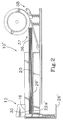
- Fig. 1 is a simplified fragmentary side elevation showing in cross section the printer paper pullout apparatus made in accordance with the preferred embodiment of the invention.
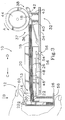
- Apparatus 10' does not include securing mechanism 14 or second spring element 28 of apparatus 10 of Fig. 1. Due to the inclusion of fewer parts, the manufacturing cost and physical wear of apparatus 10' is less than that of apparatus 10. However, paper tray 26' of apparatus 10' can be extended from feed zone 37 without fully depressing first expanse 16. Thus, the gripping force at operator end 30 may be less than the frictional forces on the paper stack from a guide rail (undepicted) or from the paper picking mechanisms 38 at feed end 36. This can result in top sheet 18 being left in the printer feed zone 37 upon extension of paper tray 26'.
- Grasping mechanism 12 is operable in common with capture mechanism 13.
- grasping mechanism 12 is also operable in common with tray release mechanism 14.
- operable in common with we mean that the operator need only use one hand to grip a paper stack 20 in a paper tray 26, release the paper tray 26 from the printer housing 34, and then extend the paper tray 26 and the paper stack 20 concurrently from the feed zone 37.
Landscapes
- Engineering & Computer Science (AREA)
- Mechanical Engineering (AREA)
- Sheets, Magazines, And Separation Thereof (AREA)
Claims (10)
- Dans un plateau (26) d'alimentation en papier d'imprimante destiné à supporter une pile (20) de papier dont des feuilles doivent être prélevées pour être imprimées, le plateau (26) étant au moins partiellement amovible de l'imprimante (32) pour manipuler la pile de papier, ledit plateau d'alimentation étant caractérisé par:
un mécanisme de préhension (12) actionnable et libérable à la main connecté au plateau (26), le mécanisme (12) permettant un effet manuel pour faciliter une extension du plateau (26) à partir de l'imprimante (32), ledit mécanisme de préhension (12) incluant un mécanisme de saisie (13) de la pile de papier actionnable en commun avec ledit mécanisme de préhension (12) pour fixer la pile de papier (12) dans le plateau (26) lors de l'enlèvement de ce dernier. - Le plateau d'alimentation selon la revendication 1, dans lequel le plateau (26) est fixé à l'intérieur de l'imprimante (32) dans une position prédéfinie (37) d'alimentation de feuilles de papier, dans lequel ledit mécanisme de préhension (12) inclut en outre un mécanisme de libération (14) de plateau, actionnable lui aussi en commun avec ledit mécanisme de préhension (12) pour libérer le plateau pour un tel enlèvement.
- Le plateau d'alimentation selon la revendication 1, dans lequel ledit mécanisme de saisie (13) inclut deux surfaces planes opposées (16, 22) ou davantage, une surface plane (16) étant positionnée généralement au-dessus de la pile (20) de papier et une surface plane (22) étant positionnée généralement en-dessous de cette pile, lesdits surface planes étant positionnées normalement de manière à permettre à une feuille de la pile (20) de papier d'être prélevée pour être imprimée, au moins l'une (16) desdites surfaces planes étant mobile par rapport à l'autre (22) lors de l'actionnement dudit mécanisme de préhension (12) de façon que la pile (20) de papier soit saisie par pincement entre lesdites surfaces planes (16, 22).
- Le plateau d'alimentation selon la revendication 3 dans lequel le plateau (26) est fixé de façon libérable dans une zone prédéfinie (37) d'alimentation de papier de l'imprimante (32), ledit mécanisme de préhension (12) incluant en outre un mécanisme de libération (14) de plateau, actionnable lui aussi en commun avec ledit mécanisme de préhension (12) pour libérer le plateau pour un tel enlèvement.
- Le plateau d'alimentation selon la revendication 4 dans lequel ledit mécanisme de libération (14) de plateau inclut un organe mobile (48) incluant un crochet (54) destiné à venir en prise de façon libérable avec le boitier (34) de l'imprimante de manière à fixer le plateau (26) dans ladite zone prédéfinie (37) d'alimentation, ledit organe (48) étant pivoté vers sa position de libération du plateau par l'actionnement dudit mécanisme de préhension (12) de pile de papier.
- Le plateau d'alimentation selon la revendication 5, dans lequel ladite surface plane (16) est sollicitée de manière à ramener automatiquement la surface plane (16) vers ladite position normale et dans lequel ledit organe mobile (48) est sollicité de manière à revenir automatiquement en prise avec le boitier (34) lors de la libération manuelle dudit mécanisme de préhension (12).
- Le plateau d'alimentation selon la revendication 6, dans lequel ladite surface plane (16) et ledit organe mobile (48) sont sollicités par un élément élastique (24) ou davantage.
- Appareil d'extraction (10) de pile de papier à utiliser dans une imprimante, l'appareil (10) comprenant un plateau (26) de papier destiné à alimenter, dans une imprimante (32), des feuilles d'une pile (20) de papier supportées par ce plateau, ledit appareil étant caractérisé en ce que ledit plateau (26) est extensible à partir de l'imprimante (32); et un mécanisme de serrage (12) est connecté audit plateau (26) et peut coopérer avec la pile (20) de papier supportée sur ledit plateau (26), ledit mécanisme (12) étant actionnable manuellement pour serrer la pile (20) de papier et pour faciliter l'extension, d'un seul tenant, dudit plateau (26) et de ladite pile (20) de papier qu'il supporte.
- L'appareil (10) selon la revendication 8, dans lequel le plateau (26) est fixé de façon libérable à l'intérieur de l'imprimante (32) dans une position prédéfinie (37) d'alimentation de papier, dans lequel ledit mécanisme de préhension (12) inclut en outre un mécanisme de libération (14) de plateau, actionnable lui aussi en commun avec ledit mécanisme de préhension (12) de manière à libérer le plateau (26) pour cette mise en extension.
- L'appareil (10) selon la revendication (8), dans lequel ledit mécanisme de serrage (12) de papier inclut deux surfaces planes opposées (16, 22) ou davantage, une surface plane (16) étant positionnée généralement au-dessus de la pile (20) de papier et une surface plane (22) étant positionnée généralement en-dessous de cette pile, lesdits surface planes étant positionnées normalement de manière à permettre à une feuille de la pile (20) de papier d'être prélevée pour être imprimée, l'une (16) desdites surfaces planes étant généralement mobile vers l'autre (22) lors de l'actionnement dudit mécanisme de préhension (12) de façon que la pile (20) de papier soit saisie par pincement entre lesdites surfaces planes (16, 22).
Applications Claiming Priority (2)
| Application Number | Priority Date | Filing Date | Title |
|---|---|---|---|
| US07/954,766 US5277418A (en) | 1992-09-29 | 1992-09-29 | Printer paper pullout apparatus |
| US954766 | 1992-09-29 |
Publications (2)
| Publication Number | Publication Date |
|---|---|
| EP0592116A1 EP0592116A1 (fr) | 1994-04-13 |
| EP0592116B1 true EP0592116B1 (fr) | 1996-11-13 |
Family
ID=25495900
Family Applications (1)
| Application Number | Title | Priority Date | Filing Date |
|---|---|---|---|
| EP93307215A Expired - Lifetime EP0592116B1 (fr) | 1992-09-29 | 1993-09-14 | Appareil pour extraire du papier d'imprimante |
Country Status (4)
| Country | Link |
|---|---|
| US (1) | US5277418A (fr) |
| EP (1) | EP0592116B1 (fr) |
| JP (1) | JP3357430B2 (fr) |
| DE (1) | DE69305960T2 (fr) |
Families Citing this family (12)
| Publication number | Priority date | Publication date | Assignee | Title |
|---|---|---|---|---|
| JP3371635B2 (ja) * | 1995-08-28 | 2003-01-27 | 富士通株式会社 | 媒体ホルダー並びに媒体搬送装置 |
| US6357740B1 (en) * | 1998-11-30 | 2002-03-19 | Canon Kabushiki Kaisha | Sheet feeding apparatus and image forming apparatus |
| KR100315638B1 (ko) * | 1999-06-24 | 2001-12-12 | 윤종용 | 전자사진 복합기 |
| US6254084B1 (en) * | 1999-08-19 | 2001-07-03 | Olympus America Inc. | Paper feed enhancer for printer feeder |
| JP4199405B2 (ja) * | 2000-03-17 | 2008-12-17 | 東芝テック株式会社 | 給紙装置 |
| US6550991B2 (en) | 2001-03-22 | 2003-04-22 | Electronics For Imaging, Inc. | Paper tray adjustment page |
| JP2003072970A (ja) * | 2001-09-03 | 2003-03-12 | Matsushita Electric Ind Co Ltd | 分離給紙装置 |
| US20080237976A1 (en) * | 2007-03-27 | 2008-10-02 | Niko Jay Murrell | Media Sheet Ramp For An Image Forming Device |
| KR101172395B1 (ko) * | 2007-07-05 | 2012-08-08 | 삼성전자주식회사 | 인쇄매체공급유닛 및 이를 포함하는 화상형성장치 |
| JP5721971B2 (ja) * | 2010-06-15 | 2015-05-20 | グンゼ株式会社 | シート給送装置 |
| JP5941892B2 (ja) * | 2013-10-28 | 2016-06-29 | 京セラドキュメントソリューションズ株式会社 | 給紙装置、およびこれを備えた画像形成装置 |
| JP6790765B2 (ja) * | 2016-11-30 | 2020-11-25 | コニカミノルタ株式会社 | 給紙装置及び給紙ユニット |
Family Cites Families (8)
| Publication number | Priority date | Publication date | Assignee | Title |
|---|---|---|---|---|
| JPS59190127A (ja) * | 1983-04-12 | 1984-10-27 | Olympus Optical Co Ltd | 給紙カセツト着脱装置 |
| JPS60244719A (ja) * | 1984-05-18 | 1985-12-04 | Matsushita Electric Ind Co Ltd | 給紙カセツト |
| JPS60244718A (ja) * | 1984-05-18 | 1985-12-04 | Fuji Xerox Co Ltd | 複写機用コピ−用紙収納容器 |
| US4915370A (en) * | 1987-03-02 | 1990-04-10 | Mita Industrial Co., Ltd. | Paper feeding device |
| DE3906983C2 (de) * | 1989-03-04 | 1995-12-21 | Kodak Ag | Vorratskassette für einen Blattstapel |
| JPH038634A (ja) * | 1989-06-02 | 1991-01-16 | Canon Inc | 給紙カセット |
| JPH038633A (ja) * | 1989-06-02 | 1991-01-16 | Canon Inc | 給紙カセット |
| DE4029039C2 (de) * | 1990-09-13 | 1995-06-01 | Kodak Ag | Vorratskassette für einen Blattstapel |
-
1992
- 1992-09-29 US US07/954,766 patent/US5277418A/en not_active Expired - Fee Related
-
1993
- 1993-09-14 EP EP93307215A patent/EP0592116B1/fr not_active Expired - Lifetime
- 1993-09-14 DE DE69305960T patent/DE69305960T2/de not_active Expired - Fee Related
- 1993-09-29 JP JP26576593A patent/JP3357430B2/ja not_active Expired - Fee Related
Also Published As
| Publication number | Publication date |
|---|---|
| JP3357430B2 (ja) | 2002-12-16 |
| DE69305960T2 (de) | 1997-03-13 |
| EP0592116A1 (fr) | 1994-04-13 |
| JPH06321363A (ja) | 1994-11-22 |
| US5277418A (en) | 1994-01-11 |
| DE69305960D1 (de) | 1996-12-19 |
Similar Documents
| Publication | Publication Date | Title |
|---|---|---|
| US5277418A (en) | Printer paper pullout apparatus | |
| EP0838419B1 (fr) | Dispositif de transport de feuilles | |
| JPH0524700A (ja) | シート給送装置及び画像形成装置 | |
| JPS6138088B2 (fr) | ||
| US5734404A (en) | Printer for feeding curled sheets | |
| EP0590822A1 (fr) | Appareil pour le traitement d'une pile de papier d'une imprimante | |
| US7591455B2 (en) | Sheet finishing apparatus | |
| US6209865B1 (en) | Method and apparatus for improved stacking quality in a device that effects one or more of media to an output storage location | |
| DE60215430T2 (de) | Aufzeichnungsvorrichtung | |
| WO2017099741A1 (fr) | Éjection d'une pile de feuilles de support | |
| US4717273A (en) | Multiple paper holder and method for a computer printer | |
| JPH08309967A (ja) | インクジェットプリンタにおける給排紙方法 | |
| JPH08208078A (ja) | 万能給紙装置 | |
| JPH05208744A (ja) | 給紙装置 | |
| US12186852B2 (en) | Method and apparatus for 3D printing using a stacker | |
| US11584080B1 (en) | Method and apparatus for 3D printing using a platen | |
| US11904549B2 (en) | Method and apparatus for 3D printing using a material feeder | |
| US2233472A (en) | Duplicating device | |
| JPH0732089Y2 (ja) | 背貼り装置に於けるテープ送り出し装置 | |
| JP2580689Y2 (ja) | 自動給紙装置 | |
| JP2006256729A (ja) | シート処理装置 | |
| JP3028837B2 (ja) | 用紙分配装置 | |
| JPH0732090Y2 (ja) | 背貼り装置に於ける冊子の案内ガイド | |
| JPH0730380Y2 (ja) | 背貼り装置 | |
| JP3028839B2 (ja) | 用紙分配装置 |
Legal Events
| Date | Code | Title | Description |
|---|---|---|---|
| PUAI | Public reference made under article 153(3) epc to a published international application that has entered the european phase |
Free format text: ORIGINAL CODE: 0009012 |
|
| AK | Designated contracting states |
Kind code of ref document: A1 Designated state(s): DE FR GB IT |
|
| 17P | Request for examination filed |
Effective date: 19940915 |
|
| GRAG | Despatch of communication of intention to grant |
Free format text: ORIGINAL CODE: EPIDOS AGRA |
|
| 17Q | First examination report despatched |
Effective date: 19960308 |
|
| GRAH | Despatch of communication of intention to grant a patent |
Free format text: ORIGINAL CODE: EPIDOS IGRA |
|
| GRAH | Despatch of communication of intention to grant a patent |
Free format text: ORIGINAL CODE: EPIDOS IGRA |
|
| GRAA | (expected) grant |
Free format text: ORIGINAL CODE: 0009210 |
|
| AK | Designated contracting states |
Kind code of ref document: B1 Designated state(s): DE FR GB IT |
|
| PG25 | Lapsed in a contracting state [announced via postgrant information from national office to epo] |
Ref country code: IT Free format text: LAPSE BECAUSE OF FAILURE TO SUBMIT A TRANSLATION OF THE DESCRIPTION OR TO PAY THE FEE WITHIN THE PRESCRIBED TIME-LIMIT;WARNING: LAPSES OF ITALIAN PATENTS WITH EFFECTIVE DATE BEFORE 2007 MAY HAVE OCCURRED AT ANY TIME BEFORE 2007. THE CORRECT EFFECTIVE DATE MAY BE DIFFERENT FROM THE ONE RECORDED. Effective date: 19961113 Ref country code: FR Effective date: 19961113 |
|
| REF | Corresponds to: |
Ref document number: 69305960 Country of ref document: DE Date of ref document: 19961219 |
|
| EN | Fr: translation not filed | ||
| PLBE | No opposition filed within time limit |
Free format text: ORIGINAL CODE: 0009261 |
|
| STAA | Information on the status of an ep patent application or granted ep patent |
Free format text: STATUS: NO OPPOSITION FILED WITHIN TIME LIMIT |
|
| 26N | No opposition filed | ||
| PGFP | Annual fee paid to national office [announced via postgrant information from national office to epo] |
Ref country code: GB Payment date: 19990820 Year of fee payment: 7 Ref country code: DE Payment date: 19990820 Year of fee payment: 7 |
|
| PG25 | Lapsed in a contracting state [announced via postgrant information from national office to epo] |
Ref country code: GB Free format text: LAPSE BECAUSE OF NON-PAYMENT OF DUE FEES Effective date: 20000914 |
|
| GBPC | Gb: european patent ceased through non-payment of renewal fee |
Effective date: 20000914 |
|
| PG25 | Lapsed in a contracting state [announced via postgrant information from national office to epo] |
Ref country code: DE Free format text: LAPSE BECAUSE OF NON-PAYMENT OF DUE FEES Effective date: 20010601 |