EP0592390B1 - Gâche - Google Patents
Gâche Download PDFInfo
- Publication number
- EP0592390B1 EP0592390B1 EP19930890197 EP93890197A EP0592390B1 EP 0592390 B1 EP0592390 B1 EP 0592390B1 EP 19930890197 EP19930890197 EP 19930890197 EP 93890197 A EP93890197 A EP 93890197A EP 0592390 B1 EP0592390 B1 EP 0592390B1
- Authority
- EP
- European Patent Office
- Prior art keywords
- threaded spindles
- closure piece
- threaded
- latch
- connection pieces
- Prior art date
- Legal status (The legal status is an assumption and is not a legal conclusion. Google has not performed a legal analysis and makes no representation as to the accuracy of the status listed.)
- Expired - Lifetime
Links
- 238000010304 firing Methods 0.000 claims 1
- 238000010276 construction Methods 0.000 description 2
- 238000007654 immersion Methods 0.000 description 1
Images
Classifications
-
- E—FIXED CONSTRUCTIONS
- E05—LOCKS; KEYS; WINDOW OR DOOR FITTINGS; SAFES
- E05B—LOCKS; ACCESSORIES THEREFOR; HANDCUFFS
- E05B15/00—Other details of locks; Parts for engagement by bolts of fastening devices
- E05B15/02—Striking-plates; Keepers; Bolt staples; Escutcheons
- E05B15/0205—Striking-plates, keepers, staples
- E05B15/024—Striking-plates, keepers, staples adjustable
- E05B15/025—Striking-plates, keepers, staples adjustable the striker being movable by a screw/nut
-
- E—FIXED CONSTRUCTIONS
- E05—LOCKS; KEYS; WINDOW OR DOOR FITTINGS; SAFES
- E05B—LOCKS; ACCESSORIES THEREFOR; HANDCUFFS
- E05B15/00—Other details of locks; Parts for engagement by bolts of fastening devices
- E05B15/02—Striking-plates; Keepers; Bolt staples; Escutcheons
- E05B15/0205—Striking-plates, keepers, staples
- E05B15/024—Striking-plates, keepers, staples adjustable
- E05B15/0245—Movable elements held by friction, cooperating teeth, or the like
Definitions
- the invention relates to a striker with an adjustable stop bar for adjusting the engagement position of a latch in the closed position of a wing, at least two threaded spindles are arranged with their axis of rotation in the closing direction in the striker, these threaded spindles in the striker or in the stop bar are axially immovable and the each other part has at least two threaded sections which engage the threaded spindles in a form-fitting manner, furthermore the threaded spindles can be rotated through an opening, in particular a bore opening on the wing side, for example by means of a screwdriver or a hexagon key, and preferably locking screws are provided on the striker, which Fix the position of the stop bar in the striker after adjustment using the threaded spindles.
- Such a striker is known from DE-A-35 02 989. It describes how an already installed door frame can be converted: The recess provided for the latch is first enlarged; Due to the enlarged recess, molded parts are then attached behind the frame. One molded part is screwed to the frame, the other is adjustable using adjusting screws. The adjusting screws are screwed into the molded part screwed to the frame and axially immovable in the adjustable molded part. The ends of the adjustable molded part are slotted in the axial direction of the adjusting screws; this means that the adjusting screws can be clamped securely by means of locking screws.
- the adjustable molded part must be made relatively thick so that it can withstand the forces that are transmitted to it from the trap.
- the door on the door frame rests over a fold on the outside; this means that the cutout in the striker for the latch is very close to the wing-side edge of the door frame, so that there is no more space for thick molded parts.
- the stop bar is part of a trap pocket with an approximately trough-shaped recess, which has a particularly inclined stop surface on the inside for engaging the trap side surface and at the longitudinal ends of the connectors for the threaded spindles are provided, the trap pocket with a the adjustment path through the threaded spindles corresponding play is slidably mounted in the striker.
- the threaded spindles cooperate with connectors which are provided at the two ends of the latch pocket - that is, above and below the recess for the latch. In this way, enough space for the threaded spindles and a sufficiently large adjustment path is possible.
- a special embodiment is characterized in that the connecting pieces on the wing side are engaged by the striker, that the connecting pieces have threaded bores into which the threaded spindles engage, and that the threaded spindles are axially immovably mounted in the rear engages for the connecting pieces.
- the connectors are so slightly offset from the door panel relative to the stop bar; the space gained in this way is filled with undercuts in which the threaded spindles are axially immovable.
- the threaded spindles engage in threaded bores provided in the connecting pieces. In each case, only approximately half-shell-shaped threaded parts can be provided as threaded bores, which form-fit only on one half of the threaded spindles concern without embracing them.
- elongated holes for locking screws are provided in parallel to the threaded holes for the threaded spindles in the stop bar, in particular in the connecting pieces on both sides, and the locking screws can be screwed into holes in the striker.
- the stop bar has the elongated holes here; the fixing screws are screwed into the striker behind the stop bar.
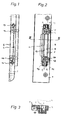
- Fig. 1 shows a striker in side view
- Fig. 2 in front view
- Fig. 3 shows a section along the line III-III in Fig. 2nd
- a striker 1 such as is milled into a door frame, comprises a stop bar 2, on the stop surface 3 of which a latch 4 abuts when the door leaf is closed.
- the stop bar 2 is part of a latch pocket 5 which is slidably mounted in a recess 6 of the striker 1. According to FIG. 2, the latch pocket 5 can be shifted to the left and right, whereby the stop bar 2 with its stop surface 3 creates a different suit or play for the latch 4.
- the threaded bores for threaded spindles 9, 10 are stationary, but rotatable, in recesses in the closing piece 1. They each have a hexagon socket 11, 12 on the end face. which can be reached through holes 13, 14 through a hex key.
- the latch pocket 5 and thus the stop bar 2 can thus be adjusted relative to the striker 1 via the threaded spindles 9, 10.
- the bores 13, 14 are covered when the door is closed or locked; this is an unauthorized adjustment prevented.
- locking screws 15, 16 are also provided, which extend through the elongated holes 17, 18 in the connecting pieces 7, 8 adjoining the latch pocket 5 and are screwed into the base body of the closing piece 1. Before an adjustment, these locking screws 15, 16 are loosened, then the adjustment is carried out by means of the threaded spindles 9, 10 and finally the locking screws 15, 16 can be tightened again.
- the bar 19 shown in FIG. 3 should also be mentioned, which limits the latch pocket 5 on the side opposite the stop bar 2. It serves to reinforce the entire displaceable component and has a lower height than the terminal strip 2, so that the inlet slope of the trap 4 does not hinder immersion in the trap pocket.
Landscapes
- Lock And Its Accessories (AREA)
- Closing And Opening Devices For Wings, And Checks For Wings (AREA)
Claims (3)
- Pièce de gâche (1) munie d'une barrette de butée réglable (2) pour le réglage de la position de contact d'un pêne (4) dans la position de fermeture d'un battant, dans laquelle au moins deux broches filetées (9, 10) sont disposées dans la pièce de gâche (1) avec leur axe de rotation dans la direction de fermeture, ces broches filetées (9, 10) étant montées dans la piéce de gâché (1) ou dans la barrette de tube (2) sans possibilité de déplacement axial et l'autre partie correspondante (2 ou 1) comportant au moins deux tronçons filetés, qui sont engagés en correspondante de forme (vissés) sur les broches filetées (9, 10), dans laquelle en outre les broches filetées (9, 10) sont susceptibles d'être entraînées en rotation à travers une ouverture, en particulier un alésage (13, 14) débouchant du côté du battant, par exemple à l'aide d'un tournevis ou d'une clé à six pans et dans laquelle sont de préférence prévues sur la pièce de gâche (1) des vis de fixation (15, 16), qui fixent la position de la barrette de butée (2) sur la pièce de gâche (1) après réglage par les broches filetées (9, 10), caractérisée en ce que la barrette de butée (2) est une partie d'une poche de pêne (5) munie d'une cavité sensiblement en forme d'auge, qui présente sur la face intérieure une surface d'appui, en particulier inclinée pour servir d'appui à la surface latérale du pêne et aux extrémités des faces latérales de laquelle sont prévues dcs pièces de liaison (7, 8) pour les broches filetées (9, 10), et en ce que la poche de pêne (5) est montée dans la pièce de gâche (1) en étant susceptible d'être déplacée par les broches filetées (9, 10) d'un jeu correspondant au déplacement de réglage.
- Pièce de gâche selon la revendication 1, caractérisée en ce que les pièces de liaison (7, 8) sont retenues, par un effet de contre-dépouille du côté du battant, par la pièce de gâche (1), en cc que les pièces de liaison (7, 8) comportent des alésages filetés, dans chacun desquels est vissée une broche filetée (9, 10), et en ce que les broches filetées (9, 10) sont montées sans possibilité de déplacement axial dans les cavités à effet de contre-dépouille pour les pièces de liaison (7, 8).
- Pièce de gâche selon la revendication 1 ou 2, caractérisée en ce que, parallèlement aux alésages filetés pour les broches filetées (9, 10), sont prévus dans la barrette de butée (2), en particulier dans les pièces de liaison des deux côtés (7, 8), des trous oblongs (17, 18) pour des vis de fixation (15, 16) et en ce que les vis de fixation (15, 16) sont susceptibles d'être vissées dans des alésages de la pièce de gâche (1).
Applications Claiming Priority (2)
| Application Number | Priority Date | Filing Date | Title |
|---|---|---|---|
| AT1996/92 | 1992-10-09 | ||
| AT199692A AT401403B (de) | 1992-10-09 | 1992-10-09 | Schliessstück |
Publications (2)
| Publication Number | Publication Date |
|---|---|
| EP0592390A1 EP0592390A1 (fr) | 1994-04-13 |
| EP0592390B1 true EP0592390B1 (fr) | 1996-04-24 |
Family
ID=3525587
Family Applications (1)
| Application Number | Title | Priority Date | Filing Date |
|---|---|---|---|
| EP19930890197 Expired - Lifetime EP0592390B1 (fr) | 1992-10-09 | 1993-10-08 | Gâche |
Country Status (3)
| Country | Link |
|---|---|
| EP (1) | EP0592390B1 (fr) |
| AT (1) | AT401403B (fr) |
| DE (1) | DE59302345D1 (fr) |
Families Citing this family (2)
| Publication number | Priority date | Publication date | Assignee | Title |
|---|---|---|---|---|
| DE29601885U1 (de) * | 1996-02-05 | 1997-06-05 | Niemann, Hans Dieter, 50169 Kerpen | Schließleiste |
| GB2425567B (en) * | 2005-04-29 | 2009-10-07 | Laird Security Hardware Ltd | Keeps for locking systems |
Family Cites Families (8)
| Publication number | Priority date | Publication date | Assignee | Title |
|---|---|---|---|---|
| DE7402626U (de) * | 1974-04-25 | Siegenia Frank Kg | Schließplatte für Treibstangenverschlüsse von Fenstern, Türen od. dgl | |
| GB543168A (en) * | 1940-12-23 | 1942-02-12 | Henry Hope & Sons Ltd | Improvements relating to door-fastening fittings for use on metal door frames |
| GB677953A (en) * | 1950-10-05 | 1952-08-27 | Stanmore Springs Ltd | Improvements in locks, latches and the like |
| US2884277A (en) * | 1956-04-20 | 1959-04-28 | Eileen N Hale | Latch plate mounting |
| CH599437A5 (en) * | 1975-10-06 | 1978-05-31 | Schliesstech Anst | Misalignment correcting lock bolt abutment |
| US4288120A (en) * | 1979-05-14 | 1981-09-08 | Moore Donald H | Door latch assembly |
| DE3502989A1 (de) * | 1984-11-13 | 1986-05-22 | Westdeutscher Rundfunk, Anstalt des öffentlichen Rechts, 5000 Köln | Justiervorrichtung fuer schallhemmende tueren |
| GB8907514D0 (en) * | 1989-04-04 | 1989-05-17 | Tonkin Roger G | An adjustable striking plate |
-
1992
- 1992-10-09 AT AT199692A patent/AT401403B/de not_active IP Right Cessation
-
1993
- 1993-10-08 DE DE59302345T patent/DE59302345D1/de not_active Expired - Fee Related
- 1993-10-08 EP EP19930890197 patent/EP0592390B1/fr not_active Expired - Lifetime
Also Published As
| Publication number | Publication date |
|---|---|
| EP0592390A1 (fr) | 1994-04-13 |
| AT401403B (de) | 1996-09-25 |
| DE59302345D1 (de) | 1996-05-30 |
| ATA199692A (de) | 1996-01-15 |
Similar Documents
| Publication | Publication Date | Title |
|---|---|---|
| DE2639065B2 (de) | Verriegelungsvorrichtung | |
| DE9317370U1 (de) | Schloß für eine schlüsselbetätigte Festsetzung der Treibstange des Beschlages eines Schiebe-Kipp-Fensters | |
| EP2752539B2 (fr) | Crémone espagnolette | |
| EP0856626B1 (fr) | Dispositif de fixation formant pince pour ferrures | |
| EP0592390B1 (fr) | Gâche | |
| EP2113624A2 (fr) | Dispositif de fixation de porte ou de fenêtre | |
| CH599437A5 (en) | Misalignment correcting lock bolt abutment | |
| DE102020206316B4 (de) | Antrieb | |
| DE19745553A1 (de) | Schließvorrichtung | |
| DE102007035123B4 (de) | Kippsicherung | |
| DE3543027A1 (de) | Doppelfluegelige brandschutztuer | |
| DE19603415C1 (de) | Vorrichtung zur Verriegelung eines zwischen zwei Endstellungen um eine Achse schwenkbaren, in Verschlußstellung befindlichen Bauteils zum Verschließen einer Zugangsöffnung zu einem von Wänden umschlossenen Raum | |
| EP0298292A2 (fr) | Serrure de porte à pêne et demi-tour coulissants | |
| DE29815095U1 (de) | Niveauschaltsperre | |
| DE19937889C1 (de) | Schaltschrank mit einem Schwenkrahmen | |
| DE19937891C1 (de) | Schaltschrank | |
| EP0143237B2 (fr) | Ferrure de poignée pour ferrures de tringles coulissantes de fenêtres, portes ou similaires | |
| DE8335786U1 (de) | Vorrichtung zum verriegeln von tueren oder fenstern | |
| EP0154124A2 (fr) | Serrure à pêne | |
| DE102019103075B3 (de) | Schaltschrank mit einem Rahmengestell und einem daran festgelegten Seitenwandelement | |
| DE29512995U1 (de) | Anschlagvorrichtung für Türen oder Tore | |
| DE2833652C2 (fr) | ||
| DE1653951A1 (de) | Mechanischer Verschluss an Glastueren | |
| DE2703967C2 (de) | An einem Pfosten aus einem Hohlprofil befestigbares Schließblech für Türen oder Tore | |
| EP0087542A1 (fr) | Fermeture de portes ou de fenêtres |
Legal Events
| Date | Code | Title | Description |
|---|---|---|---|
| PUAI | Public reference made under article 153(3) epc to a published international application that has entered the european phase |
Free format text: ORIGINAL CODE: 0009012 |
|
| AK | Designated contracting states |
Kind code of ref document: A1 Designated state(s): DE FR IT SE |
|
| 17P | Request for examination filed |
Effective date: 19940824 |
|
| 17Q | First examination report despatched |
Effective date: 19950804 |
|
| GRAH | Despatch of communication of intention to grant a patent |
Free format text: ORIGINAL CODE: EPIDOS IGRA |
|
| GRAA | (expected) grant |
Free format text: ORIGINAL CODE: 0009210 |
|
| AK | Designated contracting states |
Kind code of ref document: B1 Designated state(s): DE FR IT SE |
|
| REF | Corresponds to: |
Ref document number: 59302345 Country of ref document: DE Date of ref document: 19960530 |
|
| ET | Fr: translation filed | ||
| ITF | It: translation for a ep patent filed | ||
| PLBE | No opposition filed within time limit |
Free format text: ORIGINAL CODE: 0009261 |
|
| STAA | Information on the status of an ep patent application or granted ep patent |
Free format text: STATUS: NO OPPOSITION FILED WITHIN TIME LIMIT |
|
| 26N | No opposition filed | ||
| PGFP | Annual fee paid to national office [announced via postgrant information from national office to epo] |
Ref country code: SE Payment date: 20011008 Year of fee payment: 9 |
|
| PGFP | Annual fee paid to national office [announced via postgrant information from national office to epo] |
Ref country code: FR Payment date: 20011026 Year of fee payment: 9 |
|
| PGFP | Annual fee paid to national office [announced via postgrant information from national office to epo] |
Ref country code: DE Payment date: 20011121 Year of fee payment: 9 |
|
| PG25 | Lapsed in a contracting state [announced via postgrant information from national office to epo] |
Ref country code: SE Free format text: LAPSE BECAUSE OF NON-PAYMENT OF DUE FEES Effective date: 20021009 |
|
| PG25 | Lapsed in a contracting state [announced via postgrant information from national office to epo] |
Ref country code: DE Free format text: LAPSE BECAUSE OF NON-PAYMENT OF DUE FEES Effective date: 20030501 |
|
| EUG | Se: european patent has lapsed | ||
| PG25 | Lapsed in a contracting state [announced via postgrant information from national office to epo] |
Ref country code: FR Free format text: LAPSE BECAUSE OF NON-PAYMENT OF DUE FEES Effective date: 20030630 |
|
| REG | Reference to a national code |
Ref country code: FR Ref legal event code: ST |
|
| PG25 | Lapsed in a contracting state [announced via postgrant information from national office to epo] |
Ref country code: IT Free format text: LAPSE BECAUSE OF NON-PAYMENT OF DUE FEES Effective date: 20051008 |