EP0592769B1 - Verfahren für die Umsetzung von Bitkarten in einfarbige Daten - Google Patents
Verfahren für die Umsetzung von Bitkarten in einfarbige Daten Download PDFInfo
- Publication number
- EP0592769B1 EP0592769B1 EP93110127A EP93110127A EP0592769B1 EP 0592769 B1 EP0592769 B1 EP 0592769B1 EP 93110127 A EP93110127 A EP 93110127A EP 93110127 A EP93110127 A EP 93110127A EP 0592769 B1 EP0592769 B1 EP 0592769B1
- Authority
- EP
- European Patent Office
- Prior art keywords
- output
- bits
- source
- color data
- bit
- Prior art date
- Legal status (The legal status is an assumption and is not a legal conclusion. Google has not performed a legal analysis and makes no representation as to the accuracy of the status listed.)
- Expired - Lifetime
Links
Images


Classifications
-
- G—PHYSICS
- G06—COMPUTING OR CALCULATING; COUNTING
- G06K—GRAPHICAL DATA READING; PRESENTATION OF DATA; RECORD CARRIERS; HANDLING RECORD CARRIERS
- G06K15/00—Arrangements for producing a permanent visual presentation of the output data, e.g. computer output printers
-
- G—PHYSICS
- G06—COMPUTING OR CALCULATING; COUNTING
- G06K—GRAPHICAL DATA READING; PRESENTATION OF DATA; RECORD CARRIERS; HANDLING RECORD CARRIERS
- G06K15/00—Arrangements for producing a permanent visual presentation of the output data, e.g. computer output printers
- G06K15/02—Arrangements for producing a permanent visual presentation of the output data, e.g. computer output printers using printers
- G06K15/027—Test patterns and calibration
-
- H—ELECTRICITY
- H04—ELECTRIC COMMUNICATION TECHNIQUE
- H04N—PICTORIAL COMMUNICATION, e.g. TELEVISION
- H04N1/00—Scanning, transmission or reproduction of documents or the like, e.g. facsimile transmission; Details thereof
- H04N1/40—Picture signal circuits
- H04N1/40012—Conversion of colour to monochrome
-
- G—PHYSICS
- G06—COMPUTING OR CALCULATING; COUNTING
- G06K—GRAPHICAL DATA READING; PRESENTATION OF DATA; RECORD CARRIERS; HANDLING RECORD CARRIERS
- G06K2215/00—Arrangements for producing a permanent visual presentation of the output data
- G06K2215/0082—Architecture adapted for a particular function
-
- G—PHYSICS
- G06—COMPUTING OR CALCULATING; COUNTING
- G06K—GRAPHICAL DATA READING; PRESENTATION OF DATA; RECORD CARRIERS; HANDLING RECORD CARRIERS
- G06K2215/00—Arrangements for producing a permanent visual presentation of the output data
- G06K2215/0082—Architecture adapted for a particular function
- G06K2215/0094—Colour printing
Definitions
- This invention relates to a process for converting color bit map data to compressed monochrome data, and more particularly to convert color bit map data to resolution scaled monochrome data in Printer Control Language Method Two compressed data without explicit processing of all repeating source color data.
- the rasterized bit map for monochrome image at 300 dots per inch resolution requires approximately a megabyte of raster memory for each letter-size page. At 600 dots per inch, 3.8 megabytes of memory are required.
- Laser printers typically include an on board or internal memory capable of receiving rasterized data bit map information from a host processor. This bit map is used to construct page intermediate strips of rasterized data. The page intermediate strips of rasterized data are delivered to the laser print engine which operates at a constant speed. If new rasterized data is not available at a rate that keeps up with the engine's operation, a print "overrun" occurs and the page is not printable. To prevent this from occurring, page intermediate formatting must occur at a high enough rate to keep up with the print engine. This can only be accomplished if the host processor is sending formatted data at a high enough rate of speed, or the printer contains sufficient internal memory to hold the entire destination image bit map which has been delivered to it at perhaps a slower rate of speed from the host processor.
- PCL Printer Control Language
- PCL Method Two compression compares each byte of data to be sent, testing for whether it is "same” or “different” from a reference byte read. If it is "same", Method Two continues to read ahead in a rasterized row of data until the test indicates either "end of line” or "different”. From this information is constructed a two byte PCL compressed run, wherein the first byte indicates the number of times that the second byte is to be repeated in the rasterized row. In the event that the next byte read tests different from the previous byte read, then a literal run data string is constructed, wherein the first byte of the literal run indicates that the following bytes are to be printed in proper sequence. Method Two compression is an effective compression technique which is particularly useful for images which include numerous strings of repeated data.
- What is needed is a process which speeds up the conversion process by eliminating the need to convert each individual pixel's color data information to a gray scale value where there are strings of repeating color data. Also, to increase the speed of execution time, what is needed is a process by which the requirement to dither the scaled output pixels derived from the conversion of repeating source pixels is eliminated, particularly when upscaling to a higher resolution image than the original source image.
- a peripheral unit is used to convert color source image data to a rasterized, Printer Control Language Method Two compressed, monochrome bit map and includes a random access memory, a processor and a control memory that holds a plurality of procedures necessary to convert the color source code image to the rasterized, Printer Control Language Method Two compressed, monochrome bit map, including a storage memory containing a gray scale conversion table, dithering matrices, procedures for determining destination image dither tiling locations, scaling conversion calculations, PCL Method Two conversion code, and sub routines for establishing two arrays, a gray scale value array, and a bit mask array, each containing a number of elements equal to the dither pattern width of the output image dither tiles.
- the peripheral unit is used in conjunction with a three part conversion process, including an initial conversion cycle, a read-ahead cycle, and a compressed data dithering cycle.
- the process begins with the initial conversion cycle, wherein color data information for source pixels are converted to gray scale values which are entered in elements of the gray scale value array. Appropriately scaled output position bits are then entered into corresponding bit mask elements. Conversion of source pixels and entry of output position bits into the same or additional bit mask array elements continues until a counter determines that there are sufficient output position bits to fill a dither pattern tile width or row within the output image. The first element of the bit mask array is then tested to determine whether it contains all of the output position bits, which if it does, it indicates that repeating color data is present.
- the read ahead cycle is initiated, wherein the unconverted color data information for additional source pixels is read and directly compared to the unconverted original color data for the already converted source pixels and continues until either the end of the source row is reached, or until source color data of different value is encountered.
- the read ahead cycle ends and the dithering cycle begins.
- the read ahead cycle is skipped if the first bit mask array element test indicates that not all output position bits are located within the first bit mask element, and the process proceeds directly with the dithering cycle.
- the dithering cycle begins with selection of the appropriate dithering matrix for the first element of the gray scale value array.
- the selected dithering matrix is rotated or repositioned so that the first bit in the dithering matrix corresponds in both its X and Y position, to the actual X and Y position within the destination image dithering tile for the first output position bit to be dithered.
- the entire first element of the bit mask array is ANDed to the rotated dither matrix to generate output bits.
- Each bit mask element corresponds in size to the output image dithering tile width and, for purposes of data compression is divisible, in the X axis, by eight so as to facilitate direct data compression.
- the dithering process calculates the number of scaled output bits in the repeating string, attempts to compress the dithered output signal from the ANDing of the first bit mask element to the dithering matrix to a single byte and, if successful, generates a PCL Method Two repeating run compressed data signal for transmission to an output buffer.
- a literal run PCL Method Two compressed data signal is generated and transmitted to the output buffer.
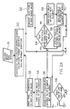
- Fig. 1 is a high level block diagram of a peripheral unit that is adapted to carry out the invention.
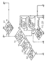
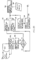
- Fig. 2 is a global flow diagram illustrating the overall procedure of the invention hereof.
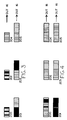
- Fig. 3 illustrates the conversion process employed in accordance with the procedures of Fig. 2.
- Fig. 4 illustrates the conversion process employed in accordance with the procedures of Fig. 2.
- peripheral unit 10 includes processor 12, input port 18, random access memory (RAM) 14, storage memory 16, output port 20, all connected by bus 22 and contains all of the procedures necessary to assure the conversion of color image data bit maps compressed monochrome bit maps for devices that use TIFF or pack bit data compression.
- the printer connected to output port 20 accepts Printer Control Language (PCL) Method Two compressed data format.
- PCL Printer Control Language
- Image data from the host processor is received via input port 18 and read into RAM 20.
- the image data may take one of several forms. It may include sub-images or pixels wherein the descriptors are contiguous with each sub-image and are processed along with each sub-image or wherein the sub-image or pixel descriptors are received separately from (but linked to) the actual sub-image data.
- peripheral unit 10 when peripheral unit 10 receives image data, it is parsed and commands and data are processed to derive raster graphics data that includes source image color data and location descriptors for each pixel of the source image.
- Storage memory 16 contains the sub routines that carry out the conversion procedure which include gray scale conversion table 28, dithering matrices 30, PCL Method Two conversion code 32, procedures for determining destination dither tiling locations 34, scaling conversion procedures 36 and two arrays, gray scale value array 24 and bit mask array 26.
- the two arrays, gray scale value array 24 and bit mask array 26, each contain a number of elements equal to-the dither pattern width of the output image dither tiles. Each are, in the preferred embodiment, evenly divisible by eight to facilitate PCL Method Two compression.
- the gray scale monochrome data is contained in a single eight bit byte, thus providing an availability of 254 shades of gray between pure white, represented by the binary number for 255, and solid black, represented by the binary number for 0.
- the source color data must be normalized during conversion to an appropriate monochrome gray shade, as for example the sixteen available colors in four bits per pixel color data format are spread across the spectrum of the 256 available shades of monochrome data.
- the bit mask array 26 is intended to hold information indicating the relative positions of the output pixels that will be generated for each associated gray value. Like the gray scale value array, it contains the number of elements equal to the dither pattern matrix width and, in the preferred embodiment is evenly divisible by eight for purposes of eventual data compression. Each element of the bit mask array contains a bit block of sufficient size to hold the number of output position bits equal to the dither pattern tile width of the output image, so that in the event all of the output pixels are of the same gray scale value, they can be contained within a single bit mask element.
- the elements of gray scale value array 24 and bit mask array 26 correspond to each other by their element indexes.
- the source color image is a video image with rasterized pixels at a resolution of seventy four per inch; the source color data for each pixel is contained in one eight bit byte which corresponds to 256 available colors including white and black; the dithering pattern matrices for the output image tiles are sixteen pixels by sixteen pixels; the device to which the output pixel data will be sent is a laser printer having a laser engine with a resolution of 600 dots per inch (DPI) and is compatible with Printer Control Language Method Two compression procedures; and finally, the source image, as is usually the case, contains a significant amount of repeating data.
- DPI dots per inch
- Fig. 2 a flow diagram, illustrates the actions taken in the peripheral unit to convert the pixels of the source color image to a PCL Method Two compressed data monochrome bit map.
- source image data is received through input port 18 and is converted to a raster graphic bit map, the source color data format is identified, and the scaling format to be used is calculated using scaling conversion procedures 36.
- the source format in this example is seventy four pixels per inch, and the output format or resolution is 600 DPI, which will result in scaling ratio of approximately 8.1 output pixels in both the horizontal, or X direction, and the vertical Y direction, for each input pixel, thus requiring the necessity of periodic rounded scaling so as to provide an output of 600 output pixels for each seventy four input pixels.
- the first byte of source color data information is converted to a monochrome gray scale value as determined from gray scale conversion table 28 as shown in Fig. 1, and as shown in Fig. 2 as box 52.
- This gray scale value is then entered, in the first element of the gray scale value array, as representationally shown in Fig. 3 as element 200 and as box 54 in Fig. 2.
- scaled output position bits which, in this example, for the first source pixel, would be eight output position bits, are entered, one at a time, in the first bit mask array element 201 of Fig.
- the color data byte for the next source pixel is retrieved and converted to its gray scale value as shown in box 62. It is then tested at decision box 64 to determine whether or not it is equal to the gray scale value of the first source pixel in box 54. If the test results indicate that the gray scale value is of a different value from that determined in box 52 and stored in box 54 for the first source pixel, then the second gray scale value is then entered into second element 202 of the gray scale value array as shown in Fig. 3 and as shown in box 68 of Fig. 2, and the appropriate number of scaled output position bits are entered into the corresponding second element 203 of bit mask array 26, as shown in Fig. 3, and box 70 of Fig. 2.
- the number of output position bits representing eventual output pixels are continuously counted in decision box 60 as they are entered into any element of bit mask array 26 until the appropriate number have been entered, which equals the width of the dither pattern tiles for the monochrome output image. If the scaling ratio were lower, for example four output position bits per source pixel, conversion of source pixels would continue until a full dither pattern tile width of output position bits had been generated, with each new gray scale value encountered being entered into a new gray scale value array element and scaled output position bits being entered into the corresponding element of the bit mask array. Also, as the color data for each source pixel is converted to a gray scale value, that value is tested in decision box 64 to determine whether that gray scale value has been encountered before in the current conversion cycle.
- the gray scale value is not re-entered into the next element of the gray scale value array, but instead the associated output position bits for the converted source pixel are entered into the proper relative locations within the bit mask element already associated with the previously encountered gray scale value as shown in box 66.
- the process of conversion of source color data into gray scale value stops. It stops even if the scaling process were to call for additional output position bits for the particular source pixel being converted. In the event scaling results in unused output position bits for the last source pixel converted, and no reading ahead occurs, this source pixel is reused, for the remaining scaled output position bits, as the first new source pixel converted when the conversion process begins anew in the conversion cycle.
- each source pixel were of a different color, and converted to a different gray scale
- sixteen elements would be needed in both gray scale value array 24 and bit mask array 26. For this reason, each array contains a sufficient number of elements to match the output dither pattern tile width. However, it is unlikely that all elements would be used in any given conversion and fill of the arrays.
- each bit mask element has a bit block large enough to hold a full dither pattern tile width, since it is much more likely that only one or two gray scale values will be encountered in any given conversion cycle.
- the first bit mask element 201 is tested to see if all of its sixteen bits are on, as shown in decision box 72 of Fig. 2. If they were all on, which in this first example of the conversion cycle they are not, it would indicate that the first two source pixels examined in this example were of the same color. Since not all bits in element 201 are on, the conversion process proceeds to dithering of the output position bits for eventual transmission to the output buffer of a PCL Method Two compressed data literal run entry.
- the X position, or the bit offset within the destination bit map dithering tile for the first output position bit to be dithered is calculated and the selected Y row of the dithering pattern matrix is rotated, in box 80, to match the X position of the first output position bit from dithering matrix to the X position of the first output bit in the destination dithering tile.
- bit mask element 201 is ANDed to the rotated dither pattern matrix row to generate what eventually will become output pixels.
- Bit mask element 201 is then ORed into a test flag to determine whether all sixteen output position bits are on as shown in decision box 84. If not, the process is repeated for the next gray scale array element 202 for the next gray scale value and associated output position bits.
- the next step is an attempt to compress the output data. This is accomplished, as shown in box 88 by grouping the sixteen output pixels into output bytes, and comparing the bytes to each other to determine if they are of the same value as shown in decision box 90. In this particular instance the output bytes will be of differing values since they were derived from different dithering pattern matrices.
- box 94 a literal run PCL Method Two compressed data string is constructed which is sent to the output buffer where it will be used in the construction of a complete PCL Method Two raster row command as shown in box 96. Once the complete command has been constructed it is sent to the printer through output port 98. Since there are no remaining output pixels, no remainder from box 122 is sent to the first bit mask element 201, box 56 in Fig. 2, and all the elements of both the gray scale value array 24 and the bit mask array 26 are reset to zero.
- the color data for two source pixels was converted which resulted in two elements of the bit mask array being used to construct a complete sixteen bit output position map.
- the next source pixel the third one
- the conversion of source data into gray scale data cycle begins anew as shown in Fig. 4, with the next source pixel (namely the third pixel) becoming the first source pixel, which in box 52 of Fig. 2 is converted to a gray scale value, and in box 54 is entered into element 200 of gray scale value array 24 as shown in Fig. 4.
- scaled output position bits are entered into bit mask element 201.
- the count in decision box 60 having determined that a full dither pattern width of output position bits are present initiates a test, as shown in decision box 72, to determine whether all of the bits in the first bit mask element are on. If so, all of the eventual output bits will of the same gray scale.
- the check procedure starts in decision box 100 with a determination of whether a single byte of source color data contains color information for more than one source pixel. If it does not, a 'No' decision in box 100, or if the source color information for each source pixel is contained in more than one byte, also a 'No' decision in box 100, then the byte values of the unconverted source color data for the next source pixels in the source row can be compared to the unconverted source color data for the last converted source pixel to determine if they are the same. If they are the same value, then the source pixels are the same color. The color data is compared byte for byte if the color data format is a single byte, or in the case of three byte or other multiple byte color data formats, then all multiple bytes are compared.
- each source byte of color data contains color information for more than one source pixel. If this occurs, a second test is made in decision box 102 to determine whether all pixels within the byte are the same color. This is done by comparing the color data values for each source pixel within the byte. If they are the same value, then the source pixels are the same color. If the decision is 'Yes', they are of the same color, then the process can proceed with a source byte comparison the same as in the case where this data is contained in one source byte.
- the source pixels are of different color and conversion to gray scale value and dithering proceeds as previously set forth in box 74.
- the source address and the source color value of the last source pixel converted are saved in save boxes 106 and 104 as shown in Fig. 2. Once saved, the process reads ahead in the source pixel row, testing each new source pixel color data value in decision box 108 to determine if it is the same as the saved source color value in save box 104. If it is the same, the address of the source pixel tested in decision box 108 is saved in save box 110, which is continuously updated with the address of the last source pixel which tested 'same' in decision box 108. This process continues until the end of the source image row is reached as determined in decision box 112 or until a source pixel tests 'different' in decision box 108.
- decision box 108 indicates 'different' source color values or end of line is reached in decision box 112
- a test is made in decision box 114 to determine whether the address of the last converted source pixel saved in save box 106 is the same as the address of the source pixel for which the color data was last tested and saved in save box 110. If they are the same then there was no reading ahead in the source image row. If they are different then the process has read ahead in the source image row without conversion and dithering of each source pixel that is the same color as the source pixels originally converted in this cycle of operation.
- the process calculates the number of source pixels from the beginning of the source image row to the address of the last saved source pixel in box 110 so as to determine the total number of scaled output pixels that need to be generated in the scaling process from the beginning of the output image row to the same relative position in the destination image as shown in box 118. From this total, in box 120, the total number of output pixels generated from skipping ahead can be computed by subtracting the number of output pixels already sent to the output buffer.
- the dither pattern width of output position bits will be dithered seriatim and any carry over of additional scaled output bits from the last read source pixel will be reentered in the next conversion cycle as the first source pixel gray scale value and output position bits. If the test result in decision box 72 is 'yes', these same leftover output position bits are accounted for in the calculation of the total number of output bits needed to reach the same relative position in the output image as computed in box 118.
- the gray scale value from gray scale value array element 200 is selected in box 74 and it, and the Y position in the output image dither pattern tile, are used to select the correct row of the correct dither pattern matrix as shown in box 76 in the same manner as in the dithering process for output pixels generated from first bit mask array element 201 in a cycle wherein there was no reading ahead.
- the selected dither pattern row is rotated in box 80 so that the first dither matrix bit in the Y row corresponds to the same X position for the first output, position bit in bit mask element 201 as it will be printed in the dither tile of the output image.
- Bit mask element 201 is then ANDed in box 82 to the rotated row of the dither pattern matrix to generate actual output pixels and Ored to insure that a complete dither pattern tile width has been generated.
- the calculation of the number of output bytes is performed in box 86 by dividing the number of output bits from box 120, plus the dither pattern width from bit mask array element 201, by eight. Because of the reading ahead and scaling which has occurred, the number of eventual output bytes may be substantial and there will likely be a remainder of output bits insufficient to create a final full byte. This remainder is saved in save box 122, along with the gray scale value in box 54 for inclusion in the next cycle of conversion unless the end of the row has been reached, in which case a final partial output byte will be constructed.
- the first complete dither pattern width of output bits has been divided into two repeating bytes of output data. It is also known, at this point, how many repeating bytes are required in the output string of data generated in this cycle.
- the dither pattern matrices that are used with the present invention are empirically determined, and wherever possible, each row of the matrix has a symmetrical pattern such that even if the row is rotated, when it is divided into output bytes, the bytes may likely be of equal value, such that the output can be constructed into repeating pairs of output bytes, or preferably into a repeating run PCL Method 2 compressed string entry as shown in box 92.
- the data string is constructed in box 92 or 94, it is sent to output buffer 96 where a complete PCL Method 2 command for a destination image raster row is constructed for eventual transmission through output port 98 to the printer or other device.
- a command is sent to zero out the gray scale and bit mask arrays.
- the gray scale value for the remainder bits in save box 122 will be the same as that found in box 54, element 200, and therefore this element is not reset to zero. Instead, the remainder bits are reentered as the first output position bit entries in bit mask element 201 as shown in box 56.
Landscapes
- Engineering & Computer Science (AREA)
- General Engineering & Computer Science (AREA)
- Physics & Mathematics (AREA)
- General Physics & Mathematics (AREA)
- Theoretical Computer Science (AREA)
- Multimedia (AREA)
- Signal Processing (AREA)
- Image Processing (AREA)
- Color Image Communication Systems (AREA)
- Facsimile Image Signal Circuits (AREA)
Claims (9)
- Verfahren zum Umwandeln von Quellenfarbbilddaten in Reihen einer rasterisierten Monochrom-Bittabelle in einer Peripherieeinheit, die Quellenpixelfarbbilddaten in Reihen einer rasterisierten Monochrom-Bittabelle umwandelt, wobei die Peripherieeinheit einen Speicher mit wahlfreiem Zugriff, einen Prozessor, einen Ausgangspuffer und einen Steuerspeicher aufweist, der eine Graustufenwertumwandlungstabelle, eine Mehrzahl von Zitterverfahrensmatrizen, Prozeduren zum Bestimmen der Position eines Ausgangspixels in einem Ausgangsbildzitterfeld für die rasterisierte Monochrom-Bittabelle, Skalierungsumwandlungsprozeduren zum Erzeugen von faktorisierten skalierten Ausgangspositionsbits sowohl in einer X- als auch einer Y-Richtung und Datenkomprimierungsprozeduren enthält, wobei das Verfahren folgende Schritte aufweist:
- a.
- Einrichten eines Arrays aus Elementen in dem Speicher mit wahlfreiem Zugriff zum Speichern von Graustufenwerten;
- b.
- Einrichten eines Arrays aus Bitmaskenelementen in dem Speicher mit wahlfreiem Zugriff, wobei jedes einen Bitblock zum Speichern von Ausgangspositionsbits aufweist, jedes Element mit einem entsprechenden Graustufenwertelement indexiert ist und jedes Element dimensioniert ist, um eine Mehrzahl von Ausgangspositionsbits zu halten, die mit der Anzahl der Bits in einer Reihe eines Ausgangsbildzittermusterfeldes übereinstimmt;
- c.
- Umwandeln der Farbdateninformationen eines Quellenpixels in einen entsprechenden Graustufenwert;
- d.
- Erzeugen einer einzigen Reihe aus skalierten Ausgangspositionsbits für das umgewandelte Quellenpixel;
- e.
- Speichern jedes unterschiedlichen Graustufenwertes, der aus einer Umwandlung der Farbdateninformationen erhalten wurde, in einem separaten Element des Graustufenwertarrays;
- f.
- Speichern der Ausgangspositionsbits in dem Bitmaskenarrayelement, das mit dem Graustufenarrayelement für das Quellenpixel indexiert ist, aus welchem Ausgangspositionsbits erzeugt wurden, wobei die Ausgangspositionsbits in dem Bitmaskenelement in derselben relativen Position bezüglich der anderen Ausgangspositionsbits wie die relative Position des Quellenpixels bezüglich der anderen umgewandelten Quellenpixel gespeichert werden;
- g.
- nacheinander Wiederholen der Schritte (c) bis (f), bis eine ausreichende Anzahl von Quellenpixeln umgewandelt worden ist, um eine Mehrzahl von Ausgangspositionsbits zu erzeugen, die gleich der Anzahl der Bits in einer Reihe eines Ausgangsbildzittermusterfeldes ist;
- h.
- Überprüfen, um zu bestimmen, ob alle der Ausgangspositionsbits in einem Bitmaskenelement gespeichert sind;
- i.
- falls die Überprüfung ergibt, daß alle Ausgangspositionsbits in einem Bitmaskenelement gespeichert sind, nacheinander Vergleichen der nicht umgewandelten Quellenpixelfarbdateninformationen für das nächste Quellenpixel mit den nicht umgewandelten Farbdateninformationen für das letzte umgewandelte Quellenpixel, entweder bis das Ende der Quellenreihe angetroffen wird oder bis Farbdateninformationen mit einem ungleichen Wert angetroffen werden;
- j.
- Speichern der Adresse des letzten Quellenpixels, das Farbdateninformationen mit demselben Wert wie die Farbdateninformationen des letzten umgewandelten Quellenpixels aufweist;
- k.
- Berechnen der Anzahl der Ausgangspositionsbits, die aus den überprüften und gezählten Quellenpixel mit demselben Wert von Farbdateninformationen erzeugt werden würden;
- l.
- Durchführen eines Zitterverfahrens mit den gespeicherten Ausgangspositionsbits, die in dem Bitmaskenelement gespeichert sind, um Ausgangsdatenbits zu erzeugen;
- m.
- Komprimieren der Ausgangsdatenbits und der berechneten Anzahl der Ausgangspositionsbits aus Schritt (k) in ein komprimiertes Datenausgangssignal;
- n.
- falls das Überprüfungsergebnis ergibt, daß die Ausgangspositionsbits in mehr als einem Bitmaskenelement gespeichert sind, Durchführen eines sequentiellen Zitterverfahrens mit den gespeicherten Ausgangspositionsbits in jedem Element des Bitmaskenarrays, das gespeicherte Ausgangspositionsbits hält, um nicht-zusammengesetzte Ausgangsdatenbits zu erzeugen;
- o.
- Zusammensetzen eines Ausgangssignals aus den nicht-zusammengesetzten Ausgangsdatenbits, um ein Ausgangssignal zu bilden;
- p.
- Senden des Ausgangssignals zu dem Ausgangspuffer;
- q.
- Speichern der Ausgangssignale in dem Ausgangspuffer;
- r.
- Zusammensetzen einer Reihe einer rasterisierten Monochrom-Bittabelle aus den Ausgangssignalen, die in dem Ausgangspuffer gespeichert sind, in dem Ausgangspuffer; und
- s.
- Wiederholen der Schritte (c) bis (r) für die in den Schritten (c) bis (g) umgewandelten Quellenpixel, um eine Anzahl von zusätzlichen Reihen einer rasterisierten Monochrom-Bittabelle zu erzeugen, die gleich dem Y-Skalierungsfaktor ist.
- Das Verfahren gemäß Anspruch 1, bei dem die Anzahl der Bits in dem Bitblock jedes Bitmaskenelements genau durch acht teilbar ist.
- Das Verfahren gemäß Anspruch 1, bei dem der Schritt (q) ferner das Zählen der Anzahl der Ausgangssignalbits für jede rasterisierte Monochrom-Bittabellenreihe aufweist, die in dem Ausgangspuffer gespeichert ist.
- Das Verfahren gemäß Anspruch 3, bei dem der Schritt (k) ferner folgende Schritte aufweist:
- k(1)
- Berechnen der Anzahl der Quellenpixel von dem Anfang der Quellenreihe bis zu dem letzten verglichenen Quellenpixel, das bzgl. des letzten konvertierten Quellenpixels Farbdateninformationen mit gleichem Wert aufweist;
- k(2)
- Berechnen der Anzahl der zu erzeugenden skalierten Ausgangspositionsbits von dem Anfang der Monochrom-Bittabellenreihe für die in Schritt k(1) berechnete Anzahl von Quellenpixeln;
- k(3)
- Subtrahieren der Anzahl der Ausgangssignale für die in dem Ausgangspuffer gespeicherte Reihe von der in Schritt k(2) berechneten Anzahl.
- Das Verfahren gemäß Anspruch 1, bei dem der Schritt (1) ferner folgende Schritte aufweist:
- l(1)
- Berechnen der Y-Position in dem Zittermusterfeld für das Ausgangspositionsbit in der ersten Position in dem gefüllten Bitmaskenelement;
- l(2)
- Berechnen der X-Position in dem Zittermusterfeld für das Ausgangspositionsbit in der ersten Position in dem gefüllten Bitmaskenelement;
- l(3)
- unter Verwendung des Graustufenwertes, der in dem Element gespeichert ist, das dem Element des Bitmaskenarrays entspricht, das mit Ausgangspositionsbits gefüllt ist, Auswählen einer Zittermustermatrix;
- l(4)
- Drehen der Zittermustermatrix, um das Zittermustermatrixbit, das eine Position aufweist, die der in den Schritten 1(1) und 1(2) berechneten X- und Y-Position entspricht, in der ersten Position in der Zittermustermatrix neu zu positionieren;
- l(5)
- Durchführen einer UND-Operation mit den Ausgangspositionsbits des Bitmaskenelements und der gedrehten Zittermustermatrix, um die Ausgangsdatenbits zu erzeugen.
- Das Verfahren gemäß Anspruch 1, in dem der Schritt (m) ferner folgende Schritte aufweist:
- (m)(1)
- Berechnen der Anzahl von Ausgangsbytes, indem die in Schritt (k) berechnete Anzahl der Ausgangspositionsbits durch acht dividiert wird;
- (m)(2)
- Gruppieren der Ausgangspositionsbits in Bytes aus jeweils acht Bit;
- (m)(3)
- Speichern der restlichen Ausgangspositionsbits;
- (m)(4)
- Gruppieren der Ausgangsdatenbits von Schritt (1) in Ausgangssignalbytes;
- (m)(5)
- Vergleichen der Ausgangssignalbytes, die in Schritt (m)(4) erzeugt wurden, um zu bestimmen, ob dieselben übereinstimmen oder sich unterscheiden;
- (m) (6)
- falls der in Schritt (m) (5) durchgeführte Vergleich ergibt, daß sich die Ausgangssignalbytes unterscheiden, Aufbauen eines Literallaufes der Ausgangssignalbytes unter Verwendung der in Schritt (m)(4) erzeugten Ausgangssignalbytes und der Anzahl der Ausgangsbytes, die in Schritt (m)(1) bestimmt wurde;
- (m) (7)
- falls der in Schritt (m)(5) durchgeführte Vergleich ergibt, daß die Ausgangssignalbytes übereinstimmen, Aufbauen eines komprimierten Wiederhol-Lauf-Datenausgangssignals;
- (m)(8)
- Neuschreiben des ersten Elements des Bitmaskenarrays, um eine Anzahl von Ausgangspositionsbits aufzunehmen, die gleich dem Rest der Ausgangspositionsbits ist, der in Schritt (m) (3) bestimmt wurde.
- Das Verfahren gemäß Anspruch 1, bei dem der Schritt (n) ferner folgende Schritte aufweist:
- n(1)
- Berechnen der Y-Position in dem Zittermusterfeld für das erste Ausgangspositionsbit in dem ersten Bitmaskenelement;
- n(2)
- Berechnen der X-Position in dem Zittermusterfeld für das erste Ausgangspositionsbit in dem ersten Bitmaskenelement;
- n(3)
- Unter Verwendung des Graustufenwertes, der in dem Element des Graustufenwertarrays gespeichert ist, das dem ersten Bitmaskenelement entspricht, Auswählen einer Zittermustermatrix;
- n(4)
- Drehen der Zittermustermatrix, um das Zittermustermatrixbit, das eine Position aufweist, die der X- und Y-Position entspricht, die in den Schritten n(1) und n(2) berechnet wurde, in der ersten Position in der Zittermustermatrix neu zu positionieren;
- n(5)
- Durchführen einer UND-Operation mit den Ausgangspositionsbits des Bitmaskenelements und der gedrehten Zittermustermatrix, um die Ausgangsdatenbits zu erzeugen; und
- n(6)
- nacheinander Wiederholen der Schritte n(1) bis n(5), bis mit allen Ausgangspositionsbits, die in den Schritten (f) und (g) erzeugt und gespeichert wurden, eine UND-Operation mit einer Zittermustermatrix durchgeführt worden ist.
- Das Verfahren gemäß Anspruch 1, bei dem der Schritt (o) ferner folgende Schritte aufweist:
- o(1)
- Durchführen einer ODER-Operation mit den nicht-zusammengesetzten Ausgangsdatenbits, die in Schritt (n) erzeugt wurden, und einem Testarray, um eine Zusammensetzung der Ausgangsdatenbits zu erzeugen;
- o(2)
- Unterteilen der Zusammensetzung der Ausgangsdatenbits in Gruppen aus acht, um Ausgangssignalbytes zu bilden.
- Das Verfahren gemäß Anspruch 1, bei dem der Schritt (i) ferner folgende Schritte aufweist:
- (i)(1)
- Überprüfen, um zu bestimmen, ob ein Quellenbildfarbdatenbyte Farbinformationen für mehr als ein Quellenpixel enthält;
- (i)(2)
- falls die in Schritt (i)(1) durchgeführte Überprüfung ergibt, daß in jedem Quellenbildfarbdatenbyte für mehr als ein Quellenpixel Farbdaten vorhanden sind, Überprüfen der Farbdaten für jedes Quellenpixel, die in jedem Byte enthalten sind, um zu bestimmen, ob dieselben übereinstimmen;
- (i)(3)
- falls die in Schritt (i)(2) durchgeführte Überprüfung ergibt, daß die Farbdaten für jedes Quellenpixel, das in einem Quellenbildfarbdatenbyte enthalten ist, übereinstimmen, nacheinander Vergleichen der nicht-umgewandelten Bytes der nicht-umgewandelten Farbdateninformationen für die nächsten Quellenpixel mit dem nicht-umgewandelten Byte der Farbdateninformationen für die letzten umgewandelten Quellenpixel, bis entweder das Ende der Quellenreihe oder ein Byte der Farbdateninformationen mit einem ungleichen Wert angetroffen wird;
- (i)(4)
- falls die in Schritt (i)(2) durchgeführte Überprüfung ergibt, daß die Farbdaten für jedes Quellenpixel, die in einem Quellenbildfarbdatenbyte enthalten sind, unterschiedlich sind, Überspringen der Schritte (j) bis (m);
- (i)(5)
- falls die in Schritt (i)(1) durchgeführte Überprüfung ergibt, daß die Farbdaten für nicht mehr als ein Quellenpixel vorhanden sind, die in jedem Quellenbildfarbdatenbyte enthalten sind, nacheinander Vergleichen der nicht-umgewandelten Bytes der nicht-umgewandelten Farbdateninformationen für die nächsten Quellenpixel mit den nicht-umgewandelten Bytes der Farbdateninformationen für die letzten umgewandelten Quellenpixel, bis entweder das Ende der Quellenreihe angetroffen wird oder die Bytes der Farbdateninformationen mit einem ungleichen Wert angetroffen werden.
Applications Claiming Priority (2)
| Application Number | Priority Date | Filing Date | Title |
|---|---|---|---|
| US960761 | 1992-10-13 | ||
| US07/960,761 US5457772A (en) | 1992-10-13 | 1992-10-13 | Method to convert bitmaps to monochrome data |
Publications (2)
| Publication Number | Publication Date |
|---|---|
| EP0592769A1 EP0592769A1 (de) | 1994-04-20 |
| EP0592769B1 true EP0592769B1 (de) | 1998-07-29 |
Family
ID=25503586
Family Applications (1)
| Application Number | Title | Priority Date | Filing Date |
|---|---|---|---|
| EP93110127A Expired - Lifetime EP0592769B1 (de) | 1992-10-13 | 1993-06-24 | Verfahren für die Umsetzung von Bitkarten in einfarbige Daten |
Country Status (4)
| Country | Link |
|---|---|
| US (1) | US5457772A (de) |
| EP (1) | EP0592769B1 (de) |
| JP (1) | JP3406030B2 (de) |
| DE (1) | DE69319988T2 (de) |
Families Citing this family (19)
| Publication number | Priority date | Publication date | Assignee | Title |
|---|---|---|---|---|
| US5548689A (en) * | 1992-10-13 | 1996-08-20 | Hewlett-Packard Company | Method to convert bitmaps to monochrome data |
| JP3554034B2 (ja) * | 1994-09-02 | 2004-08-11 | キヤノン株式会社 | カラー印刷装置及びその方法 |
| DE19508163A1 (de) * | 1995-03-08 | 1996-09-12 | Hell Ag Linotype | Verfahren zur Vereinigung von Farbauszugswerten zu einer einem Farbdruck entsprechenden Schwarz/Weiß-Ausgabe |
| US5713019A (en) * | 1995-10-26 | 1998-01-27 | Keaten; Timothy M. | Iconic access to remote electronic monochrome raster data format document repository |
| US5619342A (en) * | 1995-11-30 | 1997-04-08 | Hewlett-Packard Company | Method for determinig a destination pixel location from an arbitrary source pixel location during scaling of a bit map image |
| US5754743A (en) * | 1996-04-10 | 1998-05-19 | Snap-On Technologies, Inc. | Apparatus and method for printing color screen displays on a monochrome printer |
| US6298164B1 (en) * | 1998-10-02 | 2001-10-02 | Canon Kabushiki Kaisha | PCL conversion of JETSEND images |
| US6567186B1 (en) * | 1998-10-27 | 2003-05-20 | Hewlett-Packard Company | Method for determining gray values in a printer |
| US6201614B1 (en) | 1998-12-24 | 2001-03-13 | Electronics For Imaging, Inc. | Dithered image compression system |
| KR20000074329A (ko) * | 1999-05-20 | 2000-12-15 | 윤종용 | 라인프린터에서 피씨엘4 이상의 에뮬레이션을 출력하는 방법 |
| EP1585310A1 (de) * | 2004-03-30 | 2005-10-12 | Dialog Semiconductor GmbH | Umwandlung der Bildauflösung |
| EP1583031A1 (de) | 2004-03-30 | 2005-10-05 | Dialog Semiconductor GmbH | Zoomalgorithmus |
| US7869094B2 (en) * | 2005-01-07 | 2011-01-11 | Mitcham Global Investments Ltd. | Selective dithering |
| US8115977B2 (en) * | 2005-09-08 | 2012-02-14 | Go Daddy Operating Company, LLC | Document color and shades of gray optimization using monochrome patterns |
| US7777917B2 (en) * | 2005-09-08 | 2010-08-17 | The Go Daddy Group, Inc. | Document color and shades of gray optimization using solid monochrome colors |
| US8179565B2 (en) * | 2005-09-08 | 2012-05-15 | Go Daddy Operating Company, LLC | Document color and shades of gray optimization using outlining |
| US7502135B2 (en) * | 2005-09-08 | 2009-03-10 | The Go Daddy Group, Inc. | Document color and shades of gray optimization using dithered monochrome surfaces |
| US9564099B2 (en) * | 2014-03-10 | 2017-02-07 | Lumotune Inc. | Bistable display systems and methods |
| CN114244968B (zh) * | 2021-12-20 | 2024-01-09 | 北京镁伽科技有限公司 | 图像转换方法、图像转换装置及图像信号发生器 |
Family Cites Families (9)
| Publication number | Priority date | Publication date | Assignee | Title |
|---|---|---|---|---|
| US4688031A (en) * | 1984-03-30 | 1987-08-18 | Wang Laboratories, Inc. | Monochromatic representation of color images |
| US4977398A (en) * | 1988-01-15 | 1990-12-11 | Chips And Technologies, Incorporated | Color to monochrome conversion |
| US5245327A (en) * | 1988-01-15 | 1993-09-14 | Chips And Technologies, Incorporated | Color to monochrome conversion |
| US5612792A (en) * | 1990-03-05 | 1997-03-18 | Canon Kabushiki Kaisha | Image processing method and apparatus for outputting a pattern image in accordance with the color and density level of each color of the output polychromatic image |
| JPH0490669A (ja) * | 1990-08-03 | 1992-03-24 | Canon Inc | 印刷装置 |
| US5153576A (en) * | 1990-08-29 | 1992-10-06 | Xerox Corporation | Mapping of color images to black-and-white textured images |
| JP2992320B2 (ja) * | 1990-09-18 | 1999-12-20 | 株式会社リコー | 画像形成装置 |
| US5323247A (en) * | 1990-12-04 | 1994-06-21 | Research Corporation Technologies | Method and apparatus for halftoning and inverse halftoning and the transmission of such images |
| JP2683164B2 (ja) * | 1991-03-09 | 1997-11-26 | 三田工業株式会社 | カラ−画像形成装置 |
-
1992
- 1992-10-13 US US07/960,761 patent/US5457772A/en not_active Expired - Lifetime
-
1993
- 1993-06-24 EP EP93110127A patent/EP0592769B1/de not_active Expired - Lifetime
- 1993-06-24 DE DE69319988T patent/DE69319988T2/de not_active Expired - Fee Related
- 1993-10-13 JP JP25566093A patent/JP3406030B2/ja not_active Expired - Fee Related
Also Published As
| Publication number | Publication date |
|---|---|
| DE69319988D1 (de) | 1998-09-03 |
| US5457772A (en) | 1995-10-10 |
| DE69319988T2 (de) | 1999-03-18 |
| JP3406030B2 (ja) | 2003-05-12 |
| EP0592769A1 (de) | 1994-04-20 |
| JPH06233146A (ja) | 1994-08-19 |
Similar Documents
| Publication | Publication Date | Title |
|---|---|---|
| EP0592769B1 (de) | Verfahren für die Umsetzung von Bitkarten in einfarbige Daten | |
| US4555802A (en) | Compaction and decompaction of non-coded information bearing signals | |
| US5602976A (en) | Method and apparatus for saving printer memory | |
| EP0298446B1 (de) | Datenverringerung für die Bildanzeige von Ganzseiten-Graphiken | |
| EP0887763B1 (de) | Verfahren und Vorrichtung zum Aufbau von Bitmap-Daten in einem Drucker | |
| US4937761A (en) | Method and apparatus for enhanced speed graphic image processing | |
| US5548689A (en) | Method to convert bitmaps to monochrome data | |
| GB2224187A (en) | Image data processor having means for changing resolution of output images | |
| EP0712095B1 (de) | Verfahren und Vorrichtung zur Bilddatenkompression | |
| US7031019B1 (en) | Printer control apparatus, printer and printing system | |
| US4953104A (en) | Page buffer for an electronic gray-scale color printer | |
| US5457776A (en) | Compact memory for mixed text in graphics | |
| US20020126312A1 (en) | Accelerating color conversion using a temporary palette cache | |
| US7333238B2 (en) | Rendering a printing device pixel map | |
| US20030234947A1 (en) | Method and apparatus for creating color conversion table | |
| EP0770301B1 (de) | Bilddatenkompressionsverfahren und -vorrichtung | |
| EP0482848B1 (de) | Bildaufzeichnungsgerät | |
| US7538905B2 (en) | Resolution doubling for printer apparatus | |
| JPH07306940A (ja) | カラー・ビットマップをモノクローム・データに変換する方法 | |
| US5758044A (en) | Method and apparatus for rendering using a band by band depth adjustment | |
| AU757819B2 (en) | Method and apparatus for data compression | |
| EP1659567B1 (de) | Verwaltung von Schriftartdaten | |
| JPH09186898A (ja) | 画像処理装置及びその方法 | |
| KR930009674B1 (ko) | 레이저 프린터의 도트 프린터 비트 이미지 에뮬레이션 방법 | |
| EP0392655A2 (de) | Bilderzeugungssystem und -Verfahren |
Legal Events
| Date | Code | Title | Description |
|---|---|---|---|
| PUAI | Public reference made under article 153(3) epc to a published international application that has entered the european phase |
Free format text: ORIGINAL CODE: 0009012 |
|
| AK | Designated contracting states |
Kind code of ref document: A1 Designated state(s): DE FR GB IT |
|
| 17P | Request for examination filed |
Effective date: 19940225 |
|
| GRAG | Despatch of communication of intention to grant |
Free format text: ORIGINAL CODE: EPIDOS AGRA |
|
| 17Q | First examination report despatched |
Effective date: 19970731 |
|
| GRAG | Despatch of communication of intention to grant |
Free format text: ORIGINAL CODE: EPIDOS AGRA |
|
| GRAG | Despatch of communication of intention to grant |
Free format text: ORIGINAL CODE: EPIDOS AGRA |
|
| GRAH | Despatch of communication of intention to grant a patent |
Free format text: ORIGINAL CODE: EPIDOS IGRA |
|
| GRAH | Despatch of communication of intention to grant a patent |
Free format text: ORIGINAL CODE: EPIDOS IGRA |
|
| GRAA | (expected) grant |
Free format text: ORIGINAL CODE: 0009210 |
|
| ITF | It: translation for a ep patent filed | ||
| AK | Designated contracting states |
Kind code of ref document: B1 Designated state(s): DE FR GB IT |
|
| REF | Corresponds to: |
Ref document number: 69319988 Country of ref document: DE Date of ref document: 19980903 |
|
| ET | Fr: translation filed | ||
| PLBE | No opposition filed within time limit |
Free format text: ORIGINAL CODE: 0009261 |
|
| STAA | Information on the status of an ep patent application or granted ep patent |
Free format text: STATUS: NO OPPOSITION FILED WITHIN TIME LIMIT |
|
| 26N | No opposition filed | ||
| REG | Reference to a national code |
Ref country code: GB Ref legal event code: 732E |
|
| REG | Reference to a national code |
Ref country code: FR Ref legal event code: TP |
|
| REG | Reference to a national code |
Ref country code: GB Ref legal event code: IF02 |
|
| PGFP | Annual fee paid to national office [announced via postgrant information from national office to epo] |
Ref country code: IT Payment date: 20060630 Year of fee payment: 14 |
|
| PGFP | Annual fee paid to national office [announced via postgrant information from national office to epo] |
Ref country code: DE Payment date: 20070731 Year of fee payment: 15 |
|
| PGFP | Annual fee paid to national office [announced via postgrant information from national office to epo] |
Ref country code: GB Payment date: 20070628 Year of fee payment: 15 |
|
| PGFP | Annual fee paid to national office [announced via postgrant information from national office to epo] |
Ref country code: FR Payment date: 20070618 Year of fee payment: 15 |
|
| GBPC | Gb: european patent ceased through non-payment of renewal fee |
Effective date: 20080624 |
|
| REG | Reference to a national code |
Ref country code: FR Ref legal event code: ST Effective date: 20090228 |
|
| PG25 | Lapsed in a contracting state [announced via postgrant information from national office to epo] |
Ref country code: DE Free format text: LAPSE BECAUSE OF NON-PAYMENT OF DUE FEES Effective date: 20090101 |
|
| PG25 | Lapsed in a contracting state [announced via postgrant information from national office to epo] |
Ref country code: GB Free format text: LAPSE BECAUSE OF NON-PAYMENT OF DUE FEES Effective date: 20080624 |
|
| PG25 | Lapsed in a contracting state [announced via postgrant information from national office to epo] |
Ref country code: FR Free format text: LAPSE BECAUSE OF NON-PAYMENT OF DUE FEES Effective date: 20080630 |
|
| PG25 | Lapsed in a contracting state [announced via postgrant information from national office to epo] |
Ref country code: IT Free format text: LAPSE BECAUSE OF NON-PAYMENT OF DUE FEES Effective date: 20070624 |