EP0592796A1 - Verfahren und Vorrichtung zur Ermittlung der Luftqualität - Google Patents
Verfahren und Vorrichtung zur Ermittlung der Luftqualität Download PDFInfo
- Publication number
- EP0592796A1 EP0592796A1 EP93113768A EP93113768A EP0592796A1 EP 0592796 A1 EP0592796 A1 EP 0592796A1 EP 93113768 A EP93113768 A EP 93113768A EP 93113768 A EP93113768 A EP 93113768A EP 0592796 A1 EP0592796 A1 EP 0592796A1
- Authority
- EP
- European Patent Office
- Prior art keywords
- air quality
- humidity
- temperature
- quality level
- sensing means
- Prior art date
- Legal status (The legal status is an assumption and is not a legal conclusion. Google has not performed a legal analysis and makes no representation as to the accuracy of the status listed.)
- Granted
Links
Images



Classifications
-
- F—MECHANICAL ENGINEERING; LIGHTING; HEATING; WEAPONS; BLASTING
- F24—HEATING; RANGES; VENTILATING
- F24F—AIR-CONDITIONING; AIR-HUMIDIFICATION; VENTILATION; USE OF AIR CURRENTS FOR SCREENING
- F24F11/00—Control or safety arrangements
-
- F—MECHANICAL ENGINEERING; LIGHTING; HEATING; WEAPONS; BLASTING
- F24—HEATING; RANGES; VENTILATING
- F24F—AIR-CONDITIONING; AIR-HUMIDIFICATION; VENTILATION; USE OF AIR CURRENTS FOR SCREENING
- F24F11/00—Control or safety arrangements
- F24F11/62—Control or safety arrangements characterised by the type of control or by internal processing, e.g. using fuzzy logic, adaptive control or estimation of values
- F24F11/63—Electronic processing
- F24F11/64—Electronic processing using pre-stored data
-
- F—MECHANICAL ENGINEERING; LIGHTING; HEATING; WEAPONS; BLASTING
- F24—HEATING; RANGES; VENTILATING
- F24F—AIR-CONDITIONING; AIR-HUMIDIFICATION; VENTILATION; USE OF AIR CURRENTS FOR SCREENING
- F24F11/00—Control or safety arrangements
- F24F11/30—Control or safety arrangements for purposes related to the operation of the system, e.g. for safety or monitoring
-
- F—MECHANICAL ENGINEERING; LIGHTING; HEATING; WEAPONS; BLASTING
- F24—HEATING; RANGES; VENTILATING
- F24F—AIR-CONDITIONING; AIR-HUMIDIFICATION; VENTILATION; USE OF AIR CURRENTS FOR SCREENING
- F24F2110/00—Control inputs relating to air properties
- F24F2110/10—Temperature
-
- F—MECHANICAL ENGINEERING; LIGHTING; HEATING; WEAPONS; BLASTING
- F24—HEATING; RANGES; VENTILATING
- F24F—AIR-CONDITIONING; AIR-HUMIDIFICATION; VENTILATION; USE OF AIR CURRENTS FOR SCREENING
- F24F2110/00—Control inputs relating to air properties
- F24F2110/20—Humidity
-
- F—MECHANICAL ENGINEERING; LIGHTING; HEATING; WEAPONS; BLASTING
- F24—HEATING; RANGES; VENTILATING
- F24F—AIR-CONDITIONING; AIR-HUMIDIFICATION; VENTILATION; USE OF AIR CURRENTS FOR SCREENING
- F24F2110/00—Control inputs relating to air properties
- F24F2110/50—Air quality properties
-
- Y—GENERAL TAGGING OF NEW TECHNOLOGICAL DEVELOPMENTS; GENERAL TAGGING OF CROSS-SECTIONAL TECHNOLOGIES SPANNING OVER SEVERAL SECTIONS OF THE IPC; TECHNICAL SUBJECTS COVERED BY FORMER USPC CROSS-REFERENCE ART COLLECTIONS [XRACs] AND DIGESTS
- Y02—TECHNOLOGIES OR APPLICATIONS FOR MITIGATION OR ADAPTATION AGAINST CLIMATE CHANGE
- Y02B—CLIMATE CHANGE MITIGATION TECHNOLOGIES RELATED TO BUILDINGS, e.g. HOUSING, HOUSE APPLIANCES OR RELATED END-USER APPLICATIONS
- Y02B30/00—Energy efficient heating, ventilation or air conditioning [HVAC]
- Y02B30/70—Efficient control or regulation technologies, e.g. for control of refrigerant flow, motor or heating
Definitions
- the present invention relates to a method and apparatus for determining an air quality by detecting an air quality in an accommodation space.
- an air quality determination apparatus used in a conventional air quality regulator merely determines air quality by reference to an initially predetermined condition, that is, a set value corresponding to plural temperature stages or humidity stages, thus, the air quality regulator operated on the basis of the determination result can provide an operation control only in accordance with the predetermined set value, and it was almost impossible to obtain a control in response to actual changes of air quality in an accommodation space.
- an air quality regulator is required to be operated in consideration of both temperature and humidity, because it may be felt uncomfortable, when only the humidity is changed, even if it is comfortable in certain conditions of temperature and humidity.
- the method for determining an air quality level of the present invention comprises : a step of predefining a formula used in obtaining an output value of air quality level sensing means according to conditions of temperature and humidity at clean state, a step of calculating an output value at clean state of the air quality level sensing means based on a temperature and humidity at air quality detection using the formula, a step of taking as a correction amount a difference between the calculated output value and an output value at clean state of the air quality level sensing means in conditions of temperature and humidity which provides an absolute determination reference of air quality level, a step of correcting a threshold value which is pre-determined in said conditions of temperature and humidity which provides an absolute determination reference , by adding the correction amount to the threshold value, and determining an air quality level by comparing an output of the air quality sensing means upon said temperature and humidity at air quality detection , with the corrected threshold value.
- an output value at clean state of air quality level sensing means based on a temperature and humidity at air quality detection is calculated from a predefined formula, and as a correction amount a difference between the calculated value and an output value at clean state of the air quality level sensing means in conditions of temperature and humidity which provides an absolute determination reference of air quality level , is calculated , and a threshold value which is determined under temperature and humidity of the absolute determination reference of air quality level is corrected by adding the correction amount to the threshold value, and an output upon air quality detection of the air quality sensing means and the corrected threshold value are compared.
- the apparatus for determining an air quality level of the present invention comprises; air quality sensing means for detecting a state of air quality, temperature and humidity sensing means for detecting temperature and humidity, reference value output means having preliminary relational information established between different temperatures and humidities and output values of the air quality sensing means in a reference air quality , computing means for obtaining a threshold value for air quality determination upon air quality detection by amending a predetermined threshold value of absolute determination reference of air quality level , referring to the relational information, on the basis of the detected temperature and humidity, and said computing means for determining an air quality by comparing an output upon air quality detection of the air quality sensing means with the obtained threshold value for air quality determination upon air quality detection.
- the air quality sensing means detects a state of air quality
- the temperature and humidity sensing means detects temperature and humidity
- the reference value output means has preliminary relational information established between different temperatures and humidities and output values of the air quality sensing means in a reference air quality
- the computing means obtains a threshold value for air quality determination upon air quality detection by amending a predetermined threshold value of absolute determination reference of air quality level , referring to the relational information, on the basis of the detected temperature and humidity, and said computing means for determining an air quality by comparing an output upon air quality detection of the air quality sensing means with the obtained threshold value for air quality determination upon air quality detection.
- Fig. 1 is a block diagram showing structure of an air quality level determination apparatus according to an embodiment of the invention.
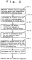
- Fig. 2 is a flowchart representing a procedure for determining an air quality level according to an embodiment of the invention.
- Fig. 3 is a characteristic diagram showing a temperature-humidity characteristic of voltage outputs of a gas sensor used in the embodiment.
- Fig. 4 is an explanatory drawing for explaining output correction in determining an air quality level according to the embodiment.
- Fig. 1 is a block diagram showing an embodiment of air quality level determination apparatus of the invention.
- numeral 11 is air quality sensing means for sensing a state of air quality
- 12 temperature and humidity sensing means for sensing temperature and humidity, wherein the state of air quality, temperature and humidity obtained by both means 11, 12 are provided to computing means 14, and the computing means 14 is adapted to control an air quality regulator 15 on a basis of the state of air quality, temperature and humidity by referring to memory means 13.
- the memory means 13 stores threshold values that provide an absolute determination reference of air quality level, an output value (first output value) of the air quality sensing means 11 that corresponds to clean state in conditions of temperature and humidity under which the threshold values are derived ,and a temperature and humidity correction formula correlated with output values of the air quality sensing means 11, respectively.
- the memory means 13 can be considered as reference value output means, and the temperature and humidity correction formula established between various kinds of temperatures and humidities prestored in the memory means 13 and output values of the air quality sensing means 11 in an air quality that provides the determination reference ,for example air quality in clean state, is considered as relational information.
- the computing means 14 calculates from the temperature and humidity correction formula an output of the air quality sensing means corresponding to clean state at temperature and humidity upon air quality detection. And the computing means 14 calculates and takes as an output correction amount a difference between the calculated value (second output value) and the output value (first output value) of air quality sensing means 11 corresponding to clean state at temperature and humidity providing an absolute determination reference of air quality level, said first output value being prestored in the memory means 13 . And then the computing means 14 adds the output correction amount calculated to an output value of threshold value for air quality determination at the temperature and humidity providing the absolute determination reference of air quality level, said output value of threshold value being prestored in the memory means 13 , thereby correct the output value of threshold value. Further the computing means 14 determines an air quality level by comparing the output of air quality sensing means 11 at air quality detection with the corrected output value of threshold value for air quality determination, and outputs the result as a control signal for controlling an air quality regulator 15.
- an SnO2 semiconducting gas sensor (hereinafter called as a gas sensor) capable of sensing such organic solvents as alcohols, volatile sulfides and nitrogen-containing compounds is used.
- a ceramic thermistor (hereinafter thermistor) is used as a temperature sensor of the temperature and humidity sensing means 12, and a ceramic humidity sensor (hereinafter humidity sensor) as a humidity sensor.
- Fig. 2 is a flowchart showing a procedure for determining an air quality.
- an output of the temperature and humidity sensing means 12 and an output of the air quality sensing means 11 are measured (step 21), and an output value of the air quality sensing means 11 that corresponds to clean state at the temperature and humidity at the air quality detection is calculated by the temperature and humidity correction formula (step 22).
- a difference between the calculated value and an output value of the air quality sensing means 11 ,prestored in the memory means 13, corresponding to clean state at temperature and humidity providing an absolute determination reference of air quality level is calculated ,and is regarded as an output correction amount (step 23).
- the output value of threshold value for air quality level determination is corrected (step 24).
- an air quality level is determined (step 26), and a control signal for controlling the air quality regulator 15 is outputted on the basis of the result.
- an air quality was measured in a laboratory room of approximately 1.5 ⁇ 2 ⁇ 2.2 m in size that is provided with an air conditioner having ventilating and air cleaning functions (hereinafter air quality regulator).
- the gas sensor, thermistor and humidity sensor were attached in mutual vicinity on a wall at a level of approximately 1.2 m.
- Fig. 3 illustrates temperature and humidity characteristics of voltage output (used as a sensor output in the embodiment, and hereinafter called as a sensor output) of the gas sensor used in the embodiment, and a relation between humidities and sensor outputs is shown in a graph with temperature as a parameter.
- temperature and humidity characteristics at 15°C (line a), 25°C (line b) and 35°C (line c) are shown, respectively, as examples.
- the humidity and sensor output (V) are in a proportional relation in a humidity range of 20 to 80%RH, and can be expressed by a general formula (formula 1).
- V A ⁇ [%RH] + B
- A 1.7 ⁇ 10 ⁇ 2 (v/% RH) that represents an inclination
- parameter B 0.07 v (15°C), 0.86 v (25°C) and 1.02 v (35°C), respectively.
- a portion within a range of temperature between 15 and 35°C and humidity between 30 and 70%RH that is enclosed by straight lines is regarded as a temperature and humidity correction range.
- the temperature and humidity correction range is divided into five sections, delimiting the range at temperatures of 19, 23, 27 and 31°C, which are referred to as sections 1, 2, 3, 4 and 5.
- the delimiting temperatures 15, 19, 23, 27 and 31°C are regarded as belonging to the sections 1, 2, 3, 4 and 5, respectively, and temperature 35°C to the section 5.
- a temperature and humidity that provide an absolute determination reference of air quality level are set at 25°C and 50% RH, respectively (shown by a ⁇ in the figure). Therefore, at the temperature and humidity, a sensor output value corresponding to clean state is 1.39 v, and output value of threshold value for air quality level determination is 1.5 v.
- the output value of threshold value for air quality level determination of 1.5 v is an experimental value obtained from a correlation between a sensor output of the air quality sensing means 11 with an air quality load (odor) at 25°C and 50 % RH and discomfort impression (report) of a subject man.
- a temperature and humidity at air quality detection in an experiment for confirming operation of the air quality level determination apparatus were set at 30°C and 65% RH, respectively.
- the sensor output of the air quality sensing means 11 was 1.85 v.
- temperature and humidity conditions of 30°C and 65%RH belong to the section 4.
- V 1.07 ⁇ 10 ⁇ 2 ⁇ [%RH] + 0.92
- the temperature and humidity correction formula 2 is established at an intermediate value (mean value) of temperatures in the divided temperature sections. Therefore, it represents a sensor output at a temperature of 29°C, and is regarded as a temperature and humidity correction formula for calculating a correction amount of sensor output in the section 4.
- a sensor output corresponding to clean state at 30°C, 65% RH (shown by a O in the figure) is calculated to be 1.62 v from the formula 2.
- the sensor output of said 1.85 v at air quality detection was compared with the output of threshold value for air quality level determination of 1.73 v, and it was determined, as a result, that the air quality level is significantly degraded, because 1.85 v > 1.73 v.
- a discomfort report showed a significant discomfort, and then the report was consistent with a determination result based on a sensor output of the air quality level determination apparatus.
- a sensor output can be easily corrected on the basis of temperature and humidity changes, and air quality level is accurately determined.
- conditions of the section 4 are described as an example in the embodiment, correction of a sensor output and determination of an air quality level can be easily performed in the same manner in other sections as well by changing the value of parameter B in the temperature and humidity correction formula, respectively.
- the parameter B in sections 1, 2, 3 and 5 of the embodiment is in the order 0.73 v, 0.79 v, 0.86 v and 0.99 v, respectively.
- the present invention can utilize a tabel equivalent to the above-mentioned formula.
- an equivalent of various gas sensors may be alternatively used.
- plural gas sensors having different gas selectivity may be used, in such case, a factor that causes degradation of air quality can be identified, and air quality can be adjusted more finely at the same time.
- air quality sensing means as optical gas sensing means and chemical gas sensing means can be used according to the particular purpose and size.
- temperature and humidity sensing means of the invention is not limited to such ceramic sensor and ceramic humidity sensor of the embodiment, and arbitrary means may be employed as far as it is capable of sensing temperature and humidity and outputting a signal.
- a threshold value that provides an absolute determination reference of air quality level is corrected in response to a temperature and humidity at air quality detection, an air quality level can be determined, and the air quality is accurately determined.
- an apparatus for determining an air quality level of the invention even when temperature and humidity are varied, a level of air quality can be easily and accurately determined, and air quality can be maintained and controlled at a comfortable level by applying the determination result to an air quality regulator, and properly controlling the air quality regulator.
Landscapes
- Engineering & Computer Science (AREA)
- Combustion & Propulsion (AREA)
- Signal Processing (AREA)
- General Engineering & Computer Science (AREA)
- Mechanical Engineering (AREA)
- Chemical & Material Sciences (AREA)
- Fuzzy Systems (AREA)
- Mathematical Physics (AREA)
- Physics & Mathematics (AREA)
- Air Conditioning Control Device (AREA)
- Investigating Or Analyzing Materials Using Thermal Means (AREA)
- Investigating Or Analyzing Materials By The Use Of Electric Means (AREA)
- Investigating Or Analyzing Materials By The Use Of Fluid Adsorption Or Reactions (AREA)
Applications Claiming Priority (2)
| Application Number | Priority Date | Filing Date | Title |
|---|---|---|---|
| JP274639/92 | 1992-10-13 | ||
| JP4274639A JP3026895B2 (ja) | 1992-10-13 | 1992-10-13 | 空気質レベル判定方法および空気質レベル判定装置 |
Publications (2)
| Publication Number | Publication Date |
|---|---|
| EP0592796A1 true EP0592796A1 (de) | 1994-04-20 |
| EP0592796B1 EP0592796B1 (de) | 1998-11-25 |
Family
ID=17544509
Family Applications (1)
| Application Number | Title | Priority Date | Filing Date |
|---|---|---|---|
| EP93113768A Expired - Lifetime EP0592796B1 (de) | 1992-10-13 | 1993-08-27 | Verfahren und Vorrichtung zur Ermittlung der Luftqualität |
Country Status (4)
| Country | Link |
|---|---|
| US (1) | US5511006A (de) |
| EP (1) | EP0592796B1 (de) |
| JP (1) | JP3026895B2 (de) |
| DE (1) | DE69322229T2 (de) |
Cited By (5)
| Publication number | Priority date | Publication date | Assignee | Title |
|---|---|---|---|---|
| EP0710804A3 (de) * | 1994-11-03 | 1997-12-10 | Carrier Corporation | Anlage zur Innenluft-Qualitätskontrolle für integrierte Räume |
| NL1021562C2 (nl) * | 2002-09-30 | 2004-04-02 | Norbert Peter Vroege | Zelfstandig werkende inrichting voor het geven van informatie inzake luchtkwaliteit. |
| EP1621901A1 (de) * | 2004-07-28 | 2006-02-01 | Michael Siegrist | Mess- und Warngerät |
| US7764180B2 (en) * | 2005-09-14 | 2010-07-27 | Industrial Technology Research Institute | Environment controlling system and method thereof |
| CN104340119A (zh) * | 2014-10-24 | 2015-02-11 | 苏州佑瑞检测技术有限公司 | 一种设有投影装置的轿车车内污染物浓度实时监控方法 |
Families Citing this family (26)
| Publication number | Priority date | Publication date | Assignee | Title |
|---|---|---|---|---|
| EP0789200B1 (de) * | 1996-02-09 | 2001-09-26 | Siemens Building Technologies AG | Verfahren zur sensorgesteuerten Bedarfslüftung und Regler zur Durchführung des Verfahrens |
| US6687640B1 (en) * | 2001-10-23 | 2004-02-03 | Sandia Corporation | Airborne agent concentration analysis |
| US20030129936A1 (en) * | 2002-01-08 | 2003-07-10 | Shaikh Mohammad Ali | Room ventilating apparatus |
| DE102006023182A1 (de) * | 2006-05-17 | 2007-11-22 | Siemens Ag | Sensoranordnung zur Erfassung von Kennwerten der Umgebung und Verfahren zur Generierung entsprechender Ausgangssignale |
| US9846883B2 (en) * | 2007-04-03 | 2017-12-19 | International Business Machines Corporation | Generating customized marketing messages using automatically generated customer identification data |
| US8831972B2 (en) * | 2007-04-03 | 2014-09-09 | International Business Machines Corporation | Generating a customer risk assessment using dynamic customer data |
| US8775238B2 (en) * | 2007-04-03 | 2014-07-08 | International Business Machines Corporation | Generating customized disincentive marketing content for a customer based on customer risk assessment |
| US9626684B2 (en) * | 2007-04-03 | 2017-04-18 | International Business Machines Corporation | Providing customized digital media marketing content directly to a customer |
| US9031858B2 (en) * | 2007-04-03 | 2015-05-12 | International Business Machines Corporation | Using biometric data for a customer to improve upsale ad cross-sale of items |
| US8812355B2 (en) * | 2007-04-03 | 2014-08-19 | International Business Machines Corporation | Generating customized marketing messages for a customer using dynamic customer behavior data |
| US9092808B2 (en) | 2007-04-03 | 2015-07-28 | International Business Machines Corporation | Preferred customer marketing delivery based on dynamic data for a customer |
| US9031857B2 (en) * | 2007-04-03 | 2015-05-12 | International Business Machines Corporation | Generating customized marketing messages at the customer level based on biometric data |
| US9361623B2 (en) | 2007-04-03 | 2016-06-07 | International Business Machines Corporation | Preferred customer marketing delivery based on biometric data for a customer |
| US9685048B2 (en) * | 2007-04-03 | 2017-06-20 | International Business Machines Corporation | Automatically generating an optimal marketing strategy for improving cross sales and upsales of items |
| US20090006125A1 (en) * | 2007-06-29 | 2009-01-01 | Robert Lee Angell | Method and apparatus for implementing digital video modeling to generate an optimal healthcare delivery model |
| US20090083121A1 (en) * | 2007-09-26 | 2009-03-26 | Robert Lee Angell | Method and apparatus for determining profitability of customer groups identified from a continuous video stream |
| US20090089107A1 (en) * | 2007-09-27 | 2009-04-02 | Robert Lee Angell | Method and apparatus for ranking a customer using dynamically generated external data |
| US7987023B2 (en) * | 2008-02-20 | 2011-07-26 | Liebert Corporation | Humidity control for multiple unit A/C system installations |
| US8907803B2 (en) * | 2012-01-09 | 2014-12-09 | Intwine Energy | Networked air quality monitoring |
| US10143608B2 (en) | 2016-09-23 | 2018-12-04 | Stryker Corporation | Systems and methods for determining the usability of person support apparatuses |
| CN111174300B (zh) * | 2018-10-24 | 2021-10-29 | 青岛海尔空调器有限总公司 | 用于可移动空调的控制方法及装置 |
| US11711451B2 (en) | 2018-12-10 | 2023-07-25 | Intwine Connect, Llc | Connected gateway |
| US11434065B2 (en) | 2020-06-08 | 2022-09-06 | Robert C. Danville | Automatic spray dispenser |
| US11609032B2 (en) * | 2020-10-22 | 2023-03-21 | Emerson Climate Technologies, Inc. | Refrigerant leak sensor measurement adjustment systems and methods |
| JP2022174625A (ja) * | 2021-05-11 | 2022-11-24 | 株式会社デンソーウェーブ | 空調制御システム及び空調設備 |
| CN113719938B (zh) * | 2021-08-20 | 2023-06-09 | 深圳市晨北科技有限公司 | 湿度补偿方法和装置、计算机设备以及介质 |
Citations (3)
| Publication number | Priority date | Publication date | Assignee | Title |
|---|---|---|---|---|
| WO1989012269A1 (en) * | 1988-06-10 | 1989-12-14 | Honeywell Inc. | A method for the optimal comfort and efficiency control of variable speed heat pumps and air conditioners |
| EP0405149A2 (de) * | 1989-06-29 | 1991-01-02 | Omron Corporation | Apparat zur Klimaregelung eines Raumes |
| EP0518327A2 (de) * | 1991-06-14 | 1992-12-16 | Matsushita Electric Industrial Co., Ltd. | Klimaanlage |
Family Cites Families (5)
| Publication number | Priority date | Publication date | Assignee | Title |
|---|---|---|---|---|
| US4690041A (en) * | 1985-03-19 | 1987-09-01 | Commonwealth Scientific And Industrial Research Organization | Prevention, arresting and removal of accumulation of moisture in bunker storages |
| US5147429A (en) * | 1990-04-09 | 1992-09-15 | James Bartholomew | Mobile airborne air cleaning station |
| US5215498A (en) * | 1991-03-04 | 1993-06-01 | Gaztech International Corporation | Ventilation controller |
| US5290200A (en) * | 1991-03-06 | 1994-03-01 | Professional Supply, Inc. | Detection and evacuation of atmospheric pollutants from a confined work place |
| US5259812A (en) * | 1992-09-23 | 1993-11-09 | Kleinsek Don A | Clean room and clean room containment center |
-
1992
- 1992-10-13 JP JP4274639A patent/JP3026895B2/ja not_active Expired - Fee Related
-
1993
- 1993-08-09 US US08/103,124 patent/US5511006A/en not_active Expired - Fee Related
- 1993-08-27 DE DE69322229T patent/DE69322229T2/de not_active Expired - Fee Related
- 1993-08-27 EP EP93113768A patent/EP0592796B1/de not_active Expired - Lifetime
Patent Citations (3)
| Publication number | Priority date | Publication date | Assignee | Title |
|---|---|---|---|---|
| WO1989012269A1 (en) * | 1988-06-10 | 1989-12-14 | Honeywell Inc. | A method for the optimal comfort and efficiency control of variable speed heat pumps and air conditioners |
| EP0405149A2 (de) * | 1989-06-29 | 1991-01-02 | Omron Corporation | Apparat zur Klimaregelung eines Raumes |
| EP0518327A2 (de) * | 1991-06-14 | 1992-12-16 | Matsushita Electric Industrial Co., Ltd. | Klimaanlage |
Cited By (6)
| Publication number | Priority date | Publication date | Assignee | Title |
|---|---|---|---|---|
| EP0710804A3 (de) * | 1994-11-03 | 1997-12-10 | Carrier Corporation | Anlage zur Innenluft-Qualitätskontrolle für integrierte Räume |
| NL1021562C2 (nl) * | 2002-09-30 | 2004-04-02 | Norbert Peter Vroege | Zelfstandig werkende inrichting voor het geven van informatie inzake luchtkwaliteit. |
| WO2004029517A1 (en) * | 2002-09-30 | 2004-04-08 | Vroege, Norbert, Peter | Device for determining the quality of ambient air |
| EP1621901A1 (de) * | 2004-07-28 | 2006-02-01 | Michael Siegrist | Mess- und Warngerät |
| US7764180B2 (en) * | 2005-09-14 | 2010-07-27 | Industrial Technology Research Institute | Environment controlling system and method thereof |
| CN104340119A (zh) * | 2014-10-24 | 2015-02-11 | 苏州佑瑞检测技术有限公司 | 一种设有投影装置的轿车车内污染物浓度实时监控方法 |
Also Published As
| Publication number | Publication date |
|---|---|
| US5511006A (en) | 1996-04-23 |
| EP0592796B1 (de) | 1998-11-25 |
| DE69322229D1 (de) | 1999-01-07 |
| DE69322229T2 (de) | 1999-04-22 |
| JPH06123723A (ja) | 1994-05-06 |
| JP3026895B2 (ja) | 2000-03-27 |
Similar Documents
| Publication | Publication Date | Title |
|---|---|---|
| EP0592796A1 (de) | Verfahren und Vorrichtung zur Ermittlung der Luftqualität | |
| US6526801B2 (en) | Method of compensating for drift in gas sensing equipment | |
| US6549826B1 (en) | VAV airflow control for preventing processor overflow and underflow | |
| EP1816455A1 (de) | Verfahren und Systeme zur Temperaturbestimmung eines Objekts | |
| US20070016337A1 (en) | Vehicle-borne electronic control device | |
| JP5416055B2 (ja) | Tvocの検出方法、検出装置および外気導入量制御システム | |
| JP2008275557A (ja) | ガス警報器 | |
| CN101087993A (zh) | 用于监控传感器功能的方法 | |
| JP3391436B2 (ja) | 炭酸ガス濃度測定装置 | |
| KR20230019644A (ko) | 가스 센서를 자가 보정하는 방법 및 상기 방법을 수행하는 가스 센서 보정 시스템 | |
| CN107576695B (zh) | 电化学气体传感器及其校准方法、空调器 | |
| CN110986266A (zh) | 设备控制方法、控制器及空调机组 | |
| CN114237031B (zh) | 空间臭氧浓度控制方法 | |
| KR100531320B1 (ko) | 공기 청정기의 제어장치 및 그 제어방법 | |
| JPH06130014A (ja) | 空気質レベル判定方法および空気質レベル判定装置 | |
| CN110006957B (zh) | 气体检测系统 | |
| JPH06281477A (ja) | 連続分析装置 | |
| JPH11118617A (ja) | 温度調節器 | |
| KR0149632B1 (ko) | 가스센서 오염보정장치 및 제어방법 | |
| KR20000007693A (ko) | 가스감지방법 및 이를 이용한 가스감지장치 | |
| JP2786366B2 (ja) | 炭酸ガス濃度検知装置 | |
| JPH05307018A (ja) | 炭酸ガス濃度検知装置 | |
| JP3024895B2 (ja) | 空気質検知装置 | |
| JP3255897B2 (ja) | 空気質検知装置 | |
| JPH07260730A (ja) | 環境センサ出力補正装置 |
Legal Events
| Date | Code | Title | Description |
|---|---|---|---|
| PUAI | Public reference made under article 153(3) epc to a published international application that has entered the european phase |
Free format text: ORIGINAL CODE: 0009012 |
|
| AK | Designated contracting states |
Kind code of ref document: A1 Designated state(s): DE FR GB |
|
| 17P | Request for examination filed |
Effective date: 19940913 |
|
| 17Q | First examination report despatched |
Effective date: 19951107 |
|
| GRAG | Despatch of communication of intention to grant |
Free format text: ORIGINAL CODE: EPIDOS AGRA |
|
| GRAG | Despatch of communication of intention to grant |
Free format text: ORIGINAL CODE: EPIDOS AGRA |
|
| GRAH | Despatch of communication of intention to grant a patent |
Free format text: ORIGINAL CODE: EPIDOS IGRA |
|
| GRAH | Despatch of communication of intention to grant a patent |
Free format text: ORIGINAL CODE: EPIDOS IGRA |
|
| GRAA | (expected) grant |
Free format text: ORIGINAL CODE: 0009210 |
|
| AK | Designated contracting states |
Kind code of ref document: B1 Designated state(s): DE FR GB |
|
| REF | Corresponds to: |
Ref document number: 69322229 Country of ref document: DE Date of ref document: 19990107 |
|
| ET | Fr: translation filed | ||
| PLBE | No opposition filed within time limit |
Free format text: ORIGINAL CODE: 0009261 |
|
| 26N | No opposition filed | ||
| REG | Reference to a national code |
Ref country code: GB Ref legal event code: IF02 |
|
| PGFP | Annual fee paid to national office [announced via postgrant information from national office to epo] |
Ref country code: FR Payment date: 20040810 Year of fee payment: 12 |
|
| PGFP | Annual fee paid to national office [announced via postgrant information from national office to epo] |
Ref country code: GB Payment date: 20040825 Year of fee payment: 12 |
|
| PGFP | Annual fee paid to national office [announced via postgrant information from national office to epo] |
Ref country code: DE Payment date: 20040902 Year of fee payment: 12 |
|
| PG25 | Lapsed in a contracting state [announced via postgrant information from national office to epo] |
Ref country code: GB Free format text: LAPSE BECAUSE OF NON-PAYMENT OF DUE FEES Effective date: 20050827 |
|
| PG25 | Lapsed in a contracting state [announced via postgrant information from national office to epo] |
Ref country code: DE Free format text: LAPSE BECAUSE OF NON-PAYMENT OF DUE FEES Effective date: 20060301 |
|
| GBPC | Gb: european patent ceased through non-payment of renewal fee |
Effective date: 20050827 |
|
| PG25 | Lapsed in a contracting state [announced via postgrant information from national office to epo] |
Ref country code: FR Free format text: LAPSE BECAUSE OF NON-PAYMENT OF DUE FEES Effective date: 20060428 |
|
| REG | Reference to a national code |
Ref country code: FR Ref legal event code: ST Effective date: 20060428 |