EP0592817B1 - Installation de turbine à gaz avec machine à ondes de pression - Google Patents
Installation de turbine à gaz avec machine à ondes de pression Download PDFInfo
- Publication number
- EP0592817B1 EP0592817B1 EP93114657A EP93114657A EP0592817B1 EP 0592817 B1 EP0592817 B1 EP 0592817B1 EP 93114657 A EP93114657 A EP 93114657A EP 93114657 A EP93114657 A EP 93114657A EP 0592817 B1 EP0592817 B1 EP 0592817B1
- Authority
- EP
- European Patent Office
- Prior art keywords
- pressure
- turbine
- compressor
- medium
- gas
- Prior art date
- Legal status (The legal status is an assumption and is not a legal conclusion. Google has not performed a legal analysis and makes no representation as to the accuracy of the status listed.)
- Expired - Lifetime
Links
Images

Classifications
-
- F—MECHANICAL ENGINEERING; LIGHTING; HEATING; WEAPONS; BLASTING
- F02—COMBUSTION ENGINES; HOT-GAS OR COMBUSTION-PRODUCT ENGINE PLANTS
- F02C—GAS-TURBINE PLANTS; AIR INTAKES FOR JET-PROPULSION PLANTS; CONTROLLING FUEL SUPPLY IN AIR-BREATHING JET-PROPULSION PLANTS
- F02C3/00—Gas-turbine plants characterised by the use of combustion products as the working fluid
- F02C3/02—Gas-turbine plants characterised by the use of combustion products as the working fluid using exhaust-gas pressure in a pressure exchanger to compress combustion-air
Definitions
- the invention relates to a gas turbine group according to the preamble of patent claim 1.
- Such a gas turbine group is e.g. known from EP-A-0 212 181.
- a first outlet opening of the pressure wave machine is connected to the high pressure turbine and a second outlet opening of the pressure wave machine is connected to the low pressure turbine together with the outlet of the high pressure turbine.
- the object which is to be achieved with the present invention is to create a gas turbine group which is able to optimally process the pressure drop of two hot gas streams of different pressure emerging from the pressure wave machine and to improve the efficiency of the turbine by improving the expansion process increase.
- the use of a double spiral has the advantage that more pressure drops and more volume flow can be processed at the same time.
- the radial turbine with a double spiral can replace two turbines, namely a high-pressure turbine and a medium-pressure turbine, the efficiency being additionally improved. It is particularly advantageous that the parallel expansion of two hot gas mass flows from the high-pressure propellant line and from the low-pressure propellant line results in thorough mixing at the outlet of the radial turbine with a double spiral.
- the parallel expansion of the high pressure and medium pressure partial flow in just one turbine makes it possible to change the performance of the high pressure medium pressure turbine within certain limits. This enables the performance balances or the individual components to be optimized better.
- the low pressure turbine can in this case be an independent, i.e. free-running power turbine are operated.
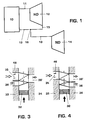
- a pressure wave machine 10 is connected to a high pressure turbine 12 via a high pressure propellant gas line 11 and to a low pressure turbine 14 via a low pressure propellant gas line 13.
- An outlet line 15 of the high-pressure turbine 12 opens at the branch 16 into the low-pressure propellant gas line 13.
- a pressure wave machine 19 is arranged between a high-pressure compressor 17 and a high-pressure medium-pressure turbine 18.
- This pressure wave machine 19 has isocore combustion chambers 42.
- a low-pressure compressor 20 is connected to the high-pressure compressor 17 and a low-pressure turbine 21 is connected to the high-pressure medium-pressure turbine 18.
- a combustion chamber 43 with a burner 44 is located between the high-pressure medium-pressure turbine 18 and the low-pressure turbine 21.
- a turbine wheel 22 of the high-pressure medium-pressure turbine 18 drives a compressor wheel 24 of the high-pressure compressor 17 via a first shaft 23.
- a turbine wheel 25 of the low-pressure turbine 21 drives a compressor wheel 27 of the low-pressure compressor 20 via a second shaft 26.
- a generator 28 is driven by the turbine wheel 25 of the low-pressure turbine 21 via the same second shaft 26. If the total compressor output of the high-pressure compressor 17 and the low-pressure compressor 20 with the high-pressure medium-pressure turbine 18 is to be generated, the compressor wheel 27 is connected to the first shaft 23. In this case, only the generator 28 is driven by the turbine wheel 25 of the low-pressure turbine 21 via the second shaft 26.
- the generator 28 is also to be driven by the turbine wheel 22 of the high-pressure medium-pressure turbine 18, the turbine wheel 25 and also the generator 28 are connected to the first shaft 23 and the second shaft 26 can be omitted entirely.
- Both the high-pressure compressor 17 and the high-pressure medium-pressure turbine 18 are designed as radial compressors or as a radial turbine.
- the low-pressure compressor 20 and the low-pressure turbine 21 are designed as an axial compressor or as an axial turbine.
- the high-pressure medium-pressure turbine 18 has a double spiral 30, 31.
- the pressure wave machine 19 has a cellular wheel 32 which is rotatably mounted on the first shaft 23 and contains the isocore combustion chambers 42.
- This cellular wheel 32 is located in a housing of the pressure wave machine 19. Of this housing, only two side walls 33 and 34 are indicated in FIG. 2. These side walls 33 and 34 have inlet channels 35 and outlet channels 36.
- the inlet channels 35 are - as indicated by arrows 39, 40 - connected to the high-pressure compressor 17 by lines, not shown, and the outlet channels 36 are - as indicated by arrows 37 and 38 - by a high-pressure propellant gas line 37, not shown, and a medium-pressure propellant gas line 38, not shown, connected to the double spiral 30 and 31 of the high-pressure medium-pressure turbine 18.
- the two hot gas streams from the double spiral 30, 31 are mixed with one another and pass through the combustion chamber 43 into the low-pressure turbine 21 is heated before it reaches the low-pressure turbine 21.
- the high-pressure compressor and the low-pressure compressor are driven by this hot gas stream flowing through the high-pressure medium-pressure turbine and the hot gas flow then flowing through the low-pressure turbine drives the generator 28.
- This turbine replaces two small radial turbines, namely a high pressure and a medium pressure turbine. Due to the parallel expansion of the two hot gas streams, thorough mixing is achieved at the turbine outlet.
- the parallel expansion of a high-pressure and a medium-pressure partial flow in a single turbine gives the possibility to change the performance of the high-pressure medium-pressure turbine within certain limits. This enables the performance balances or the individual components to be optimized better.
- the low pressure turbine can in this case be an independent, i.e. be operated as a free-running power turbine.
- the pressure wave machine 19 can be designed as a countercurrent machine.
- the cellular wheel 32 is located between the two side walls 33 and 34.
- the air-side side wall 33 has an inlet opening 35, which is connected to the compressor 17 and contains fuel nozzles 46, and an outlet opening 36, which connects to the first part 30 of the double spiral 30, 31 is connected.
- the gas side wall 34 only has an outlet opening 36 ', which is connected to the second part 31 of the double spiral 30, 31.
- the pressure wave machine 19 can be designed as a DC machine.
- the cellular wheel 32 is located between the two side walls 33 and 34.
- the air-side side wall 33 has only one inlet opening 35, which is connected to the compressor 17 and contains fuel nozzles 46.
- the gas-side wall 34 has two outlet openings 36 and 36 ', of which one outlet opening 36 is connected to the first part 30 of the double spiral 30, 31, and of which the other outlet opening 36' is connected to the second part 31 of the double spiral 30, 31 connected.
- the gas turbine group described can be used to drive a generator 28.
- the gas turbine group described can be used as a jet turbine for an aircraft.
Landscapes
- Engineering & Computer Science (AREA)
- Chemical & Material Sciences (AREA)
- Combustion & Propulsion (AREA)
- Mechanical Engineering (AREA)
- General Engineering & Computer Science (AREA)
- Structures Of Non-Positive Displacement Pumps (AREA)
Claims (8)
- Turbogroupe à gaz comprenant une turbine (18) avec au moins un étage à haute pression (30) et un étage à moyenne pression (31), au moins une chambre de combustion, dans laquelle cette chambre de combustion présente la forme d'une machine à ondes de pression (19), avec une roue cellulaire (32) qui tourne entre des parties latérales (33, 34) côté air et côté gaz pourvues chacune d'ouvertures d'entrée et de sortie (35, 36, 36'), caractérisé en ce que- l'étage à haute pression (30) et l'étage à moyenne pression (31) sont rassemblés dans une turbine à haute et moyenne pression (18), qui constitue une turbine radiale; en ce que- la turbine à haute et moyenne pression (18) présente une double spirale (30, 31), dont l'une des spirales (30) est raccordée à une première ouverture de sortie (36) de la machine à ondes de pression (19) et dont l'autre spirale (31) est raccordée à une deuxième ouverture de sortie (36') de la machine à ondes de pression (19); et en ce que- la turbine radiale est constituée avec une seule roue de turbine radiale (22), dans laquelle les courants de gaz chauds des deux parties de la double spirale (30, 31) se mélangent.
- Turbogroupe à gaz selon la revendication 1, caractérisé en ce que la machine à ondes de pression (19) est constituée par une machine à contre-pression, avec une paroi latérale (33) du côté air, qui présente une ouverture d'entrée (35) qui est raccordée à un compresseur (17), ainsi qu'une ouverture de sortie (36), qui est raccordée à la première partie (30) de la double spirale (30, 31), et avec une paroi latérale (34) coté gaz, qui présente une ouverture de sortie (36') qui est raccordée à la seconde partie (31) de la double spirale (30, 31) de la turbine à haute et moyenne pression (18).
- Turbogroupe à gaz selon la revendication 1, caractérisé en ce que la machine à ondes de pression (19) est constituée par une machine à courant continu, avec une paroi latérale (33) du côté air, qui présente une ouverture d'entrée (35) qui est raccordée à un compresseur (17), et avec une paroi latérale (34) du côté gaz, qui présente deux ouvertures de sortie (36, 36') dont l'une des ouvertures de sortie (36) est raccordée à la première partie (30) de la double spirale (30, 31) et dont l'autre ouverture de sortie (36') est raccordée à l'autre partie (31) de la double spirale (30, 31) de la turbine à haute et moyenne pression (18).
- Turbogroupe à gaz selon la revendication 1, comprenant en outre un compresseur qui est composé d'un compresseur à haute pression (17) et d'un compresseur à basse pression (20), un générateur (28) entraîné par la turbine (18, 21), un arbre (23, 26) qui relie une roue de turbine (22, 25) de la turbine (18, 21) à une roue de compresseur (24, 27) du compresseur (17, 20) et au générateur (28), caractérisé en ce que- l'arbre (23, 26) présente deux arbres concentriques (23, 26); en ce que- la roue de turbine (22, 25) présente deux roues de turbine séparées; en ce que- la roue de compresseur (24, 27) présente deux roues de compresseur séparées; en ce que- la roue de turbine (22) de la turbine à haute et moyenne pression (18) est reliée par le premier arbre (23) aux roues de compresseur (24, 27) du compresseur à haute et basse pression (17, 20); et en ce que- la roue de turbine (25) de la turbine à basse pression (21) est reliée par l'arbre (26) au générateur (28).
- Turbogroupe à gaz selon la revendication 4, caractérisé en ce que l'arbre (23) relie la roue de turbine (22) à la roue de compresseur (24) et l'arbre (26) relie la roue de turbine (25) à la roue de compresseur (27) ainsi qu'au générateur (28).
- Turbogroupe à gaz selon la revendication 1, caractérisé en ce que le turbogroupe à gaz sert d'unité stationnaire pour l'entraînement d'un générateur (28).
- Turbogroupe à gaz selon la revendication 1, caractérisé en ce que le turbogroupe à gaz sert de turbine à réaction pour un avion et présente à l'avant un soufflant avant (45).
- Turbogroupe à gaz selon la revendication 1, caractérisé en ce qu'une autre chambre de combustion (43) est disposée en aval de la turbine à haute et moyenne pression (18).
Applications Claiming Priority (2)
| Application Number | Priority Date | Filing Date | Title |
|---|---|---|---|
| DE4234248A DE4234248A1 (de) | 1992-10-10 | 1992-10-10 | Gasturbogruppe |
| DE4234248 | 1992-10-10 |
Publications (2)
| Publication Number | Publication Date |
|---|---|
| EP0592817A1 EP0592817A1 (fr) | 1994-04-20 |
| EP0592817B1 true EP0592817B1 (fr) | 1996-12-11 |
Family
ID=6470193
Family Applications (1)
| Application Number | Title | Priority Date | Filing Date |
|---|---|---|---|
| EP93114657A Expired - Lifetime EP0592817B1 (fr) | 1992-10-10 | 1993-09-13 | Installation de turbine à gaz avec machine à ondes de pression |
Country Status (3)
| Country | Link |
|---|---|
| EP (1) | EP0592817B1 (fr) |
| JP (1) | JPH06221182A (fr) |
| DE (2) | DE4234248A1 (fr) |
Families Citing this family (4)
| Publication number | Priority date | Publication date | Assignee | Title |
|---|---|---|---|---|
| DE4331081A1 (de) * | 1993-09-13 | 1995-03-16 | Abb Management Ag | Verfahren zum Betrieb einer Gasturbinenanlage |
| US7555891B2 (en) | 2004-11-12 | 2009-07-07 | Board Of Trustees Of Michigan State University | Wave rotor apparatus |
| WO2012116285A2 (fr) | 2011-02-25 | 2012-08-30 | Board Of Trustees Of Michigan State University | Appareil de moteur à disque à ondes |
| PL439009A1 (pl) * | 2021-09-22 | 2023-03-27 | Sieć Badawcza Łukasiewicz-Instytut Lotnictwa | Komora spalania wstępnego do zasilania turbiny w silnikach rakietowych na ciekłe materiały pędne |
Family Cites Families (8)
| Publication number | Priority date | Publication date | Assignee | Title |
|---|---|---|---|---|
| US2705867A (en) * | 1949-06-30 | 1955-04-12 | Curtiss Wright Corp | Engine having a rotor with a plurality of circumferentially-spaced combustion chambers |
| DE955558C (de) * | 1952-04-20 | 1957-01-03 | Max Adolf Mueller Dipl Ing | Strahltriebwerk |
| GB1110302A (en) * | 1966-06-17 | 1968-04-18 | Rolls Royce | Pressure exchanger |
| US4111598A (en) * | 1974-04-30 | 1978-09-05 | Kabushiki Kaisha Komatsu Seisakusho | Turbine casing for superchargers |
| CH668807A5 (de) * | 1985-07-31 | 1989-01-31 | Bbc Brown Boveri & Cie | Gasturbine mit einer druckwellenmaschine als hochdruckverdichterteil. |
| GB2189844A (en) * | 1986-04-30 | 1987-11-04 | Rolls Royce | Gas turbine engines |
| JPH0192531A (ja) * | 1987-10-05 | 1989-04-11 | Hitachi Ltd | 可変容量排気タービン過給機 |
| DE4113680A1 (de) * | 1991-03-12 | 1992-09-17 | Asea Brown Boveri | Gasturbogruppe |
-
1992
- 1992-10-10 DE DE4234248A patent/DE4234248A1/de not_active Withdrawn
-
1993
- 1993-09-13 EP EP93114657A patent/EP0592817B1/fr not_active Expired - Lifetime
- 1993-09-13 DE DE59304743T patent/DE59304743D1/de not_active Expired - Fee Related
- 1993-10-08 JP JP5252939A patent/JPH06221182A/ja active Pending
Also Published As
| Publication number | Publication date |
|---|---|
| JPH06221182A (ja) | 1994-08-09 |
| DE59304743D1 (de) | 1997-01-23 |
| DE4234248A1 (de) | 1994-04-14 |
| EP0592817A1 (fr) | 1994-04-20 |
Similar Documents
| Publication | Publication Date | Title |
|---|---|---|
| DE60133629T2 (de) | Verfahren zum betrieb einer gasturbine mit verstellbaren leitschaufeln | |
| EP0516995B1 (fr) | Centrale combinée à gaz et à vapeur | |
| DE2913548C2 (de) | Wellenkühlung für ein Gasturbinentriebwerk | |
| EP1245804B1 (fr) | Turbine à gaz | |
| EP1084327B1 (fr) | Turbine a gaz ainsi que procede pour le refroidissement d'un etage de turbine | |
| DE2422105C2 (de) | Mehrstrom-Gasturbinen-Strahltriebwerk | |
| DE2454054C2 (de) | Einwelliges Grundtriebwerk für Zweistrom-Gasturbinentriebwerke | |
| DE10236324A1 (de) | Verfahren zum Kühlen von Turbinenschaufeln | |
| DE102009003406A1 (de) | Verfahren und System zur Unterstützung einer Modifikation eines Kombikreislauf-Arbeitsfluids und dessen Verbrennung | |
| EP0462458B1 (fr) | Méthode d'augmentation du taux de compression d'un compresseur d'une installation de turbine à gaz | |
| DE1751851B2 (de) | Gasturbinenanlage | |
| DE112012002692B4 (de) | Vorrichtung und Verfahren zur Reduzierung des Luftmassenflusses zur emissionsarmen Verbrennung über einen erweiterten Bereich in einwelligen Gasturbinen | |
| DE2046810A1 (de) | Gasturbine | |
| DE2849924A1 (de) | Zufuehrung der abgase von einem verbrennungsmotor zum laufrad einer zentripetalturbine eines abgasturboladers | |
| DE1428220B2 (de) | Mantelstrom Gasturbinenstrahltrieb werk in Zweiwellenbauart | |
| EP0924406A1 (fr) | Turbine à gaz avec un générateur de vapeur et un récupérateur disposés en parallèle dans les gaz d'échappement | |
| EP0592817B1 (fr) | Installation de turbine à gaz avec machine à ondes de pression | |
| EP1117913B1 (fr) | Prechauffage du combustible dans une turbine a gaz | |
| EP1262637A1 (fr) | Méthode et dispositif pour une centrale de turbine à gaz | |
| CH189934A (de) | Ein- oder mehrgehäusiger, vielstufiger Axialverdichter mit mindestens einem aussenliegenden Zwischenkühler. | |
| DE69109173T2 (de) | Hochdruck-Zweiwellengasturbine mit Radialrotoren. | |
| DE3500447C2 (de) | Gasturbinenstrahltriebwerk | |
| DE640350C (de) | Gasturbinenanlage mit Gleichdruckverbrennung des Treibmittels | |
| DE102012013622B4 (de) | Raketentriebwerk, insbesondere Flüssigkeitsraketentriebwerk | |
| DE852783C (de) | Turbinenanlage mit mindestens zwei hintereinandergeschalteten Turbinen |
Legal Events
| Date | Code | Title | Description |
|---|---|---|---|
| PUAI | Public reference made under article 153(3) epc to a published international application that has entered the european phase |
Free format text: ORIGINAL CODE: 0009012 |
|
| AK | Designated contracting states |
Kind code of ref document: A1 Designated state(s): CH DE GB LI |
|
| 17P | Request for examination filed |
Effective date: 19940907 |
|
| 17Q | First examination report despatched |
Effective date: 19950706 |
|
| GRAG | Despatch of communication of intention to grant |
Free format text: ORIGINAL CODE: EPIDOS AGRA |
|
| GRAH | Despatch of communication of intention to grant a patent |
Free format text: ORIGINAL CODE: EPIDOS IGRA |
|
| GRAH | Despatch of communication of intention to grant a patent |
Free format text: ORIGINAL CODE: EPIDOS IGRA |
|
| GRAA | (expected) grant |
Free format text: ORIGINAL CODE: 0009210 |
|
| AK | Designated contracting states |
Kind code of ref document: B1 Designated state(s): CH DE GB LI |
|
| REF | Corresponds to: |
Ref document number: 59304743 Country of ref document: DE Date of ref document: 19970123 |
|
| GBT | Gb: translation of ep patent filed (gb section 77(6)(a)/1977) |
Effective date: 19970227 |
|
| PLBE | No opposition filed within time limit |
Free format text: ORIGINAL CODE: 0009261 |
|
| 26N | No opposition filed | ||
| PGFP | Annual fee paid to national office [announced via postgrant information from national office to epo] |
Ref country code: GB Payment date: 19990813 Year of fee payment: 7 |
|
| PGFP | Annual fee paid to national office [announced via postgrant information from national office to epo] |
Ref country code: CH Payment date: 19990816 Year of fee payment: 7 |
|
| PGFP | Annual fee paid to national office [announced via postgrant information from national office to epo] |
Ref country code: DE Payment date: 19990820 Year of fee payment: 7 |
|
| PG25 | Lapsed in a contracting state [announced via postgrant information from national office to epo] |
Ref country code: GB Free format text: LAPSE BECAUSE OF NON-PAYMENT OF DUE FEES Effective date: 20000913 |
|
| PG25 | Lapsed in a contracting state [announced via postgrant information from national office to epo] |
Ref country code: LI Free format text: LAPSE BECAUSE OF NON-PAYMENT OF DUE FEES Effective date: 20000930 Ref country code: CH Free format text: LAPSE BECAUSE OF NON-PAYMENT OF DUE FEES Effective date: 20000930 |
|
| GBPC | Gb: european patent ceased through non-payment of renewal fee |
Effective date: 20000913 |
|
| REG | Reference to a national code |
Ref country code: CH Ref legal event code: PL |
|
| PG25 | Lapsed in a contracting state [announced via postgrant information from national office to epo] |
Ref country code: DE Free format text: LAPSE BECAUSE OF NON-PAYMENT OF DUE FEES Effective date: 20010601 |