EP0592820A1 - Dispositif pour le transport de matériel d'emballage en forme de bande - Google Patents
Dispositif pour le transport de matériel d'emballage en forme de bande Download PDFInfo
- Publication number
- EP0592820A1 EP0592820A1 EP93114711A EP93114711A EP0592820A1 EP 0592820 A1 EP0592820 A1 EP 0592820A1 EP 93114711 A EP93114711 A EP 93114711A EP 93114711 A EP93114711 A EP 93114711A EP 0592820 A1 EP0592820 A1 EP 0592820A1
- Authority
- EP
- European Patent Office
- Prior art keywords
- drum
- material web
- conveyor
- blanks
- elevations
- Prior art date
- Legal status (The legal status is an assumption and is not a legal conclusion. Google has not performed a legal analysis and makes no representation as to the accuracy of the status listed.)
- Granted
Links
Images


Classifications
-
- B—PERFORMING OPERATIONS; TRANSPORTING
- B65—CONVEYING; PACKING; STORING; HANDLING THIN OR FILAMENTARY MATERIAL
- B65H—HANDLING THIN OR FILAMENTARY MATERIAL, e.g. SHEETS, WEBS, CABLES
- B65H27/00—Special constructions, e.g. surface features, of feed or guide rollers for webs
-
- B—PERFORMING OPERATIONS; TRANSPORTING
- B65—CONVEYING; PACKING; STORING; HANDLING THIN OR FILAMENTARY MATERIAL
- B65B—MACHINES, APPARATUS OR DEVICES FOR, OR METHODS OF, PACKAGING ARTICLES OR MATERIALS; UNPACKING
- B65B19/00—Packaging rod-shaped or tubular articles susceptible to damage by abrasion or pressure, e.g. cigarettes, cigars, macaroni, spaghetti, drinking straws or welding electrodes
- B65B19/02—Packaging cigarettes
- B65B19/22—Wrapping the cigarettes; Packaging the cigarettes in containers formed by folding wrapping material around formers
- B65B19/228—Preparing and feeding blanks
-
- B—PERFORMING OPERATIONS; TRANSPORTING
- B65—CONVEYING; PACKING; STORING; HANDLING THIN OR FILAMENTARY MATERIAL
- B65H—HANDLING THIN OR FILAMENTARY MATERIAL, e.g. SHEETS, WEBS, CABLES
- B65H45/00—Folding thin material
- B65H45/12—Folding articles or webs with application of pressure to define or form crease lines
- B65H45/20—Zig-zag folders
-
- B—PERFORMING OPERATIONS; TRANSPORTING
- B65—CONVEYING; PACKING; STORING; HANDLING THIN OR FILAMENTARY MATERIAL
- B65H—HANDLING THIN OR FILAMENTARY MATERIAL, e.g. SHEETS, WEBS, CABLES
- B65H2404/00—Parts for transporting or guiding the handled material
- B65H2404/10—Rollers
- B65H2404/13—Details of longitudinal profile
- B65H2404/131—Details of longitudinal profile shape
- B65H2404/1316—Details of longitudinal profile shape stepped or grooved
-
- B—PERFORMING OPERATIONS; TRANSPORTING
- B65—CONVEYING; PACKING; STORING; HANDLING THIN OR FILAMENTARY MATERIAL
- B65H—HANDLING THIN OR FILAMENTARY MATERIAL, e.g. SHEETS, WEBS, CABLES
- B65H2404/00—Parts for transporting or guiding the handled material
- B65H2404/10—Rollers
- B65H2404/14—Roller pairs
- B65H2404/141—Roller pairs with particular shape of cross profile
- B65H2404/1414—Roller pairs with particular shape of cross profile complementary relief
-
- B—PERFORMING OPERATIONS; TRANSPORTING
- B65—CONVEYING; PACKING; STORING; HANDLING THIN OR FILAMENTARY MATERIAL
- B65H—HANDLING THIN OR FILAMENTARY MATERIAL, e.g. SHEETS, WEBS, CABLES
- B65H2404/00—Parts for transporting or guiding the handled material
- B65H2404/10—Rollers
- B65H2404/15—Roller assembly, particular roller arrangement
- B65H2404/153—Arrangements of rollers facing a transport surface
- B65H2404/1532—Arrangements of rollers facing a transport surface the transport surface being a belt
-
- B—PERFORMING OPERATIONS; TRANSPORTING
- B65—CONVEYING; PACKING; STORING; HANDLING THIN OR FILAMENTARY MATERIAL
- B65H—HANDLING THIN OR FILAMENTARY MATERIAL, e.g. SHEETS, WEBS, CABLES
- B65H2404/00—Parts for transporting or guiding the handled material
- B65H2404/10—Rollers
- B65H2404/18—Rollers composed of several layers
- B65H2404/181—Rollers composed of several layers with cavities or projections at least at one layer
-
- B—PERFORMING OPERATIONS; TRANSPORTING
- B65—CONVEYING; PACKING; STORING; HANDLING THIN OR FILAMENTARY MATERIAL
- B65H—HANDLING THIN OR FILAMENTARY MATERIAL, e.g. SHEETS, WEBS, CABLES
- B65H2404/00—Parts for transporting or guiding the handled material
- B65H2404/10—Rollers
- B65H2404/18—Rollers composed of several layers
- B65H2404/182—Rollers composed of several layers with emery paper like coating (gripping, anti-slip)
Definitions
- the invention relates to a device for transporting material webs, in particular webs of packaging material, with lateral recesses and / or openings and / or projections arranged at regular intervals from one another by endless conveyors, in particular by at least one conveying drum, the material web resting against the endless conveyor during transport .
- the exact, positionally accurate transport of material webs is particularly important in packaging technology if the material web is used to produce blanks.
- the blanks are usually provided with a print, whereby the exact separation of the blanks from the material web is required.
- These are for paper webs Provide print marks for exact control of conveying and drive elements, which are scanned by fixed print mark readers.
- the invention relates to the transport of material webs, in particular of thin cardboard, for producing corresponding blanks, primarily for hinged boxes (hinge-lid packs) for holding cigarettes.
- the blanks for this type of pack have a characteristic structure worldwide with a special shape at the end areas of the elongated blanks.
- the special design characteristics result on the one hand from a protrusion arranged at the end on the cover side for a cover inner flap and on the other hand through inclined surfaces in the area of side folding flaps (side flaps). If material webs with blanks oriented transversely to the longitudinal direction thereof are formed from such a blank, projections and depressions result at the edges.
- An example of such a material web is the subject of US Pat. No. 4,898,569.
- the blanks within the material web are not only pre-punched on the longitudinal edges thereof, but also in the transverse direction by attaching the punchings of the side folding flaps which are customary in a folding box.
- the connection between adjacent blanks within the material web is designed so that only residual connections, namely small, detachable or tearable material webs remain.
- the invention is based on the object of enabling a positionally correct transport of material webs of the type mentioned at the outset without optoelectronic control elements, in particular for forming a formation from zigzag folded blanks.
- the device according to the invention is characterized in that elevations or projections are arranged on the top of the endless conveyor, whose geometrical shape corresponds to that of the recesses and openings and which enter into the recesses and / or openings in a form-fitting manner during the transport of the material web.
- the material web is accordingly transported in the correct manner in the recesses of the material web due to the predetermined edge-side projections and depressions by positive engagement, namely, appropriately designed projections. Since characteristic projections and depressions are formed on both sides of a material web formed from them due to the design of blanks for hinged boxes, the endless conveyor, namely the conveying drum, is designed according to the invention with lateral edge elevations which correspond exactly to the contour of the material web.
- This design of the conveyor drum enables the same to be used in the formation of zigzag-shaped formations of a material web from blanks for folding boxes, for example to form a temporary store.
- two interacting drums are provided according to the invention, which transport the material web in the correct position and which have suction elements arranged offset from one another and these act alternately on one and the other side of the successive cuts, such that the material web zigzag through the interplay of the suction elements. Is folded zigzag.
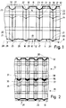
- the present exemplary embodiment relates to the handling of material webs 10 from blanks 11 for hinged boxes or hinge-lid packs for holding cigarettes.
- the elongated, approximately rectangular blanks 11 are oriented transversely within the material web.
- the blanks 11 for hinged boxes have a characteristic structure.
- An elongated center piece 12 consists at one end (edge of the material web 10) of a front wall 13 and opposite from a cover front wall 14 with a cover inner tab 15 arranged on the free edge thereof.
- the center piece 12 is - except in the area of the cover - Inner flap 15 - provided with side flaps.
- side flaps 16, 17 in the region of the front wall 13 and lid side flaps 18, 19 on the opposite side of the blank 11 are of interest.
- the side tabs 16 and 17 are delimited by outwardly projecting or projecting oblique edges 20, 21. Accordingly, the lid side tabs 18, 19 on the limited to the outside or laterally by recessed beveled edges 22, 23.
- the blanks 11 are provided with longitudinal and transverse punchings in the area of the side folding tabs.
- the blanks 11 are therefore almost completely finished. Only in a central area are the blanks 11 connected to one another via material webs 24 as residual connections to be separated, forming the material web 10.
- the special shape of the blanks 11 results in a material web 10 with special contours on the two longitudinal edges.
- the blanks 11 form trapezoidal depressions 25 which are delimited by triangular or tapered projections 26.
- a triangular depression 27 is formed between adjacent blanks 11 with limbs delimited by the inner lid lugs 15.
- conveying members are provided with projections which fit into the recesses 25 and 27 in a suitable and form-fitting manner.
- the material web 10 is transported on the circumference of a conveyor drum 28.
- This is provided on the one hand with trapezoidal elevations 29 and on the opposite with the recess 27 corresponding in shape and size to elevations 30.
- the elevations 29 form a continuous edge elevation 31 on one side of the conveyor drum 28. With the inside contour, this continuously delimits the material web 10 in the entire area of the system on the circumference of the conveyor drum 28.
- the material web 10 is between the elevations 29, 30, that is to say both sides of the conveyor drum 28, exactly positioned.
- the elevations 29, 30 enter and leave the depressions 25, 27 is lightened out and mechanical loads on the material web 10 are avoided, the elevations 29, 30 and also the edge elevation 31 in the areas facing the material web 10 are provided with oblique side surfaces 33, 34.
- the elevations in question converge towards the free outside, that is to say with a decreasing cross section.
- the conveyor for the material web 10, in particular the conveyor drum 28, can also be designed so that several, for. B. two material webs 10, 35 are transported side by side. If the blanks 11 within the two material webs 10, 35 are aligned, the edge of the conveying drum 28 results in the manner already described.
- form-fitting guiding or adjusting elements are arranged in the area between the material webs 10 and 35, that is to say in the middle of the conveying drum 28.
- these are guiding webs 36 which are V-shaped in cross section, that enter into a correspondingly designed, V-shaped recess 37 between the two material webs 10 and 35 in a form-fitting manner.
- the recess 37 results in the area of the inner lid lugs 15, delimited by the beveled edges 20..23.
- the two material webs 10, 35 are separated from one another in the longitudinal direction by a longitudinal cut 38.
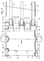
- the conveyor drum 28 need not be designed with a full cylindrical outer surface. As can be seen in particular from FIG. 3, the conveyor drum 28 can have grooves 39, 40, 41 running in the circumferential direction. Between these, support disks 42, 43 are formed in the central area, which are cylindrical and form corresponding contact surfaces for the material web 10.
- One groove 39 on the edge is delimited on the outside by a drum disk 32, on the cylindrical circumference of which the elevations 30 are arranged.
- the opposite groove 41 on the edge is delimited by the edge elevation 31.
- conveyor belts 44 and 45 enter the grooves 39..41 with their ends, namely with deflection rollers 46, and take over the material web 10, 35.
- strip-shaped, fixed deflectors 47 are in the region of the transition from the conveyor drum 28 to the conveyor belts 44, 45 arranged. The deflectors 47 enter the grooves 39..41 at one end.
- three adjacent conveyor belts 44 are provided for the removal of the material web 10, 35 in accordance with the number of grooves 39..41.
- the device described is particularly suitable for forming a zigzag-shaped formation 48 of the material web 10, 35.
- This formation 48 can serve as a material store, since a large supply of blanks 11 can be accommodated in a narrow space.
- the material web 10 forms kinks 49, 50 in the area between adjacent blanks 11, namely in the area of the remaining connections or material webs 24.
- the formation 48 is located between upper and lower parallel conveyor belts 44, 45.
- the kinks 49, 50 designed as folded edges support depend on the conveyor runs of the conveyor belts 44, 45 driven in the same direction. These are driven in accordance with the formation of the formation 48 on one side and the degradation thereof on the other side.
- the kinking takes place here with the aid of the conveyor drum 28 and an auxiliary drum 51 located opposite or above it. Both drums 28 and 51 lie close together in one area with the peripheral surfaces.
- the auxiliary drum 51 is designed analogously to the conveyor drum 28, namely likewise with grooves 39..41 and intermediate support disks 42, 43. The one arranged above the belts 44
- the auxiliary drum 51 is assigned to a group of three belts 45. Deflection rollers 46 extend partially in the area of the grooves 39..41.
- the material web 10 is fed via the (lower) conveyor drum 28.
- Both drums 28, 51 are provided with holding members for the material web 10, 35 distributed along the circumference, namely with suction members or suction bores 52, 53. These are distributed over the width (axial direction) of the drums 28, 51, such that at least two suction bores 52 on the one hand and 53 on the other hand lie side by side in a common radial plane of the drums (FIG. 3).
- the suction bores 52, 53 lie in the region of the support disks 42, 43.
- the suction bores 52 on the one hand and 53 on the other hand are each offset along the circumference of the drums and arranged at equal distances from one another, the distances being matched to the dimensions of the blanks 11 in the longitudinal direction of the material web 10. Furthermore, the suction bores 52 of the conveyor drum 28 are arranged offset on the other hand relative to the suction bores 53 of the auxiliary drum 51, namely exactly "on a gap". The relative position with respect to the material web 10 is selected so that a suction hole or group of suction holes 52, 53 is effective adjacent to an intended kink 49, 50 on one or the other side of the material web 10, 35.
- the suction bores 52, 53 are seen in the transport direction in each case on a front region of the blanks 11 - adjacent to the kink 49, 50 to be formed in the region of the material webs 24.
- the sequence in the formation of the kinks 49, 50 results from FIGS. 5 to 7.
- the material web 10 is transported in the position according to FIG. 5 on the circumference of the conveyor drum 28, with an area adjacent to the (lower) kink 50 to be formed of the subsequent blank 11 is held by suction bores 52.
- the subsequent one Part of the zigzag formation 48 is held with the kinks 49, 50 between the conveyor belts 44, 45.
- the kink 50 is now completed by further transport of the material web 10 between the conveyor belts 44, 45.
- the blank 11 following in the area of the material web 10 is gripped by a suction bore 53 of the auxiliary drum 51 located in the corresponding position.
- the material web is now conveyed with a partial area along the circumference of the auxiliary drum 51, a further, upper kink 49 being formed due to the fixation of the formation 48 (FIGS. 6 and 7).
- the area of the upper kink 49 is fed to the upper conveyor belts 45 by further rotation of the auxiliary drum 51 and is transferred there to the formation 48 which is conveyed further.
- This process of forming kinks 49, 50 and thus the formation of a zigzag formation 48 takes place continuously.
- the conveyor belts 44, 45 can also be moved continuously.
- the material web 10 is brought back into the stretched position and conveyed on.
- the formation 48 is laterally supported by guide rails 54 in the area between the conveyor belts 44, 45.
Landscapes
- Engineering & Computer Science (AREA)
- Mechanical Engineering (AREA)
- Making Paper Articles (AREA)
- Folding Of Thin Sheet-Like Materials, Special Discharging Devices, And Others (AREA)
- Registering, Tensioning, Guiding Webs, And Rollers Therefor (AREA)
- Preliminary Treatment Of Fibers (AREA)
Applications Claiming Priority (2)
| Application Number | Priority Date | Filing Date | Title |
|---|---|---|---|
| DE4234663 | 1992-10-15 | ||
| DE4234663A DE4234663A1 (de) | 1992-10-15 | 1992-10-15 | Vorrichtung zum Transport von bahnförmigem Verpackungsmaterial |
Publications (2)
| Publication Number | Publication Date |
|---|---|
| EP0592820A1 true EP0592820A1 (fr) | 1994-04-20 |
| EP0592820B1 EP0592820B1 (fr) | 1997-06-11 |
Family
ID=6470469
Family Applications (1)
| Application Number | Title | Priority Date | Filing Date |
|---|---|---|---|
| EP93114711A Expired - Lifetime EP0592820B1 (fr) | 1992-10-15 | 1993-09-14 | Dispositif pour le transport de matériel d'emballage en forme de bande |
Country Status (6)
| Country | Link |
|---|---|
| US (1) | US5447262A (fr) |
| EP (1) | EP0592820B1 (fr) |
| JP (1) | JP3341935B2 (fr) |
| BR (1) | BR9304233A (fr) |
| CA (1) | CA2106885A1 (fr) |
| DE (2) | DE4234663A1 (fr) |
Families Citing this family (8)
| Publication number | Priority date | Publication date | Assignee | Title |
|---|---|---|---|---|
| CN1071977C (zh) * | 1993-03-05 | 2001-09-26 | 杰姆斯达发展公司 | 使用压缩码作电视节目录像时间排定的装置与方法 |
| US5586964A (en) * | 1994-11-02 | 1996-12-24 | B. Bunch Company, Inc. | System for delivering folded paper |
| DE19726324A1 (de) * | 1997-06-20 | 1998-12-24 | Focke & Co | Verfahren und Vorrichtung zum Herstellen von Klappschachteln |
| GB2362637A (en) | 2000-05-24 | 2001-11-28 | Hewlett Packard Co | Grooved feed cylinder for use in printing on lenticular material |
| ITFI20040144A1 (it) * | 2004-06-25 | 2004-09-25 | Perini Fabio Spa | Macchina piegatrice con mezzi aspiranti per piegare un materiale nastriforme continuo e relativo metodo di piegatura |
| US8806533B1 (en) | 2004-10-08 | 2014-08-12 | United Video Properties, Inc. | System and method for using television information codes |
| JP5005184B2 (ja) * | 2005-04-27 | 2012-08-22 | サントリーホールディングス株式会社 | ラベル貼付装置 |
| IT201900007599A1 (it) * | 2019-05-30 | 2020-11-30 | Gd Spa | Dispositivo per raggruppare sbozzati di incarti di articoli da fumo |
Citations (5)
| Publication number | Priority date | Publication date | Assignee | Title |
|---|---|---|---|---|
| US3825139A (en) * | 1973-06-11 | 1974-07-23 | Koehring Co | Means for locking forklift truck forks in stored position |
| US4114355A (en) * | 1976-02-05 | 1978-09-19 | Molins Limited | Apparatus for the production of wrappers |
| US4625902A (en) * | 1983-02-10 | 1986-12-02 | Tetra Pak International Ab | Method and arrangement for the feeding of a material web |
| US4898569A (en) * | 1987-05-20 | 1990-02-06 | Focke & Co. (Gmbh & Co.) | Process, web of material and apparatus for producing packaging blanks |
| DE4039133A1 (de) * | 1989-12-07 | 1991-06-13 | Gd Spa | Verfahren zum befoerdern und falten von bogenmaterial in einer verpackungsmaschine |
Family Cites Families (13)
| Publication number | Priority date | Publication date | Assignee | Title |
|---|---|---|---|---|
| DE547168C (de) * | 1930-05-06 | 1932-03-23 | Sapal Plieuses Automatiques | Einrichtung zum Zufuehren von Wellpappe an die Verarbeitungsstelle in Verpackungsmaschinen |
| CH346474A (de) * | 1955-08-06 | 1960-05-15 | Heinrich Hermann Fa | Von einer Vorratsrolle abziehbarer bandförmiger Klammerstreifen mit zugehöriger Vorschubeinrichtung |
| DE1223854B (de) * | 1956-09-26 | 1966-09-01 | Andreas Vilhelm Borch Madsen D | Mehrfarbenrotationsdruckmaschine zum Bedrucken perforierter, mittels Stiftwalzen gefoerderter Bahnen |
| DE1177464B (de) * | 1962-07-23 | 1964-09-03 | James Bowen Fulk | Verfahren und Anordnung zum fortlaufenden Bearbeiten von fuer Formularsaetze bestimmten Papierbahnen |
| US4070014A (en) * | 1975-07-28 | 1978-01-24 | Kawanoe Zoki Kabushiki Kaisha | Web folding apparatus |
| US4834276A (en) * | 1983-08-05 | 1989-05-30 | Gerber Scientific Products, Inc. | Web loading and feeding system, related web construction and method and apparatus for making web |
| DE3735674A1 (de) * | 1987-10-22 | 1989-05-03 | Focke & Co | Vorrichtung zum herstellen von (zigaretten-)packungen |
| DE3832533A1 (de) * | 1988-09-24 | 1990-03-29 | Focke & Co | Vorrichtung zum zufuehren von verpackungs-zuschnitten zu einem faltaggregat |
| US4981374A (en) * | 1988-09-30 | 1991-01-01 | Rapak, Inc. | Plastic bags carried in a continuous web |
| DE3910986A1 (de) * | 1989-04-05 | 1990-10-11 | Focke & Co | Verfahren und vorrichtung zum herstellen von (zigaretten -) packungen |
| DE3923778A1 (de) * | 1989-07-18 | 1991-01-31 | Windmoeller & Hoelscher | Vorrichtung zum transportieren einer vorzugsweise mehrlagigen bahn aus thermoplastischem kunststoff |
| DE4003192A1 (de) * | 1990-02-03 | 1991-08-08 | Focke & Co | Verfahren und vorrichtung zur zufuehrung einer materialbahn zu einer ver- bzw. bearbeitungsmaschine, insbesondere verpackungsmaschine |
| DE4003451A1 (de) * | 1990-02-06 | 1991-08-08 | Focke & Co | Verfahren und vorrichtung zum handhaben, insbesondere foerdern von zuschnitten |
-
1992
- 1992-10-15 DE DE4234663A patent/DE4234663A1/de not_active Withdrawn
-
1993
- 1993-09-14 DE DE59306729T patent/DE59306729D1/de not_active Expired - Fee Related
- 1993-09-14 EP EP93114711A patent/EP0592820B1/fr not_active Expired - Lifetime
- 1993-09-24 CA CA002106885A patent/CA2106885A1/fr not_active Abandoned
- 1993-09-30 US US08/128,962 patent/US5447262A/en not_active Expired - Fee Related
- 1993-10-14 BR BR9304233A patent/BR9304233A/pt not_active IP Right Cessation
- 1993-10-15 JP JP25869493A patent/JP3341935B2/ja not_active Expired - Fee Related
Patent Citations (5)
| Publication number | Priority date | Publication date | Assignee | Title |
|---|---|---|---|---|
| US3825139A (en) * | 1973-06-11 | 1974-07-23 | Koehring Co | Means for locking forklift truck forks in stored position |
| US4114355A (en) * | 1976-02-05 | 1978-09-19 | Molins Limited | Apparatus for the production of wrappers |
| US4625902A (en) * | 1983-02-10 | 1986-12-02 | Tetra Pak International Ab | Method and arrangement for the feeding of a material web |
| US4898569A (en) * | 1987-05-20 | 1990-02-06 | Focke & Co. (Gmbh & Co.) | Process, web of material and apparatus for producing packaging blanks |
| DE4039133A1 (de) * | 1989-12-07 | 1991-06-13 | Gd Spa | Verfahren zum befoerdern und falten von bogenmaterial in einer verpackungsmaschine |
Also Published As
| Publication number | Publication date |
|---|---|
| CA2106885A1 (fr) | 1994-04-16 |
| US5447262A (en) | 1995-09-05 |
| DE4234663A1 (de) | 1994-04-21 |
| EP0592820B1 (fr) | 1997-06-11 |
| DE59306729D1 (de) | 1997-07-17 |
| JPH06234464A (ja) | 1994-08-23 |
| JP3341935B2 (ja) | 2002-11-05 |
| BR9304233A (pt) | 1994-04-19 |
Similar Documents
| Publication | Publication Date | Title |
|---|---|---|
| EP0071736B2 (fr) | Dispositif d'emballage pour la fabrication de découpes et pour amener celles-ci à une station d'emballage | |
| EP0444547B1 (fr) | Méthode et dispositif pour convoyer des bandes de fermeture en vue de les transférer à des paquets | |
| EP0399264A1 (fr) | Procédé et dispositif pour changer la position relative de paquets, en particulier de paquets de cigarettes parallélépipédiques du type à couvercle articulé (hinge-lid) | |
| DE3106155C2 (fr) | ||
| EP0600328A1 (fr) | Procédé et dispositif de réception et de transfert de matière en feuille | |
| EP0514951A1 (fr) | Procédé et dispositif pour fabriquer et transporter des découpes d'emballage | |
| DE2660035C2 (de) | Vorrichtung zum Abstreifen von gestanzten Abschnitten oder Ausschnitten aus Wellpappe- oder Kartonzuschnitten | |
| EP0667231B1 (fr) | Appareil pour former des flancs pour boîtes à charnière avec des arêtes longitudinales arrondies | |
| EP0550406A1 (fr) | Procédé et dispositif pour la fabrication d'emballages (pour cigarettes) | |
| EP0592820A1 (fr) | Dispositif pour le transport de matériel d'emballage en forme de bande | |
| DE4237937C2 (de) | Vorrichtung zum Transport von Zuschnittstapeln | |
| DE69502310T2 (de) | Förderanlage für Gruppen von empfindlichen, länglichen Gegenständen, insbesondere in Zigarettenverpackungsmaschinen | |
| EP0667232A1 (fr) | Appareil pour la production de flancs de collets pour boîtes à charnière avec des arêtes longitudinales arrondies | |
| DE3119016C2 (fr) | ||
| DE2417722A1 (de) | Vorrichtung zur herstellung eines gefalteten kartons | |
| DE1131979B (de) | Stapelvorrichtung fuer bogenfoermiges Material | |
| DE69411908T2 (de) | Vorrichtung zum verpacken in faltschachteln | |
| EP1048229A2 (fr) | Appareil et méthode pour fabriquer des cigarettes | |
| DE4220026A1 (de) | Verfahren und Vorrichtung zum Abräumen von Zuschnittstapeln von einer Palette oder dergleichen | |
| DE4100783C2 (fr) | ||
| DE102021127421A1 (de) | Transporteinrichtung | |
| EP0562432B1 (fr) | Procédé et dispositif pour le déchargement de paquets de feuilles d'une palette ou analogue | |
| DE3602206A1 (de) | Backautomat | |
| DE2921772A1 (de) | Behaeltertransportvorrichtung | |
| DE4308659A1 (de) | Verfahren und Vorrichtung zur Herstellung von Zigarettenstangen |
Legal Events
| Date | Code | Title | Description |
|---|---|---|---|
| PUAI | Public reference made under article 153(3) epc to a published international application that has entered the european phase |
Free format text: ORIGINAL CODE: 0009012 |
|
| AK | Designated contracting states |
Kind code of ref document: A1 Designated state(s): DE FR GB IT |
|
| 17P | Request for examination filed |
Effective date: 19941019 |
|
| 17Q | First examination report despatched |
Effective date: 19950926 |
|
| GRAG | Despatch of communication of intention to grant |
Free format text: ORIGINAL CODE: EPIDOS AGRA |
|
| GRAH | Despatch of communication of intention to grant a patent |
Free format text: ORIGINAL CODE: EPIDOS IGRA |
|
| GRAH | Despatch of communication of intention to grant a patent |
Free format text: ORIGINAL CODE: EPIDOS IGRA |
|
| GRAA | (expected) grant |
Free format text: ORIGINAL CODE: 0009210 |
|
| AK | Designated contracting states |
Kind code of ref document: B1 Designated state(s): DE FR GB IT |
|
| GBT | Gb: translation of ep patent filed (gb section 77(6)(a)/1977) |
Effective date: 19970612 |
|
| REF | Corresponds to: |
Ref document number: 59306729 Country of ref document: DE Date of ref document: 19970717 |
|
| ITF | It: translation for a ep patent filed | ||
| ET | Fr: translation filed | ||
| PLBE | No opposition filed within time limit |
Free format text: ORIGINAL CODE: 0009261 |
|
| 26N | No opposition filed | ||
| REG | Reference to a national code |
Ref country code: GB Ref legal event code: IF02 |
|
| PGFP | Annual fee paid to national office [announced via postgrant information from national office to epo] |
Ref country code: FR Payment date: 20040908 Year of fee payment: 12 |
|
| PG25 | Lapsed in a contracting state [announced via postgrant information from national office to epo] |
Ref country code: FR Free format text: LAPSE BECAUSE OF NON-PAYMENT OF DUE FEES Effective date: 20060531 |
|
| REG | Reference to a national code |
Ref country code: FR Ref legal event code: ST Effective date: 20060531 |
|
| PGFP | Annual fee paid to national office [announced via postgrant information from national office to epo] |
Ref country code: GB Payment date: 20060913 Year of fee payment: 14 |
|
| PGFP | Annual fee paid to national office [announced via postgrant information from national office to epo] |
Ref country code: DE Payment date: 20060926 Year of fee payment: 14 |
|
| PGFP | Annual fee paid to national office [announced via postgrant information from national office to epo] |
Ref country code: IT Payment date: 20060930 Year of fee payment: 14 |
|
| GBPC | Gb: european patent ceased through non-payment of renewal fee |
Effective date: 20070914 |
|
| PG25 | Lapsed in a contracting state [announced via postgrant information from national office to epo] |
Ref country code: DE Free format text: LAPSE BECAUSE OF NON-PAYMENT OF DUE FEES Effective date: 20080401 |
|
| PG25 | Lapsed in a contracting state [announced via postgrant information from national office to epo] |
Ref country code: GB Free format text: LAPSE BECAUSE OF NON-PAYMENT OF DUE FEES Effective date: 20070914 |
|
| PG25 | Lapsed in a contracting state [announced via postgrant information from national office to epo] |
Ref country code: IT Free format text: LAPSE BECAUSE OF NON-PAYMENT OF DUE FEES Effective date: 20070914 |