EP0592854A1 - Dispositif de montage d'une poignée de porte amovible - Google Patents
Dispositif de montage d'une poignée de porte amovible Download PDFInfo
- Publication number
- EP0592854A1 EP0592854A1 EP93115527A EP93115527A EP0592854A1 EP 0592854 A1 EP0592854 A1 EP 0592854A1 EP 93115527 A EP93115527 A EP 93115527A EP 93115527 A EP93115527 A EP 93115527A EP 0592854 A1 EP0592854 A1 EP 0592854A1
- Authority
- EP
- European Patent Office
- Prior art keywords
- door handle
- spring
- detachable
- mandrel
- connection according
- Prior art date
- Legal status (The legal status is an assumption and is not a legal conclusion. Google has not performed a legal analysis and makes no representation as to the accuracy of the status listed.)
- Granted
Links
- 229910000639 Spring steel Inorganic materials 0.000 claims description 4
- 239000011324 bead Substances 0.000 claims 1
- 238000004519 manufacturing process Methods 0.000 abstract description 4
- 235000004789 Rosa xanthina Nutrition 0.000 abstract 1
- 241000109329 Rosa xanthina Species 0.000 abstract 1
- 210000003746 feather Anatomy 0.000 description 2
- 238000009434 installation Methods 0.000 description 2
- 240000003517 Elaeocarpus dentatus Species 0.000 description 1
- 241001295925 Gegenes Species 0.000 description 1
- 230000006978 adaptation Effects 0.000 description 1
- 230000004888 barrier function Effects 0.000 description 1
- 230000005540 biological transmission Effects 0.000 description 1
- 238000005266 casting Methods 0.000 description 1
- 238000010276 construction Methods 0.000 description 1
- 238000005516 engineering process Methods 0.000 description 1
- 230000002349 favourable effect Effects 0.000 description 1
- 238000007654 immersion Methods 0.000 description 1
- 238000003780 insertion Methods 0.000 description 1
- 230000037431 insertion Effects 0.000 description 1
- 238000007726 management method Methods 0.000 description 1
- 238000012986 modification Methods 0.000 description 1
- 230000004048 modification Effects 0.000 description 1
- 230000002940 repellent Effects 0.000 description 1
- 239000005871 repellent Substances 0.000 description 1
- 210000002023 somite Anatomy 0.000 description 1
Images



Classifications
-
- E—FIXED CONSTRUCTIONS
- E05—LOCKS; KEYS; WINDOW OR DOOR FITTINGS; SAFES
- E05B—LOCKS; ACCESSORIES THEREFOR; HANDCUFFS
- E05B3/00—Fastening knobs or handles to lock or latch parts
- E05B3/04—Fastening the knob or the handle shank to the spindle by screws, springs or snap bolts
-
- E—FIXED CONSTRUCTIONS
- E05—LOCKS; KEYS; WINDOW OR DOOR FITTINGS; SAFES
- E05B—LOCKS; ACCESSORIES THEREFOR; HANDCUFFS
- E05B63/00—Locks or fastenings with special structural characteristics
- E05B63/0056—Locks with adjustable or exchangeable lock parts
- E05B63/006—Locks with adjustable or exchangeable lock parts for different door thicknesses
Definitions
- the invention relates to a detachable door handle connection which can be adjusted to any door thickness.
- the door handle set is usually connected to an angular door handle mandrel, which is designed square and penetrates the lock groove.
- the angular door handle mandrel is serrated on at least one side surface, a groove running parallel to the handle hole being present in the toothed side surface of the door handle mandrel opposite, in which a retaining spring is arranged.
- This retaining spring is in direct engagement with the toothed side surfaces of the lever handle mandrel. This ensures that in cooperation with the teeth when the door handle mandrel penetrates into the hole, the door handle creates a connection such that the handle is secured against slipping out.
- the positive entrainment of the door handle mandrel ensures that when one handle is actuated, the other inevitably moves as well.
- a detachable handle connection that can be adjusted to any door thickness has become known from the German designation 20 01 636.
- a leaf spring is U-shaped, and at the same time an eye is formed in the rear area of the spring, through which a retaining screw is inserted from the end face of the pusher.
- this connection has the disadvantage that the cross screw of the door handle mandrel has only a small immersion depth in the door handle and a fluttering and wobbling free torque transmission for the door handle mandrel is extremely difficult to manufacture due to the recess in the spring chamber up to the door handle hole end. This also applies to the type of connection, which can be found in German utility model 78 36 758.
- the German designation 11 17 442 shows a tongue-shaped leaf spring, which is attached to the side of a pusher pin designed as a square pin in the pusher neck by a grub screw.
- the inward end of the leaf spring engages as a locking tongue in the Gearing of the square pin.
- this type of fastening has the disadvantage that the groove of the pusher neck is undercut and the leaf spring must be guided in it with a central piece that is widened relative to the end parts and must be pressed against the upper limit of the undercut of the groove by the retaining screw.
- the production of this undercut groove is extremely difficult and very costly in terms of casting technology.
- the recess for the undercut groove in the door handle guide approach has such a large space requirement that the spring chamber would be opened and thus damaged when radial grooves were inserted for rotatable connections on door plates and door closets.
- a complex lever handle connection can be found in German utility model 74 25 072.
- the lever handle mandrel can be inserted via an insert bush, which is secured by cross-pinning or screwing. This connection is also not suitable for receiving a recess for an undercut groove in the door handle guide attachment.
- the object of the invention is to provide a detachable door handle connection with simple means, in which the retaining spring is not lost when removed, but at the same time the adjustability to any door thickness with play-free assembly must be possible, with a functionally favorable attachment of the retaining spring without an undercut groove and without an annoying cross screw, as well as the damage-free production of radial grooves on the door handle guide attachment for clipping tightly rotatable bearing systems on door plates and rosettes is guaranteed.
- the object of the invention is achieved in that a retaining spring with a U-shaped design is used, in which there are two repellent spring legs which converge in a base which has an opening for the door handle mandrel in its central region. These spring legs are directed outwards under pretension and have bulges which are supported on the one hand against the door handle mandrel and on the other hand against the side surfaces of a groove made within the handle set.
- the retaining spring is held by a securing element, which is advantageously introduced on the side facing away from the user, i.e. towards the floor.
- In the end region of the spring legs there is at least one angled spring end which engages with the toothing of the door handle mandrel.
- the retaining spring on both spring legs must also have a latching edge so that a secure latching with the door handle mandrel is ensured in the inserted state.
- a two-sided screwing of the retaining spring is of course also possible.
- the lever handle can be provided with the retaining spring before delivery. This enables quick assembly at the construction site, so that only the door handle mandrel has to be inserted. If the door handle mandrel is inserted, there is a permanent connection between the door handle and the door handle mandrel. Only by loosening at least one retaining screw can the release of the door handle be made possible, which then looks so that when the door handle is removed, the retaining spring remains on the door handle mandrel. This has the advantage that when the door handles and the door handle mandrel are subsequently reassembled, they are not annoying Setting the door widths is necessary.
- the securing element ie the retaining screw
- the retaining screw which can be a cylinder screw with a pin or with an annular cutting edge. While the normal retaining screw is supported in the door handle neck and has no contact with the door handle mandrel, and thus only exerts a holding function for the retaining spring, when using a securing element, for example a threaded pin with a pin and a ring washer, a non-positive and positive connection between the Door handle and the door handle mandrel manufactured.
- the retaining spring can be made of spring steel with a surface protection, but it is also possible to use this retaining spring made of stainless spring steel in particularly aggressive atmospheres.
- the door handle mandrel (6) If the door handle mandrel (6) is now inserted into the pre-assembled handle half, for example (20) with the retaining spring (24), it supports already on insertion of the bulges (16) of the retaining spring (24). This enables the door handle mandrel (6) to be inserted without play. If the door handle mandrel end comes over the end of the spring legs (1) and (2), the toothing (19) located on the door handle mandrel (6) comes together with the latching edge (28), and pulling out the door handle mandrel is not due to the undercut toothing more is possible. Only when the securing element (10) is removed can the holding spring (24) be removed from the handle neck (12) with the door handle mandrel. The fine-toothed toothing (19) ensures that adaptation to different door thicknesses is possible
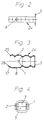
- FIGs 2, 3 and 4 show the special design of the retaining spring (24) used according to the invention.
- the retaining spring (24) consists essentially of two spring legs (1) and (2) which are brought together in a U-shape over a base (3). Inside the base (3) there is an opening (5) through which the door handle mandrel (6) is guided.
- the spring legs (1) and (2) are under a certain pretension, ie they are spread outwards so that they give the holding spring (24) a certain hold when inserted into the lever handle hole (21).
- the spring legs (1) and (2) are designed so that bulges (16) are present, which in turn assume a management and spring function when the lever handle mandrel (6) is inserted through the opening (5) in the installed state.
- the door handle mandrel (6) is then supported against the bulges (16) without play.
- locking edges (28) are attached at the spring ends (17) and (25) with one-sided toothing of the door handle mandrel (6).
- These locking edges (28) in the end region of the spring ends (17) and (25) have the task of preventing the door handle mandrel from coming out in the inserted state, as long as the retaining spring (24) is connected to the handle via the retaining barrier (10), because the Locking edge (28) engages in the toothing (19) of the lever handle mandrel (6).
- the retaining spring (24) cannot fall out of the lever handle hole (21), it is held by means of a securing element (10) which, with its attachment, passes through the retaining hole (8).
- the retaining hole (8) is located within a spring leg (1) or (2) and thus secures the retaining spring (24) against falling out.
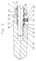
- FIG. 5 shows in a sectional drawing how the door handle mandrel (6) assumes a secure positioning within the handle neck (12). It is clear that only in the front area, i.e. In the door handle guide extension (23), it is necessary to hold the retaining spring (24), because in its end area the door handle mandrel (6) is guided in the door handle hole end (26) of the same geometric design in a non-positive and positive manner. So that the retaining spring (24) receives a defined fit, it is held within the spring chamber (22). It is supported on the one hand against the groove wall (7) of the spring chamber (22) and on the other hand with its bulges (16) against the door handle mandrel (6).
- the holding spring (24) is in turn supported with its base (3) against the end face (4) of the lever handle guide attachment (23).
- a radial groove (18) can be introduced into the door handle guide attachment (23) without damaging the groove wall (7), in which rosettes, for example, can be clipped in place.
- the invention also includes modifications that are not shown, for example in such a way that the door handle mandrel (6) is anchored in one of the two door handle halves (20) and (29), for example by a pinning or cohesively, while in the other door handle half (20) or ( 29) a detachable connection is provided with the aid of the holding spring (24) shown.
- FIGS 7 and 8 show again in detail the fastening of the retaining spring (24) within the lever handle neck (12).
- a cylinder head screw (13) can be used as a securing element of the retaining spring (24).
- This cylinder head screw (13) has in its end region a pin (9) which passes through the holding hole (8) of the holding spring (24) and thus secures the holding spring (24) against falling out.
- the cylinder head screw (13) in turn is supported on a stop (32) within the lever handle neck (12).
- a setscrew (14) is used instead of the cylinder head screw, it also has a pin (27) which passes through the holding hole (8) Retaining spring (24) passes through.
- annular cutting edge (15) can also be connected to the pin (27).
- the pin (27) first holds the retaining spring (24) in the axial direction, and after the latching assembly of the door handle mandrel (6), this setscrew (14) with its ring cutting edge (15) can also be screwed into the toothing (19). This represents an additional safeguard for the door handle mandrel (6).
- FIG. 9 Another variant is shown in FIG. 9, where the retaining spring (24) is held on the one hand with countersunk head screws (11) on both sides of the spring legs (1) and (2).
- the cylinder countersunk screw (11) is screwed through the holding bore (8) of the holding spring (24), as in the manner already described, and thus secures the holding spring (24) against unintentional slipping out.
Landscapes
- Engineering & Computer Science (AREA)
- Mechanical Engineering (AREA)
- Lock And Its Accessories (AREA)
Applications Claiming Priority (2)
| Application Number | Priority Date | Filing Date | Title |
|---|---|---|---|
| DE4234870A DE4234870C1 (de) | 1992-10-16 | 1992-10-16 | Lösbare Türdrückerverbindung |
| DE4234870 | 1992-10-16 |
Publications (2)
| Publication Number | Publication Date |
|---|---|
| EP0592854A1 true EP0592854A1 (fr) | 1994-04-20 |
| EP0592854B1 EP0592854B1 (fr) | 1995-12-06 |
Family
ID=6470594
Family Applications (1)
| Application Number | Title | Priority Date | Filing Date |
|---|---|---|---|
| EP93115527A Expired - Lifetime EP0592854B1 (fr) | 1992-10-16 | 1993-09-25 | Dispositif de montage d'une poignée de porte amovible |
Country Status (3)
| Country | Link |
|---|---|
| EP (1) | EP0592854B1 (fr) |
| AT (1) | ATE131246T1 (fr) |
| DE (1) | DE4234870C1 (fr) |
Cited By (3)
| Publication number | Priority date | Publication date | Assignee | Title |
|---|---|---|---|---|
| FR2750444A1 (fr) * | 1996-07-01 | 1998-01-02 | Dubois Ind Sa | Accouplement du carre a ses organes de manoeuvre dans une poignee de porte, et poignee de porte en faisant application |
| EP2172606B2 (fr) † | 2008-10-06 | 2019-04-03 | Burg-Wächter Kg | Dispositif de poignée |
| US12352074B2 (en) | 2019-09-11 | 2025-07-08 | Honeywell International Inc. | Hub assembly for door handle |
Families Citing this family (3)
| Publication number | Priority date | Publication date | Assignee | Title |
|---|---|---|---|---|
| DE10353120B4 (de) * | 2003-11-12 | 2005-11-10 | Dorma Gmbh + Co. Kg | Türdrückerklemmbefestigung |
| DE102016113990A1 (de) * | 2016-07-28 | 2018-02-01 | Hafi Beschläge GmbH | Fenstergriffbeschlag |
| CN108252571A (zh) * | 2018-03-08 | 2018-07-06 | 陈宏宾 | 一种带有自锁扣件固定且方便拆卸的快装把手 |
Citations (7)
| Publication number | Priority date | Publication date | Assignee | Title |
|---|---|---|---|---|
| DE309081C (fr) * | ||||
| GB376100A (en) * | 1931-09-28 | 1932-07-07 | Richard Cartwright | Improvements in and relating to door knobs and the like |
| US3345103A (en) * | 1965-01-21 | 1967-10-03 | United Carr Inc | Handle assemblies and means for detachably securing a handle to a rod-like element |
| DE1258758B (de) * | 1965-12-20 | 1968-01-11 | Hugo Haussels Fa | Loesbare, auf beliebige Tuerdicke einstellbare Tuerdrueckerklemmbefestigung |
| FR1528454A (fr) * | 1966-06-23 | 1968-06-07 | Grossteinbeck Gmbh Otto | Dispositif de fixation de poignée de porte |
| DE1930679A1 (de) * | 1969-06-18 | 1971-01-07 | Hugo Haussels Fa | Loesbare,auf beliebige Tuerdicke einstellbare Tuerdrueckerklemmbefestigung |
| DE4024614A1 (de) * | 1990-08-02 | 1992-02-06 | Goldschmidt Baubeschlaege | Fenster- oder tuerbeschlag |
Family Cites Families (6)
| Publication number | Priority date | Publication date | Assignee | Title |
|---|---|---|---|---|
| DE7425072U (de) * | 1975-01-02 | Hoppe F Kg Baubeschlagfabriken | Türdrückerverbindung | |
| US2528675A (en) * | 1947-01-20 | 1950-11-07 | Tinnerman Products Inc | Fastening device |
| DE1117442B (de) * | 1959-09-25 | 1961-11-16 | Otto Grosssteinbeck G M B H | Tuerdrueckerverbindung |
| DE1912974C3 (de) * | 1969-03-14 | 1975-06-26 | Westfaelisches Metallwerk Franz Schneider, 3492 Brakel | Türdrücker-Dornverbindung mit Rastverzahnung |
| DE2001636C3 (de) * | 1970-01-15 | 1973-12-20 | Otto 5620 Velbert Knittel | Lösbare, auf beliebige Türstärke einstellbare Türdrückerverbindung |
| DE7836758U1 (de) * | 1978-12-12 | 1979-03-29 | Otto Grossteinbeck Gmbh, 5620 Velbert | Loesbare, einstellbare tuerdrueckerverbindung |
-
1992
- 1992-10-16 DE DE4234870A patent/DE4234870C1/de not_active Expired - Fee Related
-
1993
- 1993-09-25 EP EP93115527A patent/EP0592854B1/fr not_active Expired - Lifetime
- 1993-09-25 AT AT93115527T patent/ATE131246T1/de not_active IP Right Cessation
Patent Citations (7)
| Publication number | Priority date | Publication date | Assignee | Title |
|---|---|---|---|---|
| DE309081C (fr) * | ||||
| GB376100A (en) * | 1931-09-28 | 1932-07-07 | Richard Cartwright | Improvements in and relating to door knobs and the like |
| US3345103A (en) * | 1965-01-21 | 1967-10-03 | United Carr Inc | Handle assemblies and means for detachably securing a handle to a rod-like element |
| DE1258758B (de) * | 1965-12-20 | 1968-01-11 | Hugo Haussels Fa | Loesbare, auf beliebige Tuerdicke einstellbare Tuerdrueckerklemmbefestigung |
| FR1528454A (fr) * | 1966-06-23 | 1968-06-07 | Grossteinbeck Gmbh Otto | Dispositif de fixation de poignée de porte |
| DE1930679A1 (de) * | 1969-06-18 | 1971-01-07 | Hugo Haussels Fa | Loesbare,auf beliebige Tuerdicke einstellbare Tuerdrueckerklemmbefestigung |
| DE4024614A1 (de) * | 1990-08-02 | 1992-02-06 | Goldschmidt Baubeschlaege | Fenster- oder tuerbeschlag |
Cited By (3)
| Publication number | Priority date | Publication date | Assignee | Title |
|---|---|---|---|---|
| FR2750444A1 (fr) * | 1996-07-01 | 1998-01-02 | Dubois Ind Sa | Accouplement du carre a ses organes de manoeuvre dans une poignee de porte, et poignee de porte en faisant application |
| EP2172606B2 (fr) † | 2008-10-06 | 2019-04-03 | Burg-Wächter Kg | Dispositif de poignée |
| US12352074B2 (en) | 2019-09-11 | 2025-07-08 | Honeywell International Inc. | Hub assembly for door handle |
Also Published As
| Publication number | Publication date |
|---|---|
| ATE131246T1 (de) | 1995-12-15 |
| EP0592854B1 (fr) | 1995-12-06 |
| DE4234870C1 (de) | 1993-11-25 |
Similar Documents
| Publication | Publication Date | Title |
|---|---|---|
| DE2614446A1 (de) | Scharnier | |
| EP2105556A1 (fr) | Dispositif de verrouillage | |
| EP2366851A2 (fr) | Agencement de rosaces pour une porte | |
| EP1072745B1 (fr) | Ferrure de verrouillage pour fenêtres ou portes | |
| DE69805903T2 (de) | Beschlag mit einstellbarem Riegel für Schiebeflügel | |
| EP0592854B1 (fr) | Dispositif de montage d'une poignée de porte amovible | |
| EP2113624B1 (fr) | Dispositif de fixation de porte ou de fenêtre | |
| DE202004001068U1 (de) | Durch Einklipsen montierbares Laufwerkgehäuse für Schiebe- und Faltschiebetüren | |
| DE69207744T2 (de) | Betätigungshandhabe eines Fallenschlosses | |
| DE4024614A1 (de) | Fenster- oder tuerbeschlag | |
| DE202016101091U1 (de) | Türverriegelung | |
| DE69618315T2 (de) | Abnehmbarer Griff für Türen oder Fenster insbesondere in Metallprofilen | |
| EP3372764B1 (fr) | Dispositif de sécurisation | |
| EP2172606A2 (fr) | Dispositif de poignée | |
| DE29708489U1 (de) | Verriegelbare Betätigungsvorrichtung für Beschläge von Fenstern, Türen o.dgl. | |
| WO2010003435A1 (fr) | Système de bande | |
| DE4225971C2 (de) | Abstützvorrichtung zwischen Getriebegehäuse eines Einsteck-Kantengetriebes und einer damit über Ankerschrauben verbindbaren Lagerrosette eines Bedienungshebels | |
| EP2372051A2 (fr) | Ensemble de poignée | |
| DE29800735U1 (de) | Betätigungshandhabe | |
| DE2343933A1 (de) | Distanzhalter zwischen dem getriebegehaeuse eines einsteck-kantengetriebes und einer damit ueber ankerschrauben verbindbaren lagerrosette eines bedienungshebels | |
| EP1386050B1 (fr) | Element de retenue destine a retenir un rail de guidage pour portes coulissantes | |
| EP1344478A1 (fr) | Cabine de douche avec au moins une cloison de verre | |
| DE20219174U1 (de) | Dichtung insbesondere selbsttätig absenkende Bodendichtung für Türen | |
| DE69800142T2 (de) | Beschlag für Tür, Fenster o. dgl | |
| DE102017202727B4 (de) | Verdeckt angeordneter Beschlag für Fenster, Türen oder dergleichen |
Legal Events
| Date | Code | Title | Description |
|---|---|---|---|
| PUAI | Public reference made under article 153(3) epc to a published international application that has entered the european phase |
Free format text: ORIGINAL CODE: 0009012 |
|
| ITCL | It: translation for ep claims filed |
Representative=s name: DE DOMINICIS & MAYER S.R.L. |
|
| AK | Designated contracting states |
Kind code of ref document: A1 Designated state(s): AT CH FR GB IT LI |
|
| GBC | Gb: translation of claims filed (gb section 78(7)/1977) | ||
| EL | Fr: translation of claims filed | ||
| 17P | Request for examination filed |
Effective date: 19940607 |
|
| 17Q | First examination report despatched |
Effective date: 19941108 |
|
| ITF | It: translation for a ep patent filed | ||
| GRAA | (expected) grant |
Free format text: ORIGINAL CODE: 0009210 |
|
| AK | Designated contracting states |
Kind code of ref document: B1 Designated state(s): AT CH FR GB IT LI |
|
| REF | Corresponds to: |
Ref document number: 131246 Country of ref document: AT Date of ref document: 19951215 Kind code of ref document: T |
|
| ET | Fr: translation filed | ||
| GBT | Gb: translation of ep patent filed (gb section 77(6)(a)/1977) |
Effective date: 19951207 |
|
| REG | Reference to a national code |
Ref country code: CH Ref legal event code: NV Representative=s name: BOVARD AG PATENTANWAELTE |
|
| PLBE | No opposition filed within time limit |
Free format text: ORIGINAL CODE: 0009261 |
|
| STAA | Information on the status of an ep patent application or granted ep patent |
Free format text: STATUS: NO OPPOSITION FILED WITHIN TIME LIMIT |
|
| 26N | No opposition filed | ||
| REG | Reference to a national code |
Ref country code: GB Ref legal event code: IF02 |
|
| PG25 | Lapsed in a contracting state [announced via postgrant information from national office to epo] |
Ref country code: IT Free format text: LAPSE BECAUSE OF NON-PAYMENT OF DUE FEES;WARNING: LAPSES OF ITALIAN PATENTS WITH EFFECTIVE DATE BEFORE 2007 MAY HAVE OCCURRED AT ANY TIME BEFORE 2007. THE CORRECT EFFECTIVE DATE MAY BE DIFFERENT FROM THE ONE RECORDED. Effective date: 20050925 |
|
| PGFP | Annual fee paid to national office [announced via postgrant information from national office to epo] |
Ref country code: GB Payment date: 20090922 Year of fee payment: 17 Ref country code: CH Payment date: 20090923 Year of fee payment: 17 Ref country code: AT Payment date: 20090916 Year of fee payment: 17 |
|
| REG | Reference to a national code |
Ref country code: CH Ref legal event code: PFA Owner name: DORMA GMBH + CO. KG Free format text: DORMA GMBH + CO. KG#BRECKERFELDER STRASSE 42-48#D-58256 ENNEPETAL (DE) -TRANSFER TO- DORMA GMBH + CO. KG#BRECKERFELDER STRASSE 42-48#D-58256 ENNEPETAL (DE) |
|
| REG | Reference to a national code |
Ref country code: CH Ref legal event code: PL |
|
| GBPC | Gb: european patent ceased through non-payment of renewal fee |
Effective date: 20100925 |
|
| REG | Reference to a national code |
Ref country code: FR Ref legal event code: ST Effective date: 20110531 |
|
| PG25 | Lapsed in a contracting state [announced via postgrant information from national office to epo] |
Ref country code: LI Free format text: LAPSE BECAUSE OF NON-PAYMENT OF DUE FEES Effective date: 20100930 Ref country code: FR Free format text: LAPSE BECAUSE OF NON-PAYMENT OF DUE FEES Effective date: 20100930 Ref country code: CH Free format text: LAPSE BECAUSE OF NON-PAYMENT OF DUE FEES Effective date: 20100930 |
|
| PG25 | Lapsed in a contracting state [announced via postgrant information from national office to epo] |
Ref country code: AT Free format text: LAPSE BECAUSE OF NON-PAYMENT OF DUE FEES Effective date: 20100925 Ref country code: GB Free format text: LAPSE BECAUSE OF NON-PAYMENT OF DUE FEES Effective date: 20100925 |
|
| PGFP | Annual fee paid to national office [announced via postgrant information from national office to epo] |
Ref country code: FR Payment date: 20091001 Year of fee payment: 17 |