EP0592967B1 - Système et procédé d'imagerie ultrasonore de tissus, avec traitement Doppler en vitesse et accélération - Google Patents
Système et procédé d'imagerie ultrasonore de tissus, avec traitement Doppler en vitesse et accélération Download PDFInfo
- Publication number
- EP0592967B1 EP0592967B1 EP93116372A EP93116372A EP0592967B1 EP 0592967 B1 EP0592967 B1 EP 0592967B1 EP 93116372 A EP93116372 A EP 93116372A EP 93116372 A EP93116372 A EP 93116372A EP 0592967 B1 EP0592967 B1 EP 0592967B1
- Authority
- EP
- European Patent Office
- Prior art keywords
- doppler
- color
- image
- information
- mode
- Prior art date
- Legal status (The legal status is an assumption and is not a legal conclusion. Google has not performed a legal analysis and makes no representation as to the accuracy of the status listed.)
- Expired - Lifetime
Links
- 238000003384 imaging method Methods 0.000 title claims abstract description 36
- 230000001133 acceleration Effects 0.000 title claims description 24
- 238000013507 mapping Methods 0.000 claims abstract description 18
- 238000000034 method Methods 0.000 claims abstract description 18
- 238000002592 echocardiography Methods 0.000 claims description 10
- 238000001914 filtration Methods 0.000 claims description 3
- 238000005070 sampling Methods 0.000 claims description 2
- 238000002604 ultrasonography Methods 0.000 abstract description 8
- 210000001519 tissue Anatomy 0.000 description 35
- 210000004165 myocardium Anatomy 0.000 description 20
- 238000001514 detection method Methods 0.000 description 8
- 239000008280 blood Substances 0.000 description 6
- 210000004369 blood Anatomy 0.000 description 6
- 230000017531 blood circulation Effects 0.000 description 4
- 238000010586 diagram Methods 0.000 description 4
- 230000000747 cardiac effect Effects 0.000 description 3
- 230000035945 sensitivity Effects 0.000 description 3
- 230000003190 augmentative effect Effects 0.000 description 2
- 230000002708 enhancing effect Effects 0.000 description 2
- 239000003086 colorant Substances 0.000 description 1
- 230000003750 conditioning effect Effects 0.000 description 1
- 210000001174 endocardium Anatomy 0.000 description 1
- 210000005003 heart tissue Anatomy 0.000 description 1
- 238000005259 measurement Methods 0.000 description 1
- 230000002107 myocardial effect Effects 0.000 description 1
- 210000003516 pericardium Anatomy 0.000 description 1
- 238000003825 pressing Methods 0.000 description 1
- 238000003672 processing method Methods 0.000 description 1
- 238000012285 ultrasound imaging Methods 0.000 description 1
Images


Classifications
-
- G—PHYSICS
- G01—MEASURING; TESTING
- G01S—RADIO DIRECTION-FINDING; RADIO NAVIGATION; DETERMINING DISTANCE OR VELOCITY BY USE OF RADIO WAVES; LOCATING OR PRESENCE-DETECTING BY USE OF THE REFLECTION OR RERADIATION OF RADIO WAVES; ANALOGOUS ARRANGEMENTS USING OTHER WAVES
- G01S15/00—Systems using the reflection or reradiation of acoustic waves, e.g. sonar systems
- G01S15/88—Sonar systems specially adapted for specific applications
- G01S15/89—Sonar systems specially adapted for specific applications for mapping or imaging
- G01S15/8906—Short-range imaging systems; Acoustic microscope systems using pulse-echo techniques
- G01S15/8979—Combined Doppler and pulse-echo imaging systems
-
- A—HUMAN NECESSITIES
- A61—MEDICAL OR VETERINARY SCIENCE; HYGIENE
- A61B—DIAGNOSIS; SURGERY; IDENTIFICATION
- A61B8/00—Diagnosis using ultrasonic, sonic or infrasonic waves
- A61B8/06—Measuring blood flow
-
- A—HUMAN NECESSITIES
- A61—MEDICAL OR VETERINARY SCIENCE; HYGIENE
- A61B—DIAGNOSIS; SURGERY; IDENTIFICATION
- A61B8/00—Diagnosis using ultrasonic, sonic or infrasonic waves
- A61B8/13—Tomography
-
- G—PHYSICS
- G01—MEASURING; TESTING
- G01N—INVESTIGATING OR ANALYSING MATERIALS BY DETERMINING THEIR CHEMICAL OR PHYSICAL PROPERTIES
- G01N29/00—Investigating or analysing materials by the use of ultrasonic, sonic or infrasonic waves; Visualisation of the interior of objects by transmitting ultrasonic or sonic waves through the object
- G01N29/04—Analysing solids
- G01N29/06—Visualisation of the interior, e.g. acoustic microscopy
- G01N29/0609—Display arrangements, e.g. colour displays
-
- G—PHYSICS
- G01—MEASURING; TESTING
- G01S—RADIO DIRECTION-FINDING; RADIO NAVIGATION; DETERMINING DISTANCE OR VELOCITY BY USE OF RADIO WAVES; LOCATING OR PRESENCE-DETECTING BY USE OF THE REFLECTION OR RERADIATION OF RADIO WAVES; ANALOGOUS ARRANGEMENTS USING OTHER WAVES
- G01S7/00—Details of systems according to groups G01S13/00, G01S15/00, G01S17/00
- G01S7/52—Details of systems according to groups G01S13/00, G01S15/00, G01S17/00 of systems according to group G01S15/00
- G01S7/52017—Details of systems according to groups G01S13/00, G01S15/00, G01S17/00 of systems according to group G01S15/00 particularly adapted to short-range imaging
- G01S7/52053—Display arrangements
- G01S7/52057—Cathode ray tube displays
- G01S7/5206—Two-dimensional coordinated display of distance and direction; B-scan display
-
- G—PHYSICS
- G01—MEASURING; TESTING
- G01S—RADIO DIRECTION-FINDING; RADIO NAVIGATION; DETERMINING DISTANCE OR VELOCITY BY USE OF RADIO WAVES; LOCATING OR PRESENCE-DETECTING BY USE OF THE REFLECTION OR RERADIATION OF RADIO WAVES; ANALOGOUS ARRANGEMENTS USING OTHER WAVES
- G01S7/00—Details of systems according to groups G01S13/00, G01S15/00, G01S17/00
- G01S7/52—Details of systems according to groups G01S13/00, G01S15/00, G01S17/00 of systems according to group G01S15/00
- G01S7/52017—Details of systems according to groups G01S13/00, G01S15/00, G01S17/00 of systems according to group G01S15/00 particularly adapted to short-range imaging
- G01S7/52053—Display arrangements
- G01S7/52057—Cathode ray tube displays
- G01S7/52071—Multicolour displays; using colour coding; Optimising colour or information content in displays, e.g. parametric imaging
-
- G—PHYSICS
- G01—MEASURING; TESTING
- G01S—RADIO DIRECTION-FINDING; RADIO NAVIGATION; DETERMINING DISTANCE OR VELOCITY BY USE OF RADIO WAVES; LOCATING OR PRESENCE-DETECTING BY USE OF THE REFLECTION OR RERADIATION OF RADIO WAVES; ANALOGOUS ARRANGEMENTS USING OTHER WAVES
- G01S7/00—Details of systems according to groups G01S13/00, G01S15/00, G01S17/00
- G01S7/52—Details of systems according to groups G01S13/00, G01S15/00, G01S17/00 of systems according to group G01S15/00
- G01S7/52017—Details of systems according to groups G01S13/00, G01S15/00, G01S17/00 of systems according to group G01S15/00 particularly adapted to short-range imaging
- G01S7/52053—Display arrangements
- G01S7/52057—Cathode ray tube displays
- G01S7/52074—Composite displays, e.g. split-screen displays; Combination of multiple images or of images and alphanumeric tabular information
-
- A—HUMAN NECESSITIES
- A61—MEDICAL OR VETERINARY SCIENCE; HYGIENE
- A61B—DIAGNOSIS; SURGERY; IDENTIFICATION
- A61B8/00—Diagnosis using ultrasonic, sonic or infrasonic waves
- A61B8/08—Clinical applications
- A61B8/0883—Clinical applications for diagnosis of the heart
Definitions
- Ultrasonic scanners In B-mode medical ultrasound imaging, the scanner transmits ultrasonic bursts into the body and detects the energy of ultrasonic echoes backscattered from both stationary and moving tissues in the body.
- Ultrasonic scanners may also offer two dimensional Doppler flow detection (also referred to as color Doppler imaging) to detect and image moving blood.
- color Doppler imaging also referred to as color Doppler imaging
- Recently, some investigators have proposed using color Doppler blood flow imaging capabilities to image moving structures other than blood, for example the moving heart structure.
- the processor recognizes echoes from the strong, slow moving heart tissue as clutter and removes them from the image by means of a stationary target canceller or a high pass filter or both.
- a high pass filter is illustrated in the system described in U.S. Patent 5,014,710 entitled "Steered Linear Color Doppler Imaging" for the color Doppler path. It is precisely those strong, slow moving targets that correspond to moving myocardium, but they, too, are removed from the color Doppler image. Therefore, prior art color Doppler imaging systems have had difficulty imaging slow moving myocardium.
- a method of forming a color Doppler acoustic image of moving tissue by transmitting acoustic pressure waves and receiving returned echoes on acoustic lines scanned by a transducer comprising the steps of: acquiring and processing color Doppler information from moving tissue at multiple volumes along a plurality of scan lines; and displaying said color Doppler information as a two-dimensional color coded image of the moving tissue; characterized in that said acquiring and processing step is performed without employing a fixed target canceller or filters or thresholds, and so acquires and processes color Doppler information at large amplitude and low frequencies from the moving tissue at multiple volumes along a plurality of scan lines.
- an ultrasonic imaging system which includes an acoustic transducer, a receiver/beamformer coupled to the transducer, a Doppler detector coupled to the receiver/beamformer, a Doppler signal analyzer coupled to the Doppler detector, and a display system coupled to the Doppler signal analyzer, the display system operative to display color Doppler information as a two-dimensional color coded image of moving tissue.
- the ultrasonic imaging system is characterized in that the Doppler signal analyzer is coupled to the Doppler detector without any substantial filtering between the Doppler detector and the Doppler signal analyzer, the Doppler signal analyzer processing the color Doppler information at large amplitude and low frequencies from the moving tissue at multiple volumes along a plurality of scan lines.
- an ultrasound tissue imaging system having an acoustic transducer and comprising: B-mode imaging means to produce with said transducer an electronically scanned B-mode image of tissue under examination, said B-mode image substantially representing the intensity of echoes returned from said tissue along multiple B-mode scan lines; imaging means that accepts and processes signals to produce with said transducer an electronically scanned acoustic image of moving tissue, the image representing estimates of velocity derived from echoes reflected from said moving tissue at multiple sample volumes along multiple scan lines; and color display means for displaying the B-mode image as a two-dimensional image with echo intensities encoded using a first mapping function and for augmenting the B-mode image by simultaneously displaying said estimates of velocity as a two-dimensional image using a second and distinct mapping function that is spatially coordinated with and superimposed upon said B-mode image; characterized in that said imaging means accepts and processes, without employing a fixed target canceller or filters or thresholds, large amplitude, low frequency signals to produce with
- the present invention images moving tissue with color Doppler imaging means that has the new features of removing or bypassing the circuit that rejects stationary or slow moving targets and of modifying the processing circuits so that they can detect large amplitude, low frequency signals.
- the invention provides new color maps that color both forward and reverse motion in the same way, as well as Doppler gray-scale maps.
- the invention calculates acceleration from Doppler velocity information and displays that color mapped acceleration of moving tissue.
- Combining the detected Doppler signals from moving tissue with a B-mode signal augments the B-mode image of moving tissue or, alternatively, gating the B-mode signal with the detected Doppler signals from moving tissue may be used to block stationary tissue and clutter signals from the B-mode image.
- Fig. 1 is the block diagram of a color Doppler imaging system similar to that described in U.S. Patent 5,014,710 entitled “Steered Linear Color Doppler Imaging” issued May 14, 1991.
- the transmitter 1 excites the acoustic transducer 2 which propagates ultrasonic energy bursts into the body on a scan plane 3.
- the transducer 2 usually comprises a phased array of acoustic transducer elements. Returning ultrasonic echoes are transduced into electrical signals that are amplified and focused by means of receiver/beamformer 4.
- the received electrical signals are processed in one path by Doppler imaging means including a multi-range gate Doppler detector 5, a processor that detects the Doppler shifted signals at multiple positions along each of a plurality of ultrasound scan lines. These signals are then passed through a circuit designated fixed target canceller 6 that removes non-Doppler shifted signals corresponding to stationary clutter. Filters and thresholds are then applied at 7 for conditioning the signal to remove artifactual and clutter signals from the Doppler blood flow signals. Then the Doppler frequencies are analyzed in a Doppler frequency analyzer 8 and a number of parameters (including mean, standard deviation and energy) are estimated for the multiple positions along the ultrasound scan line as is more particularly described in U.S. Patent 5,014,710.
- This analyzed Doppler information is stored for each line in color Doppler scan converter 9 along with additional information from other ultrasound scan lines, comprising a complete two-dimensional color Doppler scan frame.
- the scan converter 9 also translates or converts the Doppler information collected along the multiple ultrasound scan lines to a rectangular raster required for conventional video displays.
- a color is assigned to each position in the scan frame, according to the frequency characteristics detected at that position by reference to color map look-up table 10.
- the color mapping considers mean frequency, standard deviation or energy, in combination or alone, as specified by the user.
- the video mixer 11 combines the color Doppler information with B-mode information acquired by B-mode imaging means in a second path including the B-mode detector 12 and scan converter 13.
- the video mixer presents a combined video signal for display to the video monitor 14.
- Fig. 2 is the block diagram of the color Doppler tissue imaging system of this invention including the B-mode and color Doppler imaging means of Fig. 1. But, here, the fixed target canceller 6 and filters and thresholds 7 are removed from the system of Fig. 1. Alternate color look-up tables 20 are provided.
- An acceleration estimator 21 estimates acceleration, for example, by subtracting data in the current velocity scan frame from the previous velocity scan frame in response to switch means 22.
- the color or gray-scale assigned to each position in the scan frame in a first mode of operation controlled by switch means 23 is mixed with B-mode information from B-mode scan converter 12 and presented to the display monitor 14.
- the switch means 22 also controls a second mode of operation that gates B-mode information to the display 14 only when a color Doppler signal is detected.
- a gate function 24 is shown schematically where the B-mode signal is gated from B-mode scan converter 13 and allowed through to the video display 14 only when a color Doppler signal is detected.
- Fig. 3 shows alternate look-up tables.
- the first look-up table 30 shows a symmetric color distribution, thereby mapping colors based on the magnitude of the Doppler shift, rather than direction typically used in color flow mapping.
- the second look-up table 31 shows a gray-scale distribution, which is useful when mixed with a conventional B-mode gray scale image to enhance or augment the myocardium as in Fig. 5.
- the third look-up table 32 is made up entirely of black and is used along with the gate function 24. In this option, the B-mode pixels are combined in the video mixer with the corresponding black color Doppler pixels, thereby producing the B-mode image with only the moving tissues displayed.
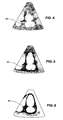
- Fig. 4 shows a conventional B-mode echocardiogram where the myocardium image 40 is surrounded by other tissue and superimposed clutter and noise 41.
- Fig. 5 shows a B-mode echocardiogram with the moving myocardium 40 enhanced by this invention.
- Fig. 6 shows a B-mode echocardiogram where the stationary tissue and clutter has been removed by the gate function 24 of this invention to display only the myocardium image 40.
- the clinician's scanning technique with this invention is similar to conventional B-mode image acquisition.
- the tissue motion detection mode can begin by pressing the appropriate key on the front panel. Moving tissue structures then will be superimposed on the video display, along with the conventional B-mode image.
- the user can select a number of different operating conditions. For example, the user can choose to image either the velocities, standard deviations, energies or accelerations of the moving tissue by switch means 22.
- the user can select either conventional color maps 10 to encode the direction as well as the magnitudes of the velocities or accelerations, or use the symmetric, non-directional color maps 20.
- the user can select a gray-scale "color" map 31 for the motion information and combine this with the B-mode information.
- the user can color the B-mode image and combine it with either a gray or color coded motion image.
- the clinician can also remove the underlying B-mode information (by reducing the B-mode gain), and image only the color Doppler information.
- the user can select a "gated" B-mode operation by switch means 23 where only the B-mode information from moving tissue is imaged as in Fig. 6.
- the B-mode image is displayed only if a Doppler signal is detected at the corresponding location in the image.
- the B-mode could be gated by the absence of a Doppler signal, thereby enhancing the boundary between the myocardium and the surrounding tissue.
- Stationary targets can be removed through the use of color maps, where the lowest velocities are assigned no color. Further, the range of velocities can be changed in the same way as with conventional color Doppler imaging by adjusting the sampling rate of the Doppler information.
- acceleration detection looks for differences in the velocities from one time frame to the next. In the case where same velocities are detected in the two adjacent time frames, there will be no acceleration measured. For moving tissue imaging, this loss of signal is distracting and counterintuitive. Therefore, for these operating cases, the acceleration processor will assign a low value of acceleration, instead of zero acceleration. The resulting image, while not truly displaying acceleration, has more diagnostic information. In the case where the velocities are zero in adjacent time frames, the acceleration is also assigned to zero.
- Tissue motion can be displayed in conjunction with a conventional M-mode display in similar ways as described for two-dimensional imaging.
Landscapes
- Engineering & Computer Science (AREA)
- Physics & Mathematics (AREA)
- Health & Medical Sciences (AREA)
- Life Sciences & Earth Sciences (AREA)
- Radar, Positioning & Navigation (AREA)
- Remote Sensing (AREA)
- General Physics & Mathematics (AREA)
- Computer Networks & Wireless Communication (AREA)
- Pathology (AREA)
- General Health & Medical Sciences (AREA)
- Acoustics & Sound (AREA)
- Biomedical Technology (AREA)
- Heart & Thoracic Surgery (AREA)
- Veterinary Medicine (AREA)
- Public Health (AREA)
- Animal Behavior & Ethology (AREA)
- Biophysics (AREA)
- Nuclear Medicine, Radiotherapy & Molecular Imaging (AREA)
- Radiology & Medical Imaging (AREA)
- Surgery (AREA)
- Molecular Biology (AREA)
- Medical Informatics (AREA)
- Biochemistry (AREA)
- Chemical & Material Sciences (AREA)
- Hematology (AREA)
- Analytical Chemistry (AREA)
- Immunology (AREA)
- Ultra Sonic Daignosis Equipment (AREA)
- Measurement Of Velocity Or Position Using Acoustic Or Ultrasonic Waves (AREA)
- Investigating Or Analyzing Materials By The Use Of Ultrasonic Waves (AREA)
Claims (21)
- Un dispositif d'imagerie ultrasonique comprenant un transducteur acoustique (2), un récepteur/ générateur de faisceau (4) couplé au transducteur (2), un détecteur Doppler (5) couplé au récepteur/ générateur de faisceau (4), un analyseur de signal Doppler (8) couplé au détecteur Doppler (5), et un dispositif d'affichage (9, 14) couplé à l'analyseur de signal Doppler (8), le dispositif d'affichage fonctionnant pour afficher des informations Doppler couleurs sous forme d'une image codée bidimensionnelle couleur de tissus en mouvement, le dispositif d'imagerie ultrasonique étant caractérisé en ce que :
l'analyseur de signal Doppler (8) est couplé au détecteur Doppler (5) sans aucun filtrage notable entre le détecteur Doppler (5) et l'analyseur de signal Doppler (8), l'analyseur de signal Doppler (8) traitant les informations Doppler couleurs à partir des tissus en mouvement à grande amplitude et basses fréquences en de multiples volumes le long d'une pluralité de lignes de balayage. - Dispositif selon la revendication 1, dans lequel le dispositif d'affichage (9, 14) comprend une fonction de cartographie couleur (30) qui n'attribue aucune couleur aux volumes caractérisés par une vitesse la plus basse.
- Dispositif selon la revendication 1 comprenant de plus un détecteur B-mode (12) couplé au transducteur (2) pour former une image B-mode desdits tissus en mouvement, ladite image B-mode représentant sensiblement l'intensité des échos reçus en provenance desdits tissus le long de plusieurs lignes de balayage B-mode, dans lequel l'invention est de plus caractérisée en ce que :
le dispositif d'affichage (9, 14) fonctionne pour afficher l'image B-mode sous forme d'une image bidimensionnelle avec des intensités d'échos codées en utilisant une première fonction de cartographie et pour augmenter l'image B-mode en affichant simultanément lesdites informations Doppler couleurs sous forme d'une image Doppler bidimensionnelle par l'utilisation d'une deuxième fonction, distincte, de cartographie, ladite image Doppler étant en coordination spatiale avec et superposée sur ladite image B-mode. - Dispositif selon la revendication 3 dans lequel les informations Doppler couleurs représentent des estimations de vitesses.
- Dispositif selon la revendication 3 dans lequel les informations Doppler couleurs représentent des estimations d'accélérations.
- Dispositif selon la revendication 3 dans lequel la couleur de la seconde fonction de cartographie représente des estimations d'accélération dérivées d'estimations de vitesse qui sont non-nulles mais identiques à une valeur non-nulle faible.
- Dispositif selon la revendication 3 dans lequel l'invention est de plus caractérisée en ce que le dispositif d'affichage comprend une porte (24) fonctionnant afin de déclencher l'image B-mode pour affichage seulement en présence d'informations Doppler acquises et traitées.
- Dispositif selon la revendication 1 dans lequel les informations Doppler représentent des estimations de vitesse, d'écart-type, d'énergie ou d'accélération.
- Dispositif selon la revendication 3 dans lequel la seconde fonction de cartographie représente la grandeur du mouvement avant et arrière sans distinction de direction du mouvement.
- Dispositif selon la revendication 3 dans lequel l'échelle de gris de la seconde fonction de cartographie représente les informations Doppler.
- Procédé pour former une image Doppler couleur en transmettant des ondes de pression acoustique, en recevant des échos en retour sur des lignes acoustiques balayées par un transducteur (2), en acquérant et en traitant des informations Doppler couleurs avec un détecteur Doppler (5) et un analyseur de signal Doppler (8), et en affichant lesdites informations Doppler couleurs sous forme d'une image codée bidimensionnelle couleur, les étapes d'affichage comportant l'affichage d'une image de codes couleur bidimensionnelle de tissus en mouvement, caractérisé en ce que :
l'étape d'acquisition et de traitement n'utilise aucun filtrage notable entre le détecteur Doppler (5) et l'analyseur de signal Doppler (8) de telle façon que les informations Doppler couleurs sont acquises à grande amplitude et basses fréquences à partir de tissus en mouvement en de multiples volumes le long d'une pluralité de lignes de balayage. - Procédé selon la revendication 11 dans laquelle l'étape d'affichage affiche lesdites informations Doppler couleurs en n'attribuant aucune couleur aux informations Doppler couleurs associées à une vitesse la plus basse.
- Procédé selon la revendication 11 de plus comprenant l'étape de moduler une valeur d'échantillonnage des informations Doppler couleurs dans l'étape d'acquisition et de traitement.
- Procédé selon la revendication Il de plus comprenant l'étape de dériver une image B-mode à partir d'échos reçus le long d'un ensemble de lignes de balayage qui sont les mêmes ou sont indépendantes des lignes acoustiques, caractérisée en ce que l'étape d'affichage affiche l'image B-mode en coordination spatiale avec et en superposition sur l'image codée couleur bidimensionnelle.
- Procédé selon la revendication 11 dans laquelle les informations Doppler représentent des estimations de vitesse.
- Procédé selon la revendication 11 dans laquelle les informations Doppler représentent des estimations d'accélération.
- Procédé selon la revendication 14 caractérisée par l'étape supplémentaire de déclenchement de l'image B-mode avec les informations Doppler couleurs.
- Procédé selon la revendication 11 dans laquelle les informations Doppler comportent des informations sur l'énergie Doppler.
- Procédé selon la revendication 11 dans laquelle les informations Doppler comportent des informations sur l'accélération Doppler.
- Procédé selon la revendication 1 dans laquelle les informations Doppler comportent des informations sur l'énergie Doppler.
- Procédé selon la revendication 1 dans laquelle les informations Doppler comportent des informations sur l'accélération Doppler.
Applications Claiming Priority (2)
| Application Number | Priority Date | Filing Date | Title |
|---|---|---|---|
| US07/962,145 US5285788A (en) | 1992-10-16 | 1992-10-16 | Ultrasonic tissue imaging method and apparatus with doppler velocity and acceleration processing |
| US962145 | 1992-10-16 |
Publications (3)
| Publication Number | Publication Date |
|---|---|
| EP0592967A2 EP0592967A2 (fr) | 1994-04-20 |
| EP0592967A3 EP0592967A3 (fr) | 1994-11-02 |
| EP0592967B1 true EP0592967B1 (fr) | 1998-11-25 |
Family
ID=25505481
Family Applications (1)
| Application Number | Title | Priority Date | Filing Date |
|---|---|---|---|
| EP93116372A Expired - Lifetime EP0592967B1 (fr) | 1992-10-16 | 1993-10-08 | Système et procédé d'imagerie ultrasonore de tissus, avec traitement Doppler en vitesse et accélération |
Country Status (7)
| Country | Link |
|---|---|
| US (2) | US5285788A (fr) |
| EP (1) | EP0592967B1 (fr) |
| JP (1) | JPH06233767A (fr) |
| AT (1) | ATE173835T1 (fr) |
| AU (1) | AU673851B2 (fr) |
| CA (1) | CA2108098C (fr) |
| DE (1) | DE69322230T2 (fr) |
Families Citing this family (111)
| Publication number | Priority date | Publication date | Assignee | Title |
|---|---|---|---|---|
| US5713363A (en) * | 1991-11-08 | 1998-02-03 | Mayo Foundation For Medical Education And Research | Ultrasound catheter and method for imaging and hemodynamic monitoring |
| US5325860A (en) * | 1991-11-08 | 1994-07-05 | Mayo Foundation For Medical Education And Research | Ultrasonic and interventional catheter and method |
| US5704361A (en) * | 1991-11-08 | 1998-01-06 | Mayo Foundation For Medical Education And Research | Volumetric image ultrasound transducer underfluid catheter system |
| US5482044A (en) * | 1992-01-14 | 1996-01-09 | Diasonics Ultrasound, Inc. | Direct demodulation in ultrasound instruments |
| US5622174A (en) * | 1992-10-02 | 1997-04-22 | Kabushiki Kaisha Toshiba | Ultrasonic diagnosis apparatus and image displaying system |
| US5738096A (en) * | 1993-07-20 | 1998-04-14 | Biosense, Inc. | Cardiac electromechanics |
| US6983179B2 (en) | 1993-07-20 | 2006-01-03 | Biosense, Inc. | Method for mapping a heart using catheters having ultrasonic position sensors |
| US6285898B1 (en) | 1993-07-20 | 2001-09-04 | Biosense, Inc. | Cardiac electromechanics |
| US5419328A (en) * | 1993-08-09 | 1995-05-30 | Hewlett-Packard Company | Mean squared speed and myocardial performance |
| US5415171A (en) * | 1993-08-09 | 1995-05-16 | Hewlett-Packard Company | Phase imaging and myocardial performance |
| US5433204A (en) * | 1993-11-16 | 1995-07-18 | Camilla Olson | Method of assessing placentation |
| DE4430720A1 (de) * | 1993-12-21 | 1995-06-22 | Zeiss Carl Fa | Vorrichtung und Verfahren zur Laser-Cyclophotokoagulation |
| US5363850A (en) * | 1994-01-26 | 1994-11-15 | Cardiovascular Imaging Systems, Inc. | Method for recognition and reduction of blood speckle in blood vessel imaging system |
| JP3833282B2 (ja) * | 1994-06-24 | 2006-10-11 | 株式会社東芝 | 超音波診断装置 |
| DE19524880C2 (de) * | 1994-07-15 | 2000-09-21 | Agilent Technologies Inc | Endokardiale Echtzeit-Ultraschallverschiebungsanzeige |
| US5615680A (en) * | 1994-07-22 | 1997-04-01 | Kabushiki Kaisha Toshiba | Method of imaging in ultrasound diagnosis and diagnostic ultrasound system |
| NO943214D0 (no) | 1994-08-30 | 1994-08-30 | Vingmed Sound As | Fremgangsmåte ved ultralydavbildning |
| US5471990A (en) * | 1994-11-23 | 1995-12-05 | Advanced Technology Laboratories, Inc. | Ultrasonic doppler power measurement and display system |
| JP3759184B2 (ja) * | 1994-12-21 | 2006-03-22 | ジーイー横河メディカルシステム株式会社 | 超音波血流表示方法および装置 |
| US5487389A (en) * | 1994-12-29 | 1996-01-30 | Siemens Medical Systems, Inc. | Ultrasonic Doppler imager having an adaptive tissue rejection filter with enhanced tissue motion sensitivity |
| JPH10511588A (ja) * | 1994-12-30 | 1998-11-10 | アキュソン コーポレイション | 体液の流れ又は組織の運動の画像を増強するための適応式時間フィルタリング |
| US6177923B1 (en) | 1994-12-30 | 2001-01-23 | Acuson Corporation | Imaging modality showing energy and velocity |
| WO1996021215A1 (fr) * | 1994-12-30 | 1996-07-11 | Acuson Corporation | Modalite d'imagerie indiquant l'energie et la vitesse |
| JP3406106B2 (ja) * | 1995-02-06 | 2003-05-12 | ジーイー横河メディカルシステム株式会社 | 超音波画像表示方法および超音波診断装置 |
| US5609155A (en) * | 1995-04-26 | 1997-03-11 | Acuson Corporation | Energy weighted parameter spatial/temporal filter |
| JPH08299342A (ja) * | 1995-05-15 | 1996-11-19 | Toshiba Corp | 超音波診断装置 |
| US5538003A (en) * | 1995-05-18 | 1996-07-23 | Hewlett-Packard Company | Quick method and apparatus for identifying a region of interest in an ultrasound display |
| US5615677A (en) * | 1995-08-04 | 1997-04-01 | The Board Of Trustees Of The Leland Stanford Junior University | MRI tracking of cyclical motion by fourier integration of velocity |
| JP3707882B2 (ja) * | 1995-11-21 | 2005-10-19 | 株式会社東芝 | 超音波診断装置 |
| US6915149B2 (en) | 1996-01-08 | 2005-07-05 | Biosense, Inc. | Method of pacing a heart using implantable device |
| AU1983397A (en) * | 1996-02-29 | 1997-09-16 | Acuson Corporation | Multiple ultrasound image registration system, method and transducer |
| US5669385A (en) * | 1996-03-13 | 1997-09-23 | Advanced Technology Laboratories, Inc. | Ultrasonic scanning of tissue motion in three dimensions |
| WO1997034530A1 (fr) * | 1996-03-18 | 1997-09-25 | Furuno Electric Company, Limited | Appareil de diagnostic a ultrasons |
| US5718229A (en) * | 1996-05-30 | 1998-02-17 | Advanced Technology Laboratories, Inc. | Medical ultrasonic power motion imaging |
| US5699805A (en) * | 1996-06-20 | 1997-12-23 | Mayo Foundation For Medical Education And Research | Longitudinal multiplane ultrasound transducer underfluid catheter system |
| US5749364A (en) * | 1996-06-21 | 1998-05-12 | Acuson Corporation | Method and apparatus for mapping pressure and tissue properties |
| NO963175D0 (no) * | 1996-07-30 | 1996-07-30 | Vingmed Sound As | Analyse- og målemetode |
| US5846202A (en) * | 1996-07-30 | 1998-12-08 | Acuson Corporation | Ultrasound method and system for imaging |
| US5709210A (en) * | 1996-07-30 | 1998-01-20 | Acuson Corporation | Ultrasound system for imaging |
| JP3657709B2 (ja) * | 1996-09-30 | 2005-06-08 | フクダ電子株式会社 | 超音波診断装置 |
| US6066097A (en) | 1997-10-22 | 2000-05-23 | Florida Atlantic University | Two dimensional ultrasonic scanning system and method |
| US5871447A (en) * | 1996-11-07 | 1999-02-16 | Acuson Corporation | Doppler energy-related parameters in an ultrasound imaging system |
| US6086539A (en) * | 1996-12-04 | 2000-07-11 | Acuson Corporation | Methods and apparatus for ultrasound image quantification |
| US5855557A (en) * | 1996-12-30 | 1999-01-05 | Siemens Medical Systems, Inc. | Ultrasonic imaging system and method for generating and displaying velocity field information |
| US7108663B2 (en) * | 1997-02-06 | 2006-09-19 | Exogen, Inc. | Method and apparatus for cartilage growth stimulation |
| US7789841B2 (en) * | 1997-02-06 | 2010-09-07 | Exogen, Inc. | Method and apparatus for connective tissue treatment |
| US5904659A (en) | 1997-02-14 | 1999-05-18 | Exogen, Inc. | Ultrasonic treatment for wounds |
| US6045508A (en) * | 1997-02-27 | 2000-04-04 | Acuson Corporation | Ultrasonic probe, system and method for two-dimensional imaging or three-dimensional reconstruction |
| US5882306A (en) * | 1997-04-11 | 1999-03-16 | Acuson Corporation | Ultrasound imaging methods and systems |
| US5997477A (en) * | 1997-04-14 | 1999-12-07 | The Trustees Of The University Of Pennsylvania | Apparatus for imaging an element within a tissue and method therefor |
| US5916168A (en) * | 1997-05-29 | 1999-06-29 | Advanced Technology Laboratories, Inc. | Three dimensional M-mode ultrasonic diagnostic imaging system |
| US6171247B1 (en) | 1997-06-13 | 2001-01-09 | Mayo Foundation For Medical Education And Research | Underfluid catheter system and method having a rotatable multiplane transducer |
| US6050944A (en) * | 1997-06-17 | 2000-04-18 | Acuson Corporation | Method and apparatus for frequency control of an ultrasound system |
| US6312379B1 (en) * | 1997-08-15 | 2001-11-06 | Acuson Corporation | Ultrasonic harmonic imaging system and method using waveform pre-distortion |
| US5873830A (en) * | 1997-08-22 | 1999-02-23 | Acuson Corporation | Ultrasound imaging system and method for improving resolution and operation |
| US5891037A (en) * | 1997-12-18 | 1999-04-06 | Acuson Corporation | Ultrasonic Doppler imaging system with frequency dependent focus |
| US5882315A (en) * | 1997-12-23 | 1999-03-16 | Acuson Corporation | Ultrasonic imaging method and image for doppler tissue parameters |
| ES2274626T3 (es) * | 1998-05-06 | 2007-05-16 | Exogen, Inc. | Vendajes con ultrasonido. |
| US6036643A (en) * | 1998-05-14 | 2000-03-14 | Advanced Technology Laboratories, Inc. | Ultrasonic harmonic doppler imaging |
| US6511426B1 (en) | 1998-06-02 | 2003-01-28 | Acuson Corporation | Medical diagnostic ultrasound system and method for versatile processing |
| EP1105044A1 (fr) | 1998-07-21 | 2001-06-13 | Acoustic Sciences Associates | Imagerie structurale synthetique et estimation de volume d'organes tissulaires biologiques |
| US6059731A (en) * | 1998-08-19 | 2000-05-09 | Mayo Foundation For Medical Education And Research | Simultaneous side-and-end viewing underfluid catheter |
| US6015384A (en) * | 1998-08-31 | 2000-01-18 | Acuson Corporation | Ultrasonic system and method for tissue viability imaging |
| US6174286B1 (en) | 1998-11-25 | 2001-01-16 | Acuson Corporation | Medical diagnostic ultrasound method and system for element switching |
| US6645147B1 (en) | 1998-11-25 | 2003-11-11 | Acuson Corporation | Diagnostic medical ultrasound image and system for contrast agent imaging |
| US6224556B1 (en) | 1998-11-25 | 2001-05-01 | Acuson Corporation | Diagnostic medical ultrasound system and method for using a sparse array |
| US6176828B1 (en) * | 1998-12-24 | 2001-01-23 | General Electric Company | Method and apparatus for optimal data mapping of power doppler images |
| US6017309A (en) * | 1998-12-31 | 2000-01-25 | Washburn; Michael J. | Ultrasound color flow display optimization by adjusting color maps |
| US6071241A (en) * | 1998-12-31 | 2000-06-06 | General Electric Company | Ultrasound color flow display optimization by adjustment of threshold using sampling |
| US6398736B1 (en) | 1999-03-31 | 2002-06-04 | Mayo Foundation For Medical Education And Research | Parametric imaging ultrasound catheter |
| US7410469B1 (en) | 1999-05-21 | 2008-08-12 | Exogen, Inc. | Apparatus and method for ultrasonically and electromagnetically treating tissue |
| AU768759B2 (en) | 1999-06-14 | 2004-01-08 | Exogen, Inc. | Method and kit for cavitation-induced tissue healing with low intensity ultrasound |
| US6234968B1 (en) | 1999-06-15 | 2001-05-22 | Acuson Corporation | 3-D diagnostic medical ultrasound imaging using a 1-D array |
| US6443894B1 (en) * | 1999-09-29 | 2002-09-03 | Acuson Corporation | Medical diagnostic ultrasound system and method for mapping surface data for three dimensional imaging |
| US6458082B1 (en) | 1999-09-29 | 2002-10-01 | Acuson Corporation | System and method for the display of ultrasound data |
| JP4377495B2 (ja) * | 1999-10-29 | 2009-12-02 | 株式会社東芝 | 超音波診断装置 |
| AU2002232679B2 (en) * | 2000-10-25 | 2005-12-22 | Exogen, Inc. | Transducer mounting assembly |
| GB0031664D0 (en) * | 2000-12-22 | 2001-02-07 | Univ London | Assessment of mycocardial contractility by measuring IVA (Isovolumic acceleration) |
| WO2002095653A2 (fr) * | 2001-05-18 | 2002-11-28 | Mayo Foundation For Medical Education And Research | Systeme et procede de gestion de donnees pour laboratoire d'echographie, |
| ITSV20010025A1 (it) * | 2001-06-29 | 2002-12-29 | Esaote Spa | Metodo e dispositivo per il rilevamento d'immagini di un ago di biopsia o simili ultrasuoni e durante un esame ecografico |
| US7429248B1 (en) | 2001-08-09 | 2008-09-30 | Exogen, Inc. | Method and apparatus for controlling acoustic modes in tissue healing applications |
| US6780155B2 (en) * | 2001-12-18 | 2004-08-24 | Koninklijke Philips Electronics | Method and system for ultrasound blood flow imaging and volume flow calculations |
| US6679843B2 (en) | 2002-06-25 | 2004-01-20 | Siemens Medical Solutions Usa , Inc. | Adaptive ultrasound image fusion |
| KR20060028682A (ko) * | 2003-06-02 | 2006-03-31 | 딥브리즈 엘티디. | 심혈관 음향을 분석하기 위한 방법과 시스템 |
| JP4473543B2 (ja) * | 2003-09-05 | 2010-06-02 | 株式会社東芝 | 超音波診断装置 |
| US20050075566A1 (en) * | 2003-09-19 | 2005-04-07 | Fuji Photo Film Co., Ltd. | Ultrasonice diagnosing apparatus |
| US6979295B2 (en) * | 2003-11-19 | 2005-12-27 | Ge Medical Systems Global Technology Company, Llc | Automatic color gain adjustments |
| EP1769265A1 (fr) * | 2004-07-13 | 2007-04-04 | Koninklijke Philips Electronics N.V. | Visualisation d'une image numerique standardisee avec controle de la lumiere ambiante |
| US20060036147A1 (en) * | 2004-07-20 | 2006-02-16 | Scimed Life Systems, Inc. | Systems and methods for detecting and presenting textural information from medical images |
| US7578790B2 (en) * | 2004-07-20 | 2009-08-25 | Boston Scientific Scimed, Inc. | Systems and methods for detecting and presenting textural information from medical images |
| US20060173318A1 (en) * | 2004-07-20 | 2006-08-03 | Scimed Life Systems Inc. | Systems and methods for detecting and presenting textural information from medical images |
| US7004906B1 (en) * | 2004-07-26 | 2006-02-28 | Siemens Medical Solutions Usa, Inc. | Contrast agent imaging with agent specific ultrasound detection |
| AU2005205820B2 (en) * | 2004-09-04 | 2011-04-14 | Smith & Nephew Plc | Ultrasound device and method of use |
| US9814439B2 (en) * | 2005-01-19 | 2017-11-14 | Siemens Medical Solutions Usa, Inc. | Tissue motion comparison display |
| US9144413B2 (en) * | 2005-03-30 | 2015-09-29 | Hitachi Medical Corporation | Ultrasonic diagnostic apparatus |
| US8211024B2 (en) * | 2005-06-06 | 2012-07-03 | Siemens Medical Solutions Usa, Inc. | Medical ultrasound pressure gradient measurement |
| CN100418482C (zh) * | 2005-08-11 | 2008-09-17 | 福州大学 | 彩超中组织多普勒图的加速度场检测方法及其装置 |
| WO2007049228A1 (fr) * | 2005-10-27 | 2007-05-03 | Koninklijke Philips Electronics, N.V. | Utilisation de l'acceleration tissulaire pour generer de meilleures formes d'ondes dti (imagerie doppler tissulaire) pour la crt (therapie de resynchronisation cardiaque) |
| US7374318B2 (en) * | 2005-11-07 | 2008-05-20 | Nancy Brooks | Lighted tubing |
| US20070167793A1 (en) * | 2005-12-14 | 2007-07-19 | Ep Medsystems, Inc. | Method and system for enhancing spectral doppler presentation |
| WO2007114305A1 (fr) * | 2006-03-31 | 2007-10-11 | National University Corporation Kyoto Institute Of Technology | Dispositif de traitement d'image, dispositif d'imagerie ultrasonore utilisant celui-ci, et procede de traitement d'image |
| WO2007136554A1 (fr) * | 2006-05-15 | 2007-11-29 | Mayo Foundation For Medical Education And Research | procÉdÉ pour imager des schÉmas de circulation sanguine intracavitaire |
| US20080015440A1 (en) * | 2006-07-13 | 2008-01-17 | The Regents Of The University Of Colorado | Echo particle image velocity (EPIV) and echo particle tracking velocimetry (EPTV) system and method |
| CN101600392A (zh) * | 2007-01-24 | 2009-12-09 | 皇家飞利浦电子股份有限公司 | 使用可调流体透镜对运动进行超声检测的方法和装置 |
| US20090156947A1 (en) * | 2007-05-22 | 2009-06-18 | Seward James B | Knowledgebased image informatics system and method |
| KR101117879B1 (ko) * | 2010-05-27 | 2012-03-07 | 삼성메디슨 주식회사 | 컬러 재구성 영상을 제공하는 초음파 시스템 및 방법 |
| JP5997177B2 (ja) * | 2010-12-23 | 2016-09-28 | コーニンクレッカ フィリップス エヌ ヴェKoninklijke Philips N.V. | 超音波撮像によるスリット開口部からの僧帽弁逆流の解析 |
| US10758209B2 (en) | 2012-03-09 | 2020-09-01 | The Johns Hopkins University | Photoacoustic tracking and registration in interventional ultrasound |
| BR112014031979A8 (pt) * | 2012-06-27 | 2021-02-23 | Koninklijke Philips Nv | sistema de ultrassom para diagnóstico que produz imagens do fluxo em cores da velocidade do fluxo ou movimento |
| US10806346B2 (en) | 2015-02-09 | 2020-10-20 | The Johns Hopkins University | Photoacoustic tracking and registration in interventional ultrasound |
| US11073612B2 (en) | 2015-07-23 | 2021-07-27 | Bk Medical, Aps | Flow acceleration estimation directly from beamformed ultrasound data |
Family Cites Families (12)
| Publication number | Priority date | Publication date | Assignee | Title |
|---|---|---|---|---|
| FR2574280B1 (fr) * | 1984-12-07 | 1988-11-25 | Inst Nat Sante Rech Med | Procede et dispositif de determination de caracteristiques cardiovasculaires par voie externe et leur application aux cardiopathies |
| JPS61191347A (ja) * | 1985-02-19 | 1986-08-26 | 株式会社日立メデイコ | 超音波診断装置 |
| US4789831A (en) * | 1985-08-20 | 1988-12-06 | North American Philips Corporation | Producing pseudocolor magnetic resonance images |
| US4690150A (en) * | 1985-08-20 | 1987-09-01 | North American Philips Corporation | Producing pseudocolor images for diagnostic ultrasound imaging |
| JPH01310648A (ja) * | 1988-06-08 | 1989-12-14 | Toshiba Corp | 超音波血流イメージング装置 |
| US5014710A (en) * | 1988-09-13 | 1991-05-14 | Acuson Corporation | Steered linear color doppler imaging |
| US5165413A (en) * | 1988-09-13 | 1992-11-24 | Acuson Corporation | Steered linear color doppler imaging |
| JPH0767449B2 (ja) * | 1989-01-24 | 1995-07-26 | アロカ株式会社 | 超音波ドプラ診断装置 |
| US5190044A (en) * | 1990-03-30 | 1993-03-02 | Kabushiki Kaisha Toshiba | Ultrasonic blood flow imaging apparatus |
| US5197477A (en) * | 1990-10-12 | 1993-03-30 | Advanced Technology Laboratories, Inc. | Ultrasonic doppler flow measurement system with tissue motion discrimination |
| US5099848A (en) * | 1990-11-02 | 1992-03-31 | University Of Rochester | Method and apparatus for breast imaging and tumor detection using modal vibration analysis |
| US5409010A (en) * | 1992-05-19 | 1995-04-25 | Board Of Regents Of The University Of Washington | Vector doppler medical devices for blood velocity studies |
-
1992
- 1992-10-16 US US07/962,145 patent/US5285788A/en not_active Ceased
-
1993
- 1993-10-08 DE DE69322230T patent/DE69322230T2/de not_active Expired - Lifetime
- 1993-10-08 CA CA002108098A patent/CA2108098C/fr not_active Expired - Fee Related
- 1993-10-08 AT AT93116372T patent/ATE173835T1/de not_active IP Right Cessation
- 1993-10-08 EP EP93116372A patent/EP0592967B1/fr not_active Expired - Lifetime
- 1993-10-11 AU AU48951/93A patent/AU673851B2/en not_active Ceased
- 1993-10-15 JP JP5258311A patent/JPH06233767A/ja active Pending
-
1996
- 1996-02-14 US US08/601,262 patent/USRE35720E/en not_active Expired - Lifetime
Non-Patent Citations (1)
| Title |
|---|
| JP-H2-193650 * |
Also Published As
| Publication number | Publication date |
|---|---|
| USRE35720E (en) | 1998-02-03 |
| US5285788A (en) | 1994-02-15 |
| ATE173835T1 (de) | 1998-12-15 |
| CA2108098A1 (fr) | 1994-04-17 |
| DE69322230D1 (de) | 1999-01-07 |
| EP0592967A2 (fr) | 1994-04-20 |
| JPH06233767A (ja) | 1994-08-23 |
| DE69322230T2 (de) | 1999-06-17 |
| EP0592967A3 (fr) | 1994-11-02 |
| AU673851B2 (en) | 1996-11-28 |
| AU4895193A (en) | 1994-05-05 |
| CA2108098C (fr) | 2001-06-05 |
Similar Documents
| Publication | Publication Date | Title |
|---|---|---|
| EP0592967B1 (fr) | Système et procédé d'imagerie ultrasonore de tissus, avec traitement Doppler en vitesse et accélération | |
| US7713204B2 (en) | Image data processing method and apparatus for ultrasonic diagnostic apparatus, and image processing apparatus | |
| EP1697759B1 (fr) | Procédé et système d'imagerie diagnostique à ultrasons à régulation automatique de la résolution et de la fréquence de rafraichissement d'images | |
| US6390980B1 (en) | Spatial compounding with ultrasonic doppler signal information | |
| EP1358507B1 (fr) | Traitement d'images adaptatif pour composition spatiale | |
| USRE38209E1 (en) | Diagnostic ultrasound system | |
| US6406430B1 (en) | Ultrasound image display by combining enhanced flow imaging in B-mode and color flow mode | |
| EP1176910B1 (fr) | Procede et appareil de suivi automatique de vaisseau sanguin en imagerie ultrasonore | |
| US6620103B1 (en) | Ultrasonic diagnostic imaging system for low flow rate contrast agents | |
| US5882306A (en) | Ultrasound imaging methods and systems | |
| EP2392264B1 (fr) | Filtrage de signal d'écho parasite utilisant des vecteurs propres dans un système ultrasonore | |
| JP2772045B2 (ja) | 超音波診断装置 | |
| EP2486421B1 (fr) | Imagerie ultrasonore anéchoïque | |
| JP2002224114A (ja) | 超音波診断装置及び超音波診断方法 | |
| JP3688562B2 (ja) | 超音波診断装置 | |
| US20210321981A1 (en) | Systems and methods for performing bi-plane imaging | |
| US5081996A (en) | Ultrasonic imaging apparatus | |
| JP3472604B2 (ja) | 超音波ドプラ診断装置 | |
| JP2002034987A (ja) | Bモード画像生成方法および超音波診断装置 | |
| JP2005006718A (ja) | 超音波診断装置 | |
| JP3332090B2 (ja) | 超音波診断装置 | |
| JPH08206113A (ja) | 超音波イメージング処理方法及び超音波イメージング装置 | |
| JPH03133437A (ja) | 超音波診断装置 |
Legal Events
| Date | Code | Title | Description |
|---|---|---|---|
| PUAI | Public reference made under article 153(3) epc to a published international application that has entered the european phase |
Free format text: ORIGINAL CODE: 0009012 |
|
| AK | Designated contracting states |
Kind code of ref document: A2 Designated state(s): AT BE CH DE DK ES FR GB GR IE IT LI LU MC NL PT SE |
|
| PUAL | Search report despatched |
Free format text: ORIGINAL CODE: 0009013 |
|
| AK | Designated contracting states |
Kind code of ref document: A3 Designated state(s): AT BE CH DE DK ES FR GB GR IE IT LI LU MC NL PT SE |
|
| 17P | Request for examination filed |
Effective date: 19950502 |
|
| 17Q | First examination report despatched |
Effective date: 19961218 |
|
| GRAG | Despatch of communication of intention to grant |
Free format text: ORIGINAL CODE: EPIDOS AGRA |
|
| GRAG | Despatch of communication of intention to grant |
Free format text: ORIGINAL CODE: EPIDOS AGRA |
|
| GRAG | Despatch of communication of intention to grant |
Free format text: ORIGINAL CODE: EPIDOS AGRA |
|
| GRAH | Despatch of communication of intention to grant a patent |
Free format text: ORIGINAL CODE: EPIDOS IGRA |
|
| GRAH | Despatch of communication of intention to grant a patent |
Free format text: ORIGINAL CODE: EPIDOS IGRA |
|
| GRAA | (expected) grant |
Free format text: ORIGINAL CODE: 0009210 |
|
| AK | Designated contracting states |
Kind code of ref document: B1 Designated state(s): AT BE CH DE DK ES FR GB GR IE IT LI LU MC NL PT SE |
|
| PG25 | Lapsed in a contracting state [announced via postgrant information from national office to epo] |
Ref country code: SE Free format text: THE PATENT HAS BEEN ANNULLED BY A DECISION OF A NATIONAL AUTHORITY Effective date: 19981125 Ref country code: NL Free format text: LAPSE BECAUSE OF FAILURE TO SUBMIT A TRANSLATION OF THE DESCRIPTION OR TO PAY THE FEE WITHIN THE PRESCRIBED TIME-LIMIT Effective date: 19981125 Ref country code: LI Free format text: LAPSE BECAUSE OF FAILURE TO SUBMIT A TRANSLATION OF THE DESCRIPTION OR TO PAY THE FEE WITHIN THE PRESCRIBED TIME-LIMIT Effective date: 19981125 Ref country code: GR Free format text: LAPSE BECAUSE OF NON-PAYMENT OF DUE FEES Effective date: 19981125 Ref country code: ES Free format text: THE PATENT HAS BEEN ANNULLED BY A DECISION OF A NATIONAL AUTHORITY Effective date: 19981125 Ref country code: CH Free format text: LAPSE BECAUSE OF FAILURE TO SUBMIT A TRANSLATION OF THE DESCRIPTION OR TO PAY THE FEE WITHIN THE PRESCRIBED TIME-LIMIT Effective date: 19981125 Ref country code: AT Free format text: LAPSE BECAUSE OF FAILURE TO SUBMIT A TRANSLATION OF THE DESCRIPTION OR TO PAY THE FEE WITHIN THE PRESCRIBED TIME-LIMIT Effective date: 19981125 |
|
| REF | Corresponds to: |
Ref document number: 173835 Country of ref document: AT Date of ref document: 19981215 Kind code of ref document: T |
|
| REG | Reference to a national code |
Ref country code: CH Ref legal event code: EP |
|
| REF | Corresponds to: |
Ref document number: 69322230 Country of ref document: DE Date of ref document: 19990107 |
|
| REG | Reference to a national code |
Ref country code: IE Ref legal event code: FG4D |
|
| ET | Fr: translation filed | ||
| ITF | It: translation for a ep patent filed | ||
| PG25 | Lapsed in a contracting state [announced via postgrant information from national office to epo] |
Ref country code: PT Free format text: LAPSE BECAUSE OF FAILURE TO SUBMIT A TRANSLATION OF THE DESCRIPTION OR TO PAY THE FEE WITHIN THE PRESCRIBED TIME-LIMIT Effective date: 19990225 Ref country code: DK Free format text: LAPSE BECAUSE OF FAILURE TO SUBMIT A TRANSLATION OF THE DESCRIPTION OR TO PAY THE FEE WITHIN THE PRESCRIBED TIME-LIMIT Effective date: 19990225 |
|
| NLV1 | Nl: lapsed or annulled due to failure to fulfill the requirements of art. 29p and 29m of the patents act | ||
| REG | Reference to a national code |
Ref country code: CH Ref legal event code: PL |
|
| PLBE | No opposition filed within time limit |
Free format text: ORIGINAL CODE: 0009261 |
|
| STAA | Information on the status of an ep patent application or granted ep patent |
Free format text: STATUS: NO OPPOSITION FILED WITHIN TIME LIMIT |
|
| PG25 | Lapsed in a contracting state [announced via postgrant information from national office to epo] |
Ref country code: LU Free format text: LAPSE BECAUSE OF NON-PAYMENT OF DUE FEES Effective date: 19991008 Ref country code: IE Free format text: LAPSE BECAUSE OF NON-PAYMENT OF DUE FEES Effective date: 19991008 |
|
| 26N | No opposition filed | ||
| PG25 | Lapsed in a contracting state [announced via postgrant information from national office to epo] |
Ref country code: MC Free format text: LAPSE BECAUSE OF NON-PAYMENT OF DUE FEES Effective date: 20000430 |
|
| REG | Reference to a national code |
Ref country code: IE Ref legal event code: MM4A |
|
| PGFP | Annual fee paid to national office [announced via postgrant information from national office to epo] |
Ref country code: GB Payment date: 20000921 Year of fee payment: 8 |
|
| PGFP | Annual fee paid to national office [announced via postgrant information from national office to epo] |
Ref country code: BE Payment date: 20001017 Year of fee payment: 8 |
|
| PG25 | Lapsed in a contracting state [announced via postgrant information from national office to epo] |
Ref country code: GB Free format text: LAPSE BECAUSE OF NON-PAYMENT OF DUE FEES Effective date: 20011008 |
|
| PG25 | Lapsed in a contracting state [announced via postgrant information from national office to epo] |
Ref country code: BE Free format text: LAPSE BECAUSE OF NON-PAYMENT OF DUE FEES Effective date: 20011031 |
|
| REG | Reference to a national code |
Ref country code: GB Ref legal event code: IF02 |
|
| BERE | Be: lapsed |
Owner name: ACUSON CORP. Effective date: 20011031 |
|
| GBPC | Gb: european patent ceased through non-payment of renewal fee |
Effective date: 20011008 |
|
| REG | Reference to a national code |
Ref country code: FR Ref legal event code: TP |
|
| REG | Reference to a national code |
Ref country code: DE Ref legal event code: R081 Ref document number: 69322230 Country of ref document: DE Owner name: SIEMENS MEDICAL SOLUTIONS USA, INC. (N.D. GES., US Free format text: FORMER OWNER: ACUSON CORP., MOUNTAIN VIEW, US Effective date: 20120222 |
|
| PGFP | Annual fee paid to national office [announced via postgrant information from national office to epo] |
Ref country code: FR Payment date: 20121031 Year of fee payment: 20 |
|
| PGFP | Annual fee paid to national office [announced via postgrant information from national office to epo] |
Ref country code: IT Payment date: 20121030 Year of fee payment: 20 |
|
| PGFP | Annual fee paid to national office [announced via postgrant information from national office to epo] |
Ref country code: DE Payment date: 20121216 Year of fee payment: 20 |
|
| REG | Reference to a national code |
Ref country code: DE Ref legal event code: R071 Ref document number: 69322230 Country of ref document: DE |
|
| PG25 | Lapsed in a contracting state [announced via postgrant information from national office to epo] |
Ref country code: DE Free format text: LAPSE BECAUSE OF EXPIRATION OF PROTECTION Effective date: 20131009 |