EP0592987B1 - Vibratordrehmessaufnehmer - Google Patents
Vibratordrehmessaufnehmer Download PDFInfo
- Publication number
- EP0592987B1 EP0592987B1 EP93116443A EP93116443A EP0592987B1 EP 0592987 B1 EP0592987 B1 EP 0592987B1 EP 93116443 A EP93116443 A EP 93116443A EP 93116443 A EP93116443 A EP 93116443A EP 0592987 B1 EP0592987 B1 EP 0592987B1
- Authority
- EP
- European Patent Office
- Prior art keywords
- vibrating body
- vibrating
- case
- vibratory gyroscope
- inner size
- Prior art date
- Legal status (The legal status is an assumption and is not a legal conclusion. Google has not performed a legal analysis and makes no representation as to the accuracy of the status listed.)
- Expired - Lifetime
Links
- 230000035945 sensitivity Effects 0.000 description 15
- 230000000052 comparative effect Effects 0.000 description 4
- 230000004048 modification Effects 0.000 description 4
- 238000012986 modification Methods 0.000 description 4
- PXHVJJICTQNCMI-UHFFFAOYSA-N Nickel Chemical compound [Ni] PXHVJJICTQNCMI-UHFFFAOYSA-N 0.000 description 2
- 239000000919 ceramic Substances 0.000 description 2
- 230000007613 environmental effect Effects 0.000 description 2
- 239000000463 material Substances 0.000 description 2
- 238000000034 method Methods 0.000 description 2
- 229910000570 Cupronickel Inorganic materials 0.000 description 1
- 229910001030 Iron–nickel alloy Inorganic materials 0.000 description 1
- 229910000792 Monel Inorganic materials 0.000 description 1
- BQCADISMDOOEFD-UHFFFAOYSA-N Silver Chemical compound [Ag] BQCADISMDOOEFD-UHFFFAOYSA-N 0.000 description 1
- 229910045601 alloy Inorganic materials 0.000 description 1
- 239000000956 alloy Substances 0.000 description 1
- 229910052782 aluminium Inorganic materials 0.000 description 1
- XAGFODPZIPBFFR-UHFFFAOYSA-N aluminium Chemical compound [Al] XAGFODPZIPBFFR-UHFFFAOYSA-N 0.000 description 1
- YOCUPQPZWBBYIX-UHFFFAOYSA-N copper nickel Chemical compound [Ni].[Cu] YOCUPQPZWBBYIX-UHFFFAOYSA-N 0.000 description 1
- 239000013078 crystal Substances 0.000 description 1
- 230000000694 effects Effects 0.000 description 1
- 239000007772 electrode material Substances 0.000 description 1
- 239000011521 glass Substances 0.000 description 1
- PCHJSUWPFVWCPO-UHFFFAOYSA-N gold Chemical compound [Au] PCHJSUWPFVWCPO-UHFFFAOYSA-N 0.000 description 1
- 229910052737 gold Inorganic materials 0.000 description 1
- 239000010931 gold Substances 0.000 description 1
- 229910052751 metal Inorganic materials 0.000 description 1
- 239000002184 metal Substances 0.000 description 1
- 229910052759 nickel Inorganic materials 0.000 description 1
- 239000010453 quartz Substances 0.000 description 1
- VYPSYNLAJGMNEJ-UHFFFAOYSA-N silicon dioxide Inorganic materials O=[Si]=O VYPSYNLAJGMNEJ-UHFFFAOYSA-N 0.000 description 1
- 229910052709 silver Inorganic materials 0.000 description 1
- 239000004332 silver Substances 0.000 description 1
- 238000004544 sputter deposition Methods 0.000 description 1
- 229920003002 synthetic resin Polymers 0.000 description 1
- 239000000057 synthetic resin Substances 0.000 description 1
- 239000010409 thin film Substances 0.000 description 1
- 238000007738 vacuum evaporation Methods 0.000 description 1
- 238000003466 welding Methods 0.000 description 1
Images


Classifications
-
- G—PHYSICS
- G01—MEASURING; TESTING
- G01C—MEASURING DISTANCES, LEVELS OR BEARINGS; SURVEYING; NAVIGATION; GYROSCOPIC INSTRUMENTS; PHOTOGRAMMETRY OR VIDEOGRAMMETRY
- G01C19/00—Gyroscopes; Turn-sensitive devices using vibrating masses; Turn-sensitive devices without moving masses; Measuring angular rate using gyroscopic effects
- G01C19/56—Turn-sensitive devices using vibrating masses, e.g. vibratory angular rate sensors based on Coriolis forces
- G01C19/5642—Turn-sensitive devices using vibrating masses, e.g. vibratory angular rate sensors based on Coriolis forces using vibrating bars or beams
- G01C19/5663—Manufacturing; Trimming; Mounting; Housings
Definitions
- the present invention relates to a vibratory gyroscope, and particularly, to a vibratory gyroscope which is used, for example, in a system for protecting an unsteady hold mounted on a VTR camera or the like.
- Fig. 11 is a perspective view showing an example of a conventional vibratory gyroscope
- Fig. 12 is a sectional view taken along the line XII-XII of Fig. 11
- Fig. 13 is a sectional view taken along the line XIII-XIII of Fig. 11.
- the vibratory gyroscope 1 comprises a vibrator 2.
- the vibrator 2 comprises a regular triangular prism-shaped vibrating body 3.
- piezoelectric elements 4a, 4b and 4c are formed respectively.
- the vibrating body 3 is supported above a base plate 6 of 6.7 mm x 20.4 mm in a plan view by two supporting members 5a and 5b.
- a box type case 7 of 6.7 mm width, 20.4 mm length and 5 mm height in inner sizes is fixed to the base plate 6 so as to cover the vibrating body 3 and so on.
- the case 7 is to protect the vibrating body 3 and so on from an outside effect.
- the vibrating body 3 bends and vibrates vertically at about 25.5 kHz. In this case, the vibrating body 3 bends and vibrates forming its longitudinal center portion into an antinodal point, and two portions supported by the supporting members 5a and 5b into nodal points.
- the half-wavelength of a sound wave at a vibrating frequency of the vibrating body 3 is almost equal to the inner size 6.7 mm in the width of the case 7, depending upon an environmental temperature on some occasions. That is, at an environmental temperature of about 20 °C, the sound velocity is about 430 m/sec., thus the half-wavelength of the sound wave at a vibrating frequency of about 25.5 kHz becomes about 6.7 mm.
- the vibrating body 3 resonates with the case 7 to produce a standing wave, thereby its sensitivity rapidly changes. In this way, when the sensitivity of the vibratory gyroscope 1 rapidly changes, it becomes difficult to accurately detect the rotational angular velocity.
- a vibratory gyroscope comprises a cylinder-shaped vibrating body, and a case covered the vibrating body, wherein in a direction which is orthogonal to a vibrating direction of the vibrating body at no rotation and is orthogonal to the axis direction of the vibrating body, at least an inner size of portions of the case opposed to the vibrating body is different from an integer multiple of the half-wavelength of a sound wave at a vibrating frequency of the vibrating body.
- the inner size of the portions of the case opposed to the vibrating body is different from an integer multiple of the half-wavelength of a sound wave at the vibrating frequency of the vibrating body, thus the vibrating body does not resonate with the case at rotation of the vibratory gyroscope even when the temperature changes, and its sensitivity does not rapidly change.
- a vibratory gyroscope wherein its sensitivity does not rapidly change against temperature change can be obtained.
- the vibratory gyroscope in accordance with the present invention can correctly detect a rotational angular velocity against temperature change.
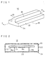
- Fig. 1 is a perspective view showing one embodiment of the present invention.
- Fig. 2 is a sectional view taken along the line II-II of Fig. 1.
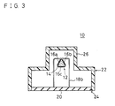
- Fig. 3 is a sectional view taken along the line III-III of Fig. 1.
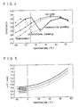
- Fig. 4 is a graph showing characteristics of sensitivity change against temperature change in the embodiment of Figs. 1-3, in the conventional example of Figs. 11-13, in a comparative example having a case of an inner size extended in the direction of the width in the conventional example, and in a vibratory gyroscope having no case.
- Fig. 5 is a graph showing relations between temperatures and half-wavelengths of sound waves on 25 kHz, 25.5 kHz and 26 kHz.
- Fig. 6 is a perspective view showing a modification of the embodiment of Fig. 1.
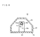
- Fig. 7 is a perspective view showing a modification of the embodiment of Fig. 6.
- Fig. 8 is a sectional view taken along the line VIII-VIII of Fig. 7.
- Fig. 9 is a perspective view showing another embodiment of the present invention.
- Fig. 10 is a perspective view showing still another embodiment of the present invention.
- Fig. 11 is a perspective view showing an example of a conventional vibratory gyroscope.
- Fig. 12 is a sectional view taken along the line XII-XII of Fig. 11.
- Fig. 13 is a sectional view taken along the line XIII-XIII of Fig. 11.
- Fig. 1 is a perspective view showing one embodiment of the present invention
- Fig. 2 is a sectional view taken along the line II-II of Fig. 1
- Fig. 3 is a sectional view taken along the line III-III of Fig. 1.
- the vibratory gyroscope 10 comprises a vibrator 12.
- the vibrator 12 comprises a regular triangular prism-shaped vibrating body 14.
- the vibrating body 14 is formed with a material which generally generates a mechanical vibration such as elinver, iron-nickel alloy, quartz, glass, crystal, ceramics and the like.
- piezoelectric elements 16a, 16b and 16c are formed, respectively.
- Each of the piezoelectric elements 16a-16c includes a piezoelectric layer consisting of, for example, ceramics, and on both surfaces of the piezoelectric layer, electrodes are formed respectively.
- the electrodes are formed with an electrode material such as gold, silver, aluminum, nickel, copper-nickel alloy (Monel Metal) and the like, and by means of thin-film forming techniques such as sputtering and vacuum evaporation or by means of printing techniques depending on the material.
- the vicinities of two nodal points of the vibrating body 14 are respectively supported by U-shaped supporting members 18a and 18b consisting of, for example, a metal wire. Center portions of the supporting members 18a and 18b are respectively secured to the vicinities of the two nodal points of the vibrating body 14, by welding or by bonding with a conductive paste. End portions of the supporting members 18a and 18b are secured to one surface of a base plate 20 of, for example, 6.7 mm x 20.4 mm in a plan view.
- upper two piezoelectric elements 16a and 16b are used for driving and detecting
- lower one piezoelectric element 16c is used for feedback.
- the vibrating body 14 bends and vibrates, and the same wave forms are outputted from the piezoelectric elements 16a and 16b. In this case, the vibrating body 14 bends and vibrates vertically at about 25.5 kHz.
- the vibrator 12 is covered with a case 22 consisting of, for example, synthetic resin.
- the case 22 has, in its bottom, an opening portion 24 of the same inner size as the base plate 20.
- An upper portion 26 of the case 22 is formed into a small size in the direction of the width.
- the upper portion 26 of the case 22 is so formed into a narrow size in the direction of the width that the inner size in the direction of the width is, for example, a length of 3 mm.
- the opening portion 24 is adhered to the base plate 20 so as to cover the vibrator 12 with the upper portion 26.
- the vibratory gyroscope 10 in a direction which is orthogonal to the vibrating direction of the vibrating body 14 at no rotation or to the vertical direction and is orthogonal to the axis direction of the vibrating body 14, an inner size of portions of the case 22 opposed to the vibrating body 14 is different from an integer multiple of the half-wavelength of a sound wave at a vibrating frequency of the vibrating body 14, thus the vibrating body 14 does not resonate with the case 22 at rotation of the vibratory gyroscope even when temperature changes, and its sensitivity does not rapidly change.
- the vibratory gyroscope 10 can correctly detect a rotational angular velocity against temperature change.
- Fig. 4 is a graph showing characteristics of sensitivity change against temperature change in the embodiment of Figs. 1-3, in the conventional example of Figs. 11-13, in a comparative example having a case of an inner size extended into 6.8 mm in the direction of the width in the conventional example, and in a vibratory gyroscope having no case.
- the half-wavelength on the vibrating frequency of the vibrating body is nearly equal to the inner size of the case in portions opposed to the vibrating body, as shown in Table 1 which shows the relations between temperatures T (°C), sound velocities V (m/sec), and half-wavelengths ⁇ /2 (mm) of sound waves on 25 kHz, 25.5 kHz, and 26 kHz, and as shown in Fig. 5 which shows the relations between temperatures (°C) and half-wavelengths ⁇ /2 (mm) of the sound waves on 25 kHz, 25.5 kHz and 26 kHz.
- the upper portion 26 of the case 22 is formed into a narrow width as compared with the conventional example of Figs. 11-13, thus the whole of the vibratory gyroscope can be miniaturized.
- Fig. 6 is a perspective view showing a modification of the embodiment of Fig. 1.
- the inside and outside faces of both longitudinal ends of the upper portion 26 of the case 22 are curved outward respectively, while, in the embodiment of Fig. 6, the inside and outside faces of both the longitudinal ends of the upper portion 26 of the case 22 are formed into inclined faces.
- the sensitivity does not rapidly change against temperature change similar to the embodiment of Fig. 1, thus a rotational angular velocity can be correctly measured. Furthermore, in the embodiment of Fig. 6, the whole of the vibratory gyroscope can be miniaturized as compared with the conventional example of in Figs. 11-13.
- Fig. 7 is a perspective view showing a modification of the embodiment of Fig. 6, and Fig. 8 is a sectional view taken along the line VIII-VIII of Fig. 7.
- the inside and outside faces of both the transversal ends of the upper portion 26 of the case 22 are especially formed into inclined faces as compared with the embodiment of Fig. 6.
- Fig. 9 is a perspective view showing another embodiment of the present invention.
- the width portion of the upper portion 26 of the case 22 extending from one longitudinal end to the other longitudinal end is formed into a narrow width, however in the embodiment of Fig. 9, the inside and outside widths of only a longitudinal center portion of the upper portion 26 of the case 22 opposed to the vibrating body 14 are formed into narrow widths.
- the inside and outside faces are formed into inclined faces respectively.
- the inside and outside faces of both the longitudinal ends of the upper portion 26 of the case 22 are curved outward respectively.
- the sensitivity does not rapidly change against temperature change, thus a rotational angular velocity can be correctly detected.
- Fig. 10 is a perspective view showing still another embodiment of the present invention.
- the width of the upper portion 26 of the case 22 is formed into a narrow one, however in the embodiment of Fig. 10, only a width between both elliptic center portions 28 which include portions opposed to the vibrating body 14 in the direction of the width is formed into a narrow width in the case 22.
- a regular prism-shaped vibrating body is used, however a circular cylinder-shaped vibrating body, a square prism-shaped vibrating body or another cylinder-shaped vibrating may be used in the present invention.
- piezoelectric elements are used, although only two piezoelectric elements for driving and detecting may be used, and a number of piezoelectric elements used may be optionally changed in the present invention.
- the inner size of the case 22 is made to be different from an integer multiple of the half-wavelength of a sound wave at the vibrating frequency of the vibrating body 14.
- the inner size of the case in the vibrating direction of the vibrating body 14 at no rotation or the inner size of the case in the axial direction of the vibrating body 14 may be made to be different from an integer multiple of the half-wavelength of a sound wave at a vibration frequency of the vibrating body 14.
- the inner size of the case 22 in the vibrating direction of the vibrating body 14 at no rotation is made to be different from an integer multiple of a half-wavelength of a sound wave on a vibrating frequency of the vibrating body 14, though the output at no rotation is almost zero, and the sensitivity at no rotation does not rapidly change against temperature change.
- the vibrating frequency of the vibrating body 14 is about 25.5 kHz, although the present invention can be applied to a vibratory gyroscope having a vibrating body vibrated at another frequency.
- the vibrator and so on is enclosed with only the case in each embodiment mentioned above, the vibrator, the base plate and so on may be enclosed with only a case.
Landscapes
- Engineering & Computer Science (AREA)
- Manufacturing & Machinery (AREA)
- Physics & Mathematics (AREA)
- General Physics & Mathematics (AREA)
- Radar, Positioning & Navigation (AREA)
- Remote Sensing (AREA)
- Gyroscopes (AREA)
Claims (4)
- Ein Vibrationsgyroskop mit folgenden Merkmalen:einem zylindrisch geformten Vibrationskörper; undeinem Gehäuse, das den Vibrationskörper häust,wobei in einer Richtung, die senkrecht zu einer Vibrationsrichtung des Vibrationskörpers bei fehlender Drehung ist, und die senkrecht zu der Achsenrichtung des Vibrationskörpers ist, die innere Abmessung zumindest von Abschnitten des Gehäuses, die dem Vibrationskörper gegenüberliegen, sich von einem ganzzahligen Vielfachen der Halbwellenlänge einer Schallwelle bei einer Vibrationsfrequenz des Vibrationskörpers unterscheidet.
- Ein Vibrationsgyroskop gemäß Anspruch 1,bei dem die Vibrationsfrequenz des Vibrationskörpers 25 bis 26 kHz beträgt, undbei dem die innere Größe des Gehäuses 3 mm beträgt.
- Ein Vibrationsgyroskop gemäß Anspruch 1,
bei dem sich die innere Abmessung von zumindest den Abschnitten des Gehäuses, die dem Vibrationskörper gegenüberliegen, in der Vibrationsrichtung des Vibrationskörpers bei fehlender Drehung von einem ganzzahligen Vielfachen der Halbwellenlänge der Schallwelle bei der Vibrationsfrequenz des Vibrationskörpers unterscheidet. - Ein Vibrationsgyroskop gemäß Anspruch 1,
bei dem sich die innere Abmessung von zumindest den Abschnitten des Gehäuses, die dem Vibrationskörper gegenüberliegen, in der axialen Richtung des Vibrationskörpers von einem ganzzahligen Vielfachen der Halbwellenlänge der Schallwelle bei der Vibrationsfrequenz des Vibrationskörpers unterscheidet.
Applications Claiming Priority (2)
| Application Number | Priority Date | Filing Date | Title |
|---|---|---|---|
| JP304842/92 | 1992-10-16 | ||
| JP30484292A JP3627247B2 (ja) | 1992-10-16 | 1992-10-16 | 振動ジャイロ |
Publications (2)
| Publication Number | Publication Date |
|---|---|
| EP0592987A1 EP0592987A1 (de) | 1994-04-20 |
| EP0592987B1 true EP0592987B1 (de) | 1997-12-03 |
Family
ID=17937925
Family Applications (1)
| Application Number | Title | Priority Date | Filing Date |
|---|---|---|---|
| EP93116443A Expired - Lifetime EP0592987B1 (de) | 1992-10-16 | 1993-10-11 | Vibratordrehmessaufnehmer |
Country Status (4)
| Country | Link |
|---|---|
| US (1) | US5479822A (de) |
| EP (1) | EP0592987B1 (de) |
| JP (1) | JP3627247B2 (de) |
| DE (1) | DE69315531T2 (de) |
Families Citing this family (1)
| Publication number | Priority date | Publication date | Assignee | Title |
|---|---|---|---|---|
| RU2123219C1 (ru) * | 1997-05-20 | 1998-12-10 | Научное конструкторско-технологическое бюро "Пьезоприбор" при Ростовском государственном университете | Виброгироскоп |
Family Cites Families (2)
| Publication number | Priority date | Publication date | Assignee | Title |
|---|---|---|---|---|
| FR2554225B1 (fr) * | 1983-11-02 | 1985-12-27 | Crouzet Badin Sa | Gyrometre acoustique |
| GB2208318B (en) * | 1987-07-24 | 1991-11-06 | Yazaki Corp | Vibrational angular velocity sensor |
-
1992
- 1992-10-16 JP JP30484292A patent/JP3627247B2/ja not_active Expired - Lifetime
-
1993
- 1993-10-11 DE DE69315531T patent/DE69315531T2/de not_active Expired - Lifetime
- 1993-10-11 EP EP93116443A patent/EP0592987B1/de not_active Expired - Lifetime
- 1993-10-13 US US08/135,332 patent/US5479822A/en not_active Expired - Lifetime
Also Published As
| Publication number | Publication date |
|---|---|
| EP0592987A1 (de) | 1994-04-20 |
| JP3627247B2 (ja) | 2005-03-09 |
| DE69315531D1 (de) | 1998-01-15 |
| JPH06129857A (ja) | 1994-05-13 |
| US5479822A (en) | 1996-01-02 |
| DE69315531T2 (de) | 1998-06-10 |
Similar Documents
| Publication | Publication Date | Title |
|---|---|---|
| US5345822A (en) | Vibratory gyroscope having a support member | |
| EP0649002B1 (de) | Vibrationskreisel | |
| US4899587A (en) | Method for sensing rotation using vibrating piezoelectric elements | |
| US5117148A (en) | Vibrator | |
| EP0130705B1 (de) | Schwingstabstruktur für Kraft- oder Druckwandler mit piezoelektrischen Schwingstäben | |
| EP0612980B1 (de) | Signalverarbeitung für Vibrationskreisel | |
| EP2947422B1 (de) | Winkelgeschwindigkeitsmesser | |
| EP0597338B1 (de) | Vibratordrehungsmessaufnehmer | |
| US6880399B1 (en) | Angular velocity sensor | |
| JP2002257548A (ja) | 角速度測定装置 | |
| JPH063455B2 (ja) | 振動ジャイロ | |
| US6907783B2 (en) | Vibrating gyroscope and angular velocity sensor | |
| EP0592987B1 (de) | Vibratordrehmessaufnehmer | |
| US5349261A (en) | Vibrator | |
| US5635641A (en) | Vibratory gyroscope with reduced stress and stable characteristics | |
| EP0563762B1 (de) | Schwingkreisel mit Piezoelementen in Schwingungsknotennähe | |
| JPH02266215A (ja) | 振動子 | |
| JPH08327653A (ja) | 加速度センサ | |
| US5883461A (en) | Supporting structure of vibrator | |
| JP3473241B2 (ja) | 振動ジャイロおよび振動ジャイロの製造方法 | |
| JPH0256619B2 (de) | ||
| EP0679866A2 (de) | Piezoelektrischer Vibrationskreisel | |
| JPH06331363A (ja) | 振動ジャイロ | |
| JPH06314948A (ja) | 圧電振動子 | |
| JPH11281364A (ja) | 圧電振動ジャイロ |
Legal Events
| Date | Code | Title | Description |
|---|---|---|---|
| PUAI | Public reference made under article 153(3) epc to a published international application that has entered the european phase |
Free format text: ORIGINAL CODE: 0009012 |
|
| AK | Designated contracting states |
Kind code of ref document: A1 Designated state(s): DE FR GB IT SE |
|
| 17P | Request for examination filed |
Effective date: 19940607 |
|
| GRAG | Despatch of communication of intention to grant |
Free format text: ORIGINAL CODE: EPIDOS AGRA |
|
| 17Q | First examination report despatched |
Effective date: 19960412 |
|
| GRAG | Despatch of communication of intention to grant |
Free format text: ORIGINAL CODE: EPIDOS AGRA |
|
| GRAH | Despatch of communication of intention to grant a patent |
Free format text: ORIGINAL CODE: EPIDOS IGRA |
|
| GRAH | Despatch of communication of intention to grant a patent |
Free format text: ORIGINAL CODE: EPIDOS IGRA |
|
| GRAA | (expected) grant |
Free format text: ORIGINAL CODE: 0009210 |
|
| AK | Designated contracting states |
Kind code of ref document: B1 Designated state(s): DE FR GB IT SE |
|
| ITF | It: translation for a ep patent filed | ||
| REF | Corresponds to: |
Ref document number: 69315531 Country of ref document: DE Date of ref document: 19980115 |
|
| ET | Fr: translation filed | ||
| PLBE | No opposition filed within time limit |
Free format text: ORIGINAL CODE: 0009261 |
|
| STAA | Information on the status of an ep patent application or granted ep patent |
Free format text: STATUS: NO OPPOSITION FILED WITHIN TIME LIMIT |
|
| 26N | No opposition filed | ||
| REG | Reference to a national code |
Ref country code: GB Ref legal event code: IF02 |
|
| PGFP | Annual fee paid to national office [announced via postgrant information from national office to epo] |
Ref country code: DE Payment date: 20121003 Year of fee payment: 20 Ref country code: FR Payment date: 20121018 Year of fee payment: 20 |
|
| PGFP | Annual fee paid to national office [announced via postgrant information from national office to epo] |
Ref country code: SE Payment date: 20121011 Year of fee payment: 20 Ref country code: GB Payment date: 20121010 Year of fee payment: 20 Ref country code: IT Payment date: 20121017 Year of fee payment: 20 |
|
| REG | Reference to a national code |
Ref country code: DE Ref legal event code: R071 Ref document number: 69315531 Country of ref document: DE |
|
| REG | Reference to a national code |
Ref country code: GB Ref legal event code: PE20 Expiry date: 20131010 |
|
| REG | Reference to a national code |
Ref country code: SE Ref legal event code: EUG |
|
| PG25 | Lapsed in a contracting state [announced via postgrant information from national office to epo] |
Ref country code: DE Free format text: LAPSE BECAUSE OF EXPIRATION OF PROTECTION Effective date: 20131012 Ref country code: GB Free format text: LAPSE BECAUSE OF EXPIRATION OF PROTECTION Effective date: 20131010 |