EP0593023B1 - Bilderzeugungsgerät mit Transportelement für Aufzeichnungsmaterial - Google Patents
Bilderzeugungsgerät mit Transportelement für Aufzeichnungsmaterial Download PDFInfo
- Publication number
- EP0593023B1 EP0593023B1 EP93116509A EP93116509A EP0593023B1 EP 0593023 B1 EP0593023 B1 EP 0593023B1 EP 93116509 A EP93116509 A EP 93116509A EP 93116509 A EP93116509 A EP 93116509A EP 0593023 B1 EP0593023 B1 EP 0593023B1
- Authority
- EP
- European Patent Office
- Prior art keywords
- recording material
- image
- carrying member
- transfer
- transfer material
- Prior art date
- Legal status (The legal status is an assumption and is not a legal conclusion. Google has not performed a legal analysis and makes no representation as to the accuracy of the status listed.)
- Expired - Lifetime
Links
- 239000000463 material Substances 0.000 title claims description 273
- 238000012546 transfer Methods 0.000 claims description 257
- 238000000926 separation method Methods 0.000 claims description 69
- 230000015572 biosynthetic process Effects 0.000 claims description 29
- 238000005755 formation reaction Methods 0.000 claims description 29
- 210000000078 claw Anatomy 0.000 description 50
- 239000003921 oil Substances 0.000 description 10
- 238000000034 method Methods 0.000 description 7
- 230000007246 mechanism Effects 0.000 description 5
- 230000008859 change Effects 0.000 description 4
- 230000006870 function Effects 0.000 description 4
- 239000003086 colorant Substances 0.000 description 3
- 230000000694 effects Effects 0.000 description 3
- 238000003780 insertion Methods 0.000 description 3
- 230000037431 insertion Effects 0.000 description 3
- 230000008602 contraction Effects 0.000 description 2
- 230000006866 deterioration Effects 0.000 description 2
- 238000010586 diagram Methods 0.000 description 2
- 230000002093 peripheral effect Effects 0.000 description 2
- 230000004044 response Effects 0.000 description 2
- XUIMIQQOPSSXEZ-UHFFFAOYSA-N Silicon Chemical compound [Si] XUIMIQQOPSSXEZ-UHFFFAOYSA-N 0.000 description 1
- 230000009471 action Effects 0.000 description 1
- 238000013459 approach Methods 0.000 description 1
- 238000004040 coloring Methods 0.000 description 1
- 230000003247 decreasing effect Effects 0.000 description 1
- 230000007547 defect Effects 0.000 description 1
- 238000007599 discharging Methods 0.000 description 1
- 239000002184 metal Substances 0.000 description 1
- 238000012986 modification Methods 0.000 description 1
- 230000004048 modification Effects 0.000 description 1
- 238000003825 pressing Methods 0.000 description 1
- 230000002265 prevention Effects 0.000 description 1
- 230000008569 process Effects 0.000 description 1
- 239000011347 resin Substances 0.000 description 1
- 229920005989 resin Polymers 0.000 description 1
- 229910052710 silicon Inorganic materials 0.000 description 1
- 239000010703 silicon Substances 0.000 description 1
- 238000009751 slip forming Methods 0.000 description 1
Images


Classifications
-
- G—PHYSICS
- G03—PHOTOGRAPHY; CINEMATOGRAPHY; ANALOGOUS TECHNIQUES USING WAVES OTHER THAN OPTICAL WAVES; ELECTROGRAPHY; HOLOGRAPHY
- G03G—ELECTROGRAPHY; ELECTROPHOTOGRAPHY; MAGNETOGRAPHY
- G03G15/00—Apparatus for electrographic processes using a charge pattern
- G03G15/01—Apparatus for electrographic processes using a charge pattern for producing multicoloured copies
- G03G15/0105—Details of unit
- G03G15/0131—Details of unit for transferring a pattern to a second base
-
- G—PHYSICS
- G03—PHOTOGRAPHY; CINEMATOGRAPHY; ANALOGOUS TECHNIQUES USING WAVES OTHER THAN OPTICAL WAVES; ELECTROGRAPHY; HOLOGRAPHY
- G03G—ELECTROGRAPHY; ELECTROPHOTOGRAPHY; MAGNETOGRAPHY
- G03G15/00—Apparatus for electrographic processes using a charge pattern
- G03G15/14—Apparatus for electrographic processes using a charge pattern for transferring a pattern to a second base
- G03G15/16—Apparatus for electrographic processes using a charge pattern for transferring a pattern to a second base of a toner pattern, e.g. a powder pattern, e.g. magnetic transfer
- G03G15/163—Apparatus for electrographic processes using a charge pattern for transferring a pattern to a second base of a toner pattern, e.g. a powder pattern, e.g. magnetic transfer using the force produced by an electrostatic transfer field formed between the second base and the electrographic recording member, e.g. transfer through an air gap
- G03G15/1635—Apparatus for electrographic processes using a charge pattern for transferring a pattern to a second base of a toner pattern, e.g. a powder pattern, e.g. magnetic transfer using the force produced by an electrostatic transfer field formed between the second base and the electrographic recording member, e.g. transfer through an air gap the field being produced by laying down an electrostatic charge behind the base or the recording member, e.g. by a corona device
- G03G15/165—Arrangements for supporting or transporting the second base in the transfer area, e.g. guides
- G03G15/1655—Arrangements for supporting or transporting the second base in the transfer area, e.g. guides comprising a rotatable holding member to which the second base is attached or attracted, e.g. screen transfer holding drum
-
- G—PHYSICS
- G03—PHOTOGRAPHY; CINEMATOGRAPHY; ANALOGOUS TECHNIQUES USING WAVES OTHER THAN OPTICAL WAVES; ELECTROGRAPHY; HOLOGRAPHY
- G03G—ELECTROGRAPHY; ELECTROPHOTOGRAPHY; MAGNETOGRAPHY
- G03G2215/00—Apparatus for electrophotographic processes
- G03G2215/01—Apparatus for electrophotographic processes for producing multicoloured copies
- G03G2215/0151—Apparatus for electrophotographic processes for producing multicoloured copies characterised by the technical problem
- G03G2215/0154—Vibrations and positional disturbances when one member abuts or contacts another member
-
- G—PHYSICS
- G03—PHOTOGRAPHY; CINEMATOGRAPHY; ANALOGOUS TECHNIQUES USING WAVES OTHER THAN OPTICAL WAVES; ELECTROGRAPHY; HOLOGRAPHY
- G03G—ELECTROGRAPHY; ELECTROPHOTOGRAPHY; MAGNETOGRAPHY
- G03G2215/00—Apparatus for electrophotographic processes
- G03G2215/01—Apparatus for electrophotographic processes for producing multicoloured copies
- G03G2215/019—Structural features of the multicolour image forming apparatus
- G03G2215/0193—Structural features of the multicolour image forming apparatus transfer member separable from recording member
Definitions
- the present invention relates to an image forming apparatus comprising a recording material carrying member for carrying a recording material on which an image is formed, more particularly to an image forming apparatus suitably used as an electrophotographic copying machine or printer capable of forming a full-color image on a recording material.
- a color electrophotographic apparatus in which a recording material is carried on a recording material carrying member such as a transfer drum, and different color images are superposedly transferred onto the recording material.
- a method for carrying the recording material on the transfer drum there is known a method in which a leading edge of the recording material is gripped by a gripper provided on the transfer drum, and a method in which the recording material is electrostatically attracted on the recording material carrying sheet of the transfer drum.
- the gripper When the gripper is used, only one recording material carried even if the peripheral circumferential length of the transfer drum is sufficient to carry to recording materials. In other words, the transfer drum can carry only one irrespective of the size of the recording material, and therefore, the productivity can not be increased.
- the recording material is carried on the transfer drum using electrostatic attraction force by attraction corona charger without use of the gripper on the transfer drum, it is possible to carry a plurality of recording materials on the transfer drum.
- the thickness, rigidity or the degree of curling of the recording material it is not possible to properly attract the recording material on the transfer drum, with the result of deterioration of the image quality or the jamming of the recording material.
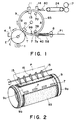
- Figure 1 is a sectional view of a color electrophotographic copying apparatus according to an embodiment of the present invention.
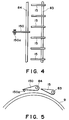
- Figure 2 is a perspective view of an example of an image transfer device.
- Figure 3 is a perspective view of a transfer device according to a second embodiment of the present invention, usable with an image forming apparatus according to this invention.
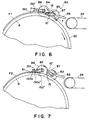
- Figure 4 is a top plan view of the device of Figure 3.
- Figure 5 is a side view of the device of Figure 3.
- Figure 6 is a side view illustrating separating means used in the transfer device of Figure 3.
- Figure 7 in a side view illustrating separating means used with the transfer device of Figure 3.
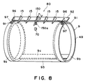
- Figure 8 is a perspective view of a transfer device according to a third embodiment of the present invention, usable with an image forming apparatus according to this invention.
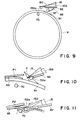
- Figure 9 is a side view illustrating separating means usable with the transfer device of Figure 8.
- Figure 10 is a side view illustrating the separating operation by the separating means usable with the transfer device of Figure 8.
- Figure 11 is a side view illustrating the separating operation of the separating means used in the transfer device of Figure 8.
- Figures 12, 13 and 14 are graphs showing relationships between the attraction force between the transfer material carrying sheet and the transfer material, and the transfer material thickness, the transfer current, the amount of toner.
- Figure 15 is a graph showing a relationship between the amount of the toner on the transfer material and the amount of oil on the transfer material.
- Figure 16 is a graph showing a relationship between a thickness of the transfer material and the amount of curling.
- Figure 17 is a graph showing a relationship between the amount of the toner on the transfer material and the amount of the curling of the transfer material.
- Figures 18 and 19 are graphs showing relationships between the transfer material attraction force of the transfer material carrying sheet and the curling amount of the transfer material or the amount of the deposited oil.
- Figures 20, 21 and 22 illustrates a relation between the transfer material and the image position formed thereon in a superposing or duplex print mode.
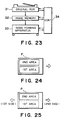
- Figure 23 is a control block diagram, according to an embodiment of the present invention.
- Figures 24 and 25 illustrate the positional relation between the image and the transfer material, when the present invention is used.
- Figure 26 is a flow chart of operations, according to a further embodiment of the present invention.
- FIG. 1 there is shown an electrophotographic color copying machine as an exemplary image forming apparatus according to an embodiment of the present invention.
- a recording material is carried on a recording material carrying member movable along an endless path, and the image transfer operations are repeated at an image transfer position so that a full-color image or a multi-color image is formed.
- the image forming process of the color electrophotographic machine will be briefly described.
- the copying machine comprises a photosensitive drum functioning as an electrostatic latent image bearing member.
- the photosensitive drum 3 rotates in a direction indicated by an arrow, and it is uniformly charged by a primary charger disposed adjacent to the photosensitive drum 3. Thereafter, it is exposed to image light at a position L, so that an electrostatic latent image is formed.
- the image is developed with toner.
- the transfer material P (recording material) is fed along a sheet feeding guide 58, and is gripped by a gripper 7 movable together with the transfer drum 9, with proper timing provided by registration rollers 6.
- the gripper 7 is effective to grip the transfer material P to carry it on the transfer drum 9.
- the gripper opens in the radial direction of the transfer drum 9 by an operation of a cam.
- the cam operates to close the gripper 7, so that the top side of the leading end of the transfer material P is confined by the gripping portion 7a of the gripper 7.
- This gripping structure is advantageous in that the carrying and separation of the transfer material relative to the transfer material carrying member are assured.
- This mechanism is particularly effective when the thickness of the transfer material is large (not less than 128 g/m 2 and not more than 180 g/m 2 , since such a transfer material has high resistivity.
- the mechanism is effective for the separation of the transfer material from the transfer material carrying member, since the rigidity of such a transfer material is low. This is because, when the gripper 7 opens, the lower side of the gripper confining the transfer material is raised, thus raising the leading edge.
- the first sheet is carried using the gripper 7, and the second sheet is carried on the surface of the transfer drum by electrostatic force.
- an attraction corona charger 39 is disposed at a position where the contact between the transfer material P and the surface of the transfer drum 9 starts, so that the electrostatic force is provided by the corona charger 39.
- the transfer drum 9 has a diameter of 160 mm, and is capable of carrying one A4 size transfer material P on area A and one A4 size transfer material P on B area in Figure 1.
- the shorter side of the A4 size transfer material is substantially parallel with the feeding direction of the transfer material.
- the transfer drum can carry two transfer materials thereon.
- the transfer material can carry only one transfer material.
- Figure 2 shows the separating action of the transfer material P which has been carried.
- dischargers 11 and 13 Figure 1
- the gripper 7 opens outwardly in the radial direction of the transfer drum 9 by the cam.
- the electrostatic attraction separation claws 15 are inserted to between the transfer material P and the dielectric sheet 93, so that the transfer material P is separated from the dielectric sheet 93.
- a pressing roller 70 is provided inside the dielectric sheet 93 to urge the dielectric sheet 93 outwardly.
- 5 - 9 separation claws 15 are provided, which are disposed at regular intervals and at the same angles, so that the separation claws provide the same separating function and effects.
- the separating timing comes, the separating claws 15 are contacting or moved toward the dielectric sheet 93 in response to a signal from control device (not shown).
- the transfer material P is separated from a dielectric sheet 93 and thereafter, with the completion of the separation, it is returned to the original position by the releasing signal from the control device.
- the transfer drum 9 comprises a metal frame including a pair of rings 9a and 9b and a connecting portion 9c for connecting the ring portions 9a and 9b, and the dielectric sheet 93 covering the cut-away portion defined by the rings and connecting portions.
- a plurality of grippers are mounted along the longitudinal direction of the connecting portion 9c. Therefore, the transfer material in the B area of the transfer drum of Figure 1 is not carried on the connecting portion 9c.
- the gap for permitting insertion of the separation claws between the dielectric sheet and the transfer material is narrow, and therefore, it is difficult for all of 5 - 9 separation claws are assuredly inserted.
- the separation claws When the separation claws are strongly urged to the dielectric sheet for the purpose of assuring the separation, the possibility of the damage of the dielectric sheet is increased with the result of more frequent replacements of the dielectric sheet. In view of this, the number of separation claws to be inserted first between the dielectric sheet and the transfer material is reduced to one, so that the gap for receiving the separation claws increases, thus reducing the possibility of the improper separation resulting from the number of separation claws.
- the separation would be possible. However, there are sufficient gaps for receiving 5 - 9 separation claws 15 shown in Figure 2. The possibility of the improper separation reduces when a plurality of separation claws are arranged in the direction of the width at regular intervals than when only one separation claw is used.
- the transfer material carrying means In order to separate the transfer material carried by the transfer material carrying means, the following is preferable.
- the plurality of separating members are inserted to between the transfer material and the recording material carrying member, and when the transfer material is carried by the electrostatic attraction means, a gap is formed at one position between the recording material and the recording material carrying member, and a first single separating member is inserted into the gap.
- a transfer material P1 is supplied to the transfer drum 9.
- the leading edge of the transfer material P1 is gripped by the gripper 7.
- the transfer material is moved toward the transfer position T by the rotation of the transfer drum 9.
- the fundamental operation of the gripper 7 in this case is the same as described hereinbefore, and therefore, the detailed description thereof is omitted for simplicity.
- the first transfer material P1 is gripped by the gripper 7 when the dimension of the transfer material P1 measured in the feeding direction is shorter than the circumferential direction of the dielectric sheet 93, and the dimension of the next transfer material P2 (not shown) measured in the same direction is the same as that of the transfer material P1, namely, when the transfer materials P1 and P2 can be carried on the A area and B area.
- the second transfer material P2 is attracted on the dielectric sheet 93 by the corona charger 39 and the attraction roller 40 disposed opposed thereto.
- the attraction means is disposed within the transfer drum 9, and is constituted by the attraction corona charger 39 for applying to the backside of the dielectric sheet 93 the electric charge of the polarity opposite from that of the toner image on the photosensitive drum 3, and the electrically conductive attraction roller 40 outside the transfer drum 9.
- the attraction roller 40 is electrically grounded to function as an opposite electrode for the attraction corona charger 39, and is effective to inject the electric charge to the transfer material P2 to attract the transfer material P2 onto the dielectric sheet 93.
- THe transfer materials P1 and P2 attracted on the transfer drum 9 is fed to the transfer position T where the transfer charger 10 is disposed.
- the transfer charger 10 in the form of a corona charger applies the electric charge of the polarity opposite from that of the toner to the backside of the dielectric sheet 93.
- the attraction roller 40 is separated from the transfer drum 9, and is moved away (not less than 2 mm) from the dielectric sheet so that it does not disturb the toner images transferred onto the transfer materials P1 and P2.
- an outside discharger 11 and an inside discharger 13 which constitute a pair of AC corona dischargers with the dielectric sheet 93 therebetween.
- the transfer materials P1 and P2 and the dielectric sheet 93 are electrically discharged.
- the separation means 80 including the separation claws 15 which will be described in detail hereinafter, the transfer material P is separated.
- the AC corona discharge is applied by the separation charger 14.
- the transfer materials P1 and P2 are fed to the fixing device 17 by a conveying device 24.
- the toner is mixed and fixed.
- the sheet is discharged, thus completing the copying operation.
- the transfer drum 9 comprises cylindrical rings 9a and 9b at the opposite ends and connecting portions 9c and 9d for connecting the rings 9a and 9b.
- the rings 9a and 9b and connecting portions 9c and 9d constitute a frame 49 for supporting a transfer material carrying member, that is, the dielectric sheet 93 made of dielectric film.
- the separating means 80 comprises separation claw supporting shafts 83 and 84 extended along the direction of the rotational axis of the transfer drum 9, 6 separation claws 15 on the shaft 83 and one separation claw 150 on the shaft 84.
- a guiding roller 150a may be provided integrally.
- a cut-away guiding groove 91 is formed to facilitate insertion of the edge of the separation claw 150 into the gap between the dielectric sheet 93 and the transfer material P electrostatically attracted on the dielectric sheet 93.
- the edge of the dielectric sheet 93 is bonded on the connecting portion 9c along a generating line passing through the cut-away guiding groove 91 of the connecting portion 9c, so that a seam is formed to the non-image region on the transfer material.
- the gear 87 is rotated in the direction of arrow by an unshown solenoid or the like to move the edge of the separation claws 15 toward the dielectric sheet 93 into the state indicated by 15' (solid line). By doing so, the edges of the separation claws 15 are inserted into the gap, so that the transfer material P1 is separated with the rotation of the transfer drum 9.
- the edge of the separating claw 150 is in the position indicated by a reference numeral 150', that is, away from the dielectric sheet 93.
- the gear 87 is rotated in the direction indicated by an arrow by an unshown solenoid or the like, as shown in Figure 7, by this, the gear 86 following the gear 87, rotates in the direction indicated by an arrow to place the edge of the separation claw 150 in the state indicated by a reference numeral 150" to urge the guiding roller 150a to the guiding groove 91.
- the edge of the separation claw 150 is inserted to between the transfer material P2 and the transfer drum 9, by which the transfer material 2 is separated from one point with the rotation of the transfer drum 9.
- the separation claw 150 is moved away upwardly to prevent interference with the transfer material P1, in Figure 6, so that the state indicated by the reference numeral 150' is established.
- the separation claws 15 are put into the state indicated by a reference numeral 15'' (solid line), by which the transfer material P2 is guided from the separation point to the guiding plate 88.
- FIG. 8 shows the separating means according to a third embodiment of the present invention.
- the transfer device comprises rings 9a and 9b and a connecting portion 9c with gripper for connecting the rings 9a and 9b.
- the rings 9a and 9b and the connecting portions 9c constitute a frame 49 for supporting a dielectric sheet 93 functioning as the transfer material carrying member.
- the separating means 80 comprises a separating claw supporting member 92 extended along an axis of the transfer drum 9, separating claws 15 and one separating claw 150, both on the supporting member 92.
- the edge of the single separating claw 150 is provided with an integral guiding roller 150a.
- the supporting member 92 is supported for vertical swinging of the separation claws 150 and the separation claw 150, by an unshown solenoid.
- abutment rollers 97 are provided at the opposite ends of the supporting member 92, using proper supporting plate 96.
- the abutment rollers 97 are contacted to the rings 9a and 9b of the transfer drum 9, when a separation clutch (not shown) is actuated. They are guided by the guiding grooves 91 formed in the rings 9a and 9b to rotate the edges of the separation claws 15 and the separation claw 50 downwardly, in the normal direction of the transfer drum 9.
- the rotating mechanism for the separation claws 15 and the separating claw 150 are not limited to this.
- a cam mechanism connected to the supporting plate 92 is usable.
- the abutment roller 70 in the transfer drum 9 abuts the inside of the dielectric sheet 93 by an unshown swinging means, as shown in Figure 11.
- the abutment roller 97 of the separating means is guided in the groove 91 at the opposite side of the connector 9c of the rings 9a and 9b, by which, the separation claw 150 swings to all the dielectric sheet 93.
- the separation claw 150 is advanced beyond the separating claws 15 by an unshown solenoid or the like.
- the guiding roller 150a integral with the separation claw 150 is urged from the outside to the dielectric sheet 93, thus changing the radius of curvature of the dielectric sheet at the location.
- the leading edge of the transfer material P2 is separated by the radius of curvature.
- the separation claw 150 and the separation claws 15 enter the gap between the transfer material P2 and the dielectric sheet 93, so that the transfer material P2 is separated.
- the separating claws are placed to the release position, and the inside roller 70 is moved away.
- the separation charger 14 Upon the separation of the transfer material P2, as shown in the Figure, the separation charger 14 is operated to effect the AC corona discharging preferably in order to prevent the disturbance to the image by separation discharge which may occur when the transfer material P and the dielectric sheet 93 are separated.
- the attraction and separation are carried out by the gripper, and therefore, the discrimination is made by using the sensor 99 disposed in the transfer drum 9 and at a position where the transfer material P approach the transfer drum 9, as shown in Figure 12, by which the roller 70 does not swing, and the separation claw 150 is not advanced forward.
- the image forming apparatus is a color image forming apparatus.
- the present invention is applicable to a monochromatic image forming apparatus having a transfer device.
- the recording material carrying member is not limited to a-cylindrical member, it may be in the form of a belt.
- the gripper When the gripper is used in the duplex mode (both side printing), the image positions on the first and second sides may be deviated from each other.
- the image if the image is formed and fixed on a first side, and then, it is refed for the purpose of superposing or duplex printing, the attraction of the transfer material onto the transfer drum is not stabilized with the result of deterioration of the image quality and the frequent occurrence of jam, since the degree of curling of the transfer material in large in the second image transfer and since the oil used in the first image fixing is deposited on the transfer material.
- the amount of toner is larger, and in particularly the color print toner is resin toner to provide clear color.
- the contraction rate of the toner is different from the transfer material, with the result of curling by the contraction rate difference. This is a cause of instability of the support of the transfer material on the transfer drum.
- the relation between the amount of the toner and the degree of the transfer material curling, and the relation between the degree of curling and the attraction to the transfer drum, are shown in Figures 17 and 18.
- the transfer material is supported, using a gripper, in the second and subsequent image formations.
- a gripper in the second and subsequent image formations.
- the image areas on the first side and the second side are deviated, as shown in Figures 20, 21 or 22.
- the transfer material is first supported without using the gripper and is second supported, using the gripper in the overlaying mode.
- the transfer material is first supported without using the gripper, and is secondary supported using the gripper in the duplex mode.
- the transfer material is firstly and secondly supported using the gripper in the duplex mode.
- the image area means the area in which the image is formable for given information. If the gripper is used at the first image formation, the position of the top margin of the image is reversed in the second image, as shown in Figure 22.
- control means is provided to control the position, size and the color so that the first side and the second side are aligned, in response to the image information reading and the output signal thereof.
- control means is provided to control the position, size and the color so that the first side and the second side are aligned, in response to the image information reading and the output signal thereof.
- the transfer material is fixed on the transfer material carrying sheet by electrostatic force or gripper, there are provided means for detecting the image information, the image formation mode and the material of the transfer sheet. On the basis of the outputs of these detecting means, the electrostatic force attraction or gripper support are selected on the basis of the outputs of the detecting means to support the transfer material on the transfer material carrying member in the second and subsequent image formation.
- Figure 23 is a block diagram of the apparatus of this embodiment.
- the image information of an original is read by a reader 31, and is stored in an image memory 32.
- a margin is provided in preparation for the gripping by the gripper in the second image formation at the leading end portion with respect to the feeding direction of the transfer material (white arrow), in the case of the overlaying or superimposing mode ( Figure 24).
- the margin is provided at the trailing edge portion ( Figure 25).
- the transfer material feeding direction is different between the first image transfer and the second image transfer, and therefore, the similar margins are provided for the first and side image formations for the transfer material.
- the width of the margin at the leading edge of the transfer material is larger than when the gripper is not used.
- the images can be correctly positioned in the overlaying and duplex mode. Since the length of the transfer material is changed by the image fixing operation for the first image formation, and since the coloring nature in the second image transfer is different from that in the first image formation, they are compensated for by the adjustment in the second image forming operation.
- electrostatic attraction force and the gripper are selectively usable as the means for supporting the transfer material on the transfer material carrying member.
- the electrostatic force acting on the transfer material carried on the transfer material carrying member changes depending on the following condition.
- the amount of the curl is determined by the thickness of the transfer material and the amount of the toner.
- the amount of the oil is determined by the toner amount. Therefore, if this is taken into account together with the sheet thickness influential to the attraction force, the toner amount, the oil amount or the like, the attraction force between the transfer material carrying member and the transfer material in the overlaying and duplex mode, is determined on the basis of the amount of image information on the first and second side, that is, the amount of the toner, the image formation mode, and the nature of the transfer material.
- an image forming apparatus in which the transfer material can be carried on the transfer material carrying member in good conditions.
- the image forming apparatus uses an automatic document feeder of circulation type in which one or more originals are stacked on the document feeder. The image forming number and the mode are set. It is discriminated whether or not the image is formed only on one side (S1). If only one side image formation (simplex mode), the operation proceeds to step S2, and the normal copying operation is carried out.
- the data is used which has been stored as to whether the attraction to the transfer material carrying member is difficult or not.
- the data are exchanged for the new cassette.
- the data are stored for the respective cassettes.
- the set image formation mode is used as the new data.
- step S4 the use of gripper is selected (step S4), and the image forming operation is carried out using the gripper.
- the similar discrimination is made on the basis of the material of the transfer sheet (S5). If it is a thick sheet, or if the curling amount will be a problem, the operation proceeds to S4 to use the gripper, and the image formation is carried out.
- the amount of image information (toner amount) is discriminated at step S7. If the non-use for the first and second side, is of no problem, the operation proceeds to steps S9 and S11 to effect the image forming operation. If the image information of the first side is large with the result of greater curling, or the oil amount by the first image information is large, or when the second side is monochromatic image resulting in smaller amount of toner, or the like, the attraction may be a problem in the second image formation. In such a case, the order of the first image information and the second image information is exchanged using the document circulation feeder. By doing so, the electrostatic attraction in the second image formation will not be a problem, and therefore, the operation proceeds through steps S6, S8 and S10 to step S9.
- step S6 when the electrostatic attraction on the second side is a problem irrespective of the order of image formations, the operations are carried out from step S6 to step S4 in the second image formation to use the gripper. If the use of gripper is quick as compared with the change of the order, the gripper is used in the second image forming operation.
Landscapes
- Physics & Mathematics (AREA)
- General Physics & Mathematics (AREA)
- Electrostatic Charge, Transfer And Separation In Electrography (AREA)
Claims (23)
- Bilderzeugungsvorrichtung, mitgekennzeichnet durcheinem Aufzeichnungsmaterial-haltenden Element (93) zum Halten eines Aufzeichnungsmaterials,einer Bilderzeugungseinrichtung zur Erzeugung eines Bilds auf dem Aufzeichnungsmaterial, das auf dem Aufzeichnungsmaterial-haltenden Element (93) gehalten wird, undeiner Anziehungseinrichtung (39, 40) zur Anziehung des Aufzeichnungsmaterials auf dem Aufzeichnungsmaterial-haltenden Element (93),eine Greifeinrichtung (7) zum Greifen eines Aufzeichnungsmaterials auf dem Aufzeichnungsmaterial-haltenden Element (93), bei welcher,wenn das Aufzeichnungsmaterial unbeschichtetes Papier ist, das Aufzeichnungsmaterial-haltende Element (93) dazu geeignet ist, gleichzeitig ein erstes und zweites Material (P1, P2) zu halten, und die Anziehungseinrichtung (39, 40) das erste oder zweite Material (P1, P2) auf dem Aufzeichnungsmaterial-haltenden Element (93) anzieht, ohne es mittels der Greifeinrichtung (7) zu greifen, während die Greifeinrichtung (7) das andere der Aufzeichnungsmaterialien (P1, P2) auf dem Aufzeichnungsmaterial-haltenden Element (93) greift, und,wenn das Aufzeichnungsmaterial dickes Papier ist, das eine zweite Dicke hat, welche größer als die des unbeschichteten Papiers ist, ein Aufzeichnungsmaterial auf dem Aufzeichnungsmaterial-haltenden Element (93) gehalten wird und mittels der Greifeinrichtung (7) gegriffen wird.
- Vorrichtung gemäß Anspruch 1, gekennzeichnet durch eine Trenneinrichtung (80) zur Trennung des Aufzeichnungsmaterials von dem Aufzeichnungsmaterial-haltenden Element (93), wobei die Trenneinrichtung (80) eine Vielzahl von Trennelementen (15), die bei der Trennung des mittels der Greifeinrichtung (7) gegriffenen Aufzeichnungsmaterials zuerst zwischen das Aufzeichnungsmaterial-haltende Element (93) und das Aufzeichnungsmaterial eingeführt werden, und ein einzelnes Trennelement (150) enthält, das bei der Trennung des nicht mittels der Greifeinrichtung (80) gegriffenen Aufzeichnungsmaterials zuerst zwischen das Aufzeichnungsmaterial-haltende Element (93) und das Aufzeichnungsmaterial eingeführt wird.
- Vorrichtung gemäß Anspruch 1, dadurch gekennzeichnet, daß die in eine Richtung der Bewegung des Aufzeichnungsmaterial-haltenden Elements (93) gemessenen Längen des ersten und zweiten Aufzeichnungsmaterials (P1, P2) kleiner als eine Hälfte der Umfangslänge des Aufzeichnungsmaterial-haltenden Elements (93) sind.
- Vorrichtung gemäß Anspruch 1, dadurch gekennzeichnet, daß das dicke Papier unabhängig von dessen Größe mittels der Greifeinrichtung (7) gegriffen wird.
- Vorrichtung gemäß Anspruch 1, dadurch gekennzeichnet, daß das erste Aufzeichnungsmaterial (P1) vor dem zweiten Aufzeichnungsmaterial (P2) auf dem Aufzeichnungsmaterial-haltenden Element (93) gehalten wird.
- Vorrichtung gemäß Anspruch 1, dadurch gekennzeichnet, daß das Aufzeichnungsmaterial, wenn das Aufzeichnungsmaterial unbeschichtetes Papier ist, mittels der Greifeinrichtung (7) gegriffen wird, wenn die in Richtung der Bewegung des Aufzeichnungsmaterial-haltenden Elements (93) gemessene Länge des Aufzeichnungsmaterials größer als eine Hälfte der Umfangslänge des Aufzeichnungsmaterial-haltenden Elements (93) ist.
- Vorrichtung gemäß Anspruch 1, dadurch gekennzeichnet, daß das Aufzeichnungsmaterial, wenn die in Richtung der Bewegung des Aufzeichnungsmaterial-haltenden Elements (93) gemessene Länge des Aufzeichnungsmaterials größer als eine Hälfte der Umfangslänge des Aufzeichnungsmaterial-haltenden Element (93) ist, unabhängig vom Material des Aufzeichnungsmaterials mittels der Greifeinrichtung (7) gegriffen wird.
- Vorrichtung gemäß Anspruch 1, dadurch gekennzeichnet, daßdie Vorrichtung dazu geeignet ist, ein Bild auf dem Aufzeichnungsmaterial auszubilden, auf welchem ein erstes Bild fixiert worden ist, und daßein Bereich des Aufzeichnungsmaterials, in welchem eine Bilderzeugung möglich ist, im wesentlichen zwischen einer ersten Bilderzeugung und einer zweiten Bilderzeugung ausgerichtet ist.
- Vorrichtung gemäß Anspruch 1, dadurch gekennzeichnet, daß die Vorrichtung dazu geeignet ist, ein Bild auf einer zweiten Seite des Aufzeichnungsmaterials auszubilden, nachdem ein Bild auf einer ersten Seite des Aufzeichnungsmaterials fixiert ist.
- Vorrichtung gemäß Anspruch 9, dadurch gekennzeichnet, daß Bereiche auf dem Aufzeichnungsmaterial, in welchen eine Bilderzeugung möglich ist, der ersten und zweiten Seite des Aufzeichnungsmaterials im wesentlichen ausgerichtet sind.
- Vorrichtung gemäß Anspruch 10, dadurch gekennzeichnet, daß das Aufzeichnungsmaterial, wenn ein Bild auf der zweiten Seite des Aufzeichnungsmaterials ausgebildet wird, mittels der Greifeinrichtung (7) gegriffen wird.
- Vorrichtung gemäß Anspruch 9, dadurch gekennzeichnet, daß, wenn ein Bild auf der ersten Seite des Aufzeichnungsmaterials ausgebildet wird, eine Breite eines rückwärtigen Rands des Aufzeichnungsmaterials größer als eine Breite eines vornliegenden Rands des Aufzeichnungsmaterials ist.
- Vorrichtung gemäß Anspruch 10, 11 oder 12, gekennzeichnet durch eine Speichereinrichtung (32) zur Speicherung von Bildinformation.
- Vorrichtung gemäß Anspruch 9, dadurch gekennzeichnet, daß das Aufzeichnungsmaterial bei der Bilderzeugung auf der zweiten Seite des Aufzeichnungsmaterials mittels der Greifeinrichtung (7) gegriffen werden kann.
- Vorrichtung gemäß Anspruch 14, dadurch gekennzeichnet, daß das Aufzeichnungsmaterial, wenn ein Bild auf der ersten Seite des Aufzeichnungsmaterials ausgebildet wird, mittels der Anziehungseinrichtung (14) angezogen werden kann.
- Vorrichtung gemäß Anspruch 9, dadurch gekennzeichnet, daß das Aufzeichnungsmaterial in Abhängigkeit von der Anzahl an Bilderzeugungen auf dem Aufzeichnungsmaterial bei der zweiten Bilderzeugung unter Nutzung der Greifeinrichtung (7) oder unter Nutzung der Anziehungseinrichtung (14) auf dem Aufzeichnungsmaterial-haltenden Element (93) gehalten wird.
- Vorrichtung gemäß Anspruch 9, dadurch gekennzeichnet, daßdie Bilderzeugungseinrichtung dazu geeignet ist, auf dem Aufzeichnungsmaterial ein Tonerbild auszubilden, unddas Aufzeichnungsmaterial in Abhängigkeit von einer Tonermenge des Tonerbilds wahlweise mittels der Greifeinrichtung (80) oder mittels der Anziehungseinrichtung (14) auf dem Aufzeichnungsmaterial-haltenden Element (93) gehalten wird.
- Vorrichtung gemäß Anspruch 9, dadurch gekennzeichnet, daß eine Reihenfolge der ersten und zweiten Bilderzeugung in Übereinstimmung mit einer auf dem Aufzeichnungsmaterial auszubildenden Bilderzeugung veränderbar ist.
- Vorrichtung gemäß Anspruch 9, dadurch gekennzeichnet, daß eine Reihenfolge der ersten und zweiten Bilderzeugung geändert wird, wobei das Aufzeichnungsmaterial bei der zweiten Bilderzeugung mittels der Anziehungseinrichtung (14) auf dem Aufzeichnungsmaterial-haltenden Element (93) gehalten wird.
- Vorrichtung gemäß Anspruch 1, dadurch gekennzeichnet, daß die Anziehungseinrichtung (14) das Aufzeichnungsmaterial auf elektrostatische Weise auf dem Aufzeichnungsmaterial-haltenden Element (93) anzieht.
- Vorrichtung gemäß Anspruch 1, dadurch gekennzeichnet, daß die Bilderzeugungseinrichtung aufweist,ein Bild-tragendes Element (3), auf welchem ein Tonerbild ausgebildet wird, undeine Übertragungseinrichtung (10) zur Übertragung des Tonerbilds von dem Bild-tragenden Element (3) auf das Aufzeichnungsmaterial, das auf dem Aufzeichnungsmaterial-haltenden Element (93) gehalten wird.
- Vorrichtung gemäß Anspruch 21, dadurch gekennzeichnet, daß eine Vielzahl derartiger Tonerbilder übereinanderliegend auf das auf dem Aufzeichnungsmaterial-haltenden Element (93) gehaltene Aufzeichnungsmaterial übertragen werden können.
- Vorrichtung gemäß Anspruch 22, dadurch gekennzeichnet, daß die Bilderzeugungsvorrichtung dazu geeignet ist, ein Vollfarbbild auf dem Aufzeichnungsmaterial auszubilden.
Applications Claiming Priority (4)
| Application Number | Priority Date | Filing Date | Title |
|---|---|---|---|
| JP30047592A JP3244544B2 (ja) | 1992-10-13 | 1992-10-13 | 画像形成装置 |
| JP300475/92 | 1992-10-13 | ||
| JP305879/92 | 1992-10-21 | ||
| JP30587992A JP3278702B2 (ja) | 1992-10-21 | 1992-10-21 | 画像形成装置 |
Publications (2)
| Publication Number | Publication Date |
|---|---|
| EP0593023A1 EP0593023A1 (de) | 1994-04-20 |
| EP0593023B1 true EP0593023B1 (de) | 1998-07-08 |
Family
ID=26562347
Family Applications (1)
| Application Number | Title | Priority Date | Filing Date |
|---|---|---|---|
| EP93116509A Expired - Lifetime EP0593023B1 (de) | 1992-10-13 | 1993-10-12 | Bilderzeugungsgerät mit Transportelement für Aufzeichnungsmaterial |
Country Status (3)
| Country | Link |
|---|---|
| US (1) | US5406358A (de) |
| EP (1) | EP0593023B1 (de) |
| DE (1) | DE69319532T2 (de) |
Families Citing this family (17)
| Publication number | Priority date | Publication date | Assignee | Title |
|---|---|---|---|---|
| JPH0830066A (ja) * | 1993-12-22 | 1996-02-02 | Canon Inc | 画像形成方法 |
| JPH07210015A (ja) * | 1994-01-11 | 1995-08-11 | Canon Inc | 画像形成装置 |
| JP3542371B2 (ja) * | 1994-01-24 | 2004-07-14 | キヤノン株式会社 | 画像形成装置 |
| JP3202868B2 (ja) * | 1994-03-30 | 2001-08-27 | キヤノン株式会社 | 画像形成装置 |
| US5585910A (en) * | 1994-07-27 | 1996-12-17 | Eastman Kodak Company | Image forming apparatus including relatively stiff receiving sheet control device |
| JP3303559B2 (ja) * | 1994-10-19 | 2002-07-22 | 富士ゼロックス株式会社 | 転写材検知装置 |
| JPH08171287A (ja) * | 1994-12-16 | 1996-07-02 | Fuji Xerox Co Ltd | 転写材検出装置 |
| JPH0916024A (ja) * | 1995-06-30 | 1997-01-17 | Minolta Co Ltd | 画像形成装置 |
| JP3823447B2 (ja) * | 1997-05-30 | 2006-09-20 | ブラザー工業株式会社 | 印刷装置 |
| JP3526226B2 (ja) | 1998-11-11 | 2004-05-10 | キヤノン株式会社 | シート処理装置及びこれを備える画像形成装置 |
| US6160981A (en) * | 1999-07-19 | 2000-12-12 | Xerox Corporation | Transfer system |
| US7463388B2 (en) * | 2003-05-29 | 2008-12-09 | Canon Kabushiki Kaisha | Image forming apparatus with control of image formation using read information |
| JP4185843B2 (ja) * | 2003-10-16 | 2008-11-26 | キヤノン株式会社 | シート処理システム |
| JP4272969B2 (ja) * | 2003-10-16 | 2009-06-03 | キヤノン株式会社 | シート処理システム |
| JP4732026B2 (ja) * | 2004-07-21 | 2011-07-27 | キヤノン株式会社 | シート後処理装置および画像形成装置 |
| CN101790486B (zh) * | 2007-08-31 | 2012-01-18 | 光荣株式会社 | 纸张厚度检测装置 |
| US8496246B2 (en) | 2007-08-31 | 2013-07-30 | Glory Ltd. | Thickness detector of paper |
Family Cites Families (10)
| Publication number | Priority date | Publication date | Assignee | Title |
|---|---|---|---|---|
| JPS6173976A (ja) * | 1984-09-19 | 1986-04-16 | Canon Inc | 転写装置 |
| JPS61138263A (ja) * | 1984-12-10 | 1986-06-25 | Canon Inc | 画像形成装置 |
| JP2556845B2 (ja) * | 1986-11-04 | 1996-11-27 | カヤバ工業株式会社 | 可変容量ポンプの出力制御装置 |
| JPS63177181A (ja) * | 1987-01-19 | 1988-07-21 | Canon Inc | シ−ト材担持装置 |
| JP2607117B2 (ja) * | 1988-04-05 | 1997-05-07 | キヤノン株式会社 | 画像形成装置 |
| JP2603120B2 (ja) * | 1988-12-09 | 1997-04-23 | キヤノン株式会社 | 画像形成装置 |
| JP2603133B2 (ja) * | 1989-05-31 | 1997-04-23 | キヤノン株式会社 | 画像形成装置 |
| JP2744315B2 (ja) * | 1990-02-06 | 1998-04-28 | キヤノン株式会社 | 画像形成装置 |
| JP2660939B2 (ja) * | 1990-10-11 | 1997-10-08 | キヤノン株式会社 | 画像形成装置 |
| JP3004239U (ja) | 1994-05-13 | 1994-11-08 | 勝徳 河合 | 動物用ブラシ |
-
1993
- 1993-10-12 EP EP93116509A patent/EP0593023B1/de not_active Expired - Lifetime
- 1993-10-12 DE DE69319532T patent/DE69319532T2/de not_active Expired - Fee Related
- 1993-10-13 US US08/134,653 patent/US5406358A/en not_active Expired - Fee Related
Also Published As
| Publication number | Publication date |
|---|---|
| EP0593023A1 (de) | 1994-04-20 |
| DE69319532D1 (de) | 1998-08-13 |
| DE69319532T2 (de) | 1999-01-28 |
| US5406358A (en) | 1995-04-11 |
Similar Documents
| Publication | Publication Date | Title |
|---|---|---|
| EP0593023B1 (de) | Bilderzeugungsgerät mit Transportelement für Aufzeichnungsmaterial | |
| EP0339309B1 (de) | Bilderzeugungsgerät | |
| US5168290A (en) | Image forming apparatus having recording material carrying means | |
| US5812923A (en) | Image forming apparatus equipped with register rollers for curling transfer paper | |
| EP0480454B1 (de) | Bilderzeugungsgerät | |
| EP0573061A2 (de) | Bilderzeugungsgerät | |
| US5440380A (en) | Imaging forming apparatus having transfer material carrying member for carrying transfer materials | |
| EP0720068A2 (de) | Bilderzeugungsgerät mit bewegbaren Band und Mittel um darauf Aufzeichnungsblätter zu positionieren | |
| JP2806956B2 (ja) | 多色像形成装置の運転方法 | |
| US6463247B1 (en) | Color image formation apparatus using plural photosensitive drums | |
| EP0480398B1 (de) | Bilderzeugungsgerät mit Aufzeichnungsmaterial-Transportmitteln | |
| EP0617341B1 (de) | Abstreifen von Papier von Photoleiterbändern mit reduzierter Beanspruchung | |
| JPH10115954A (ja) | 画像形成装置 | |
| JPH02502132A (ja) | 多色二重複写を行う静電写真法と装置 | |
| US20020001488A1 (en) | Color image forming apparatus | |
| JP3791588B2 (ja) | 画像形成装置 | |
| JP4018887B2 (ja) | 両面印刷記録装置 | |
| JP3347505B2 (ja) | 画像形成装置 | |
| JP3556410B2 (ja) | 静電画像形成方法 | |
| JP3643099B2 (ja) | 画像形成装置 | |
| JP2002019990A (ja) | シート搬送装置及びこれを備えた画像形成装置 | |
| JP3032596B2 (ja) | 画像形成装置 | |
| JPH07306618A (ja) | 画像形成装置 | |
| JP2002049254A (ja) | 画像形成装置 | |
| JPH08254927A (ja) | 電子写真装置 |
Legal Events
| Date | Code | Title | Description |
|---|---|---|---|
| PUAI | Public reference made under article 153(3) epc to a published international application that has entered the european phase |
Free format text: ORIGINAL CODE: 0009012 |
|
| 17P | Request for examination filed |
Effective date: 19931012 |
|
| AK | Designated contracting states |
Kind code of ref document: A1 Designated state(s): DE ES FR GB IT |
|
| 17Q | First examination report despatched |
Effective date: 19960206 |
|
| GRAG | Despatch of communication of intention to grant |
Free format text: ORIGINAL CODE: EPIDOS AGRA |
|
| GRAG | Despatch of communication of intention to grant |
Free format text: ORIGINAL CODE: EPIDOS AGRA |
|
| GRAG | Despatch of communication of intention to grant |
Free format text: ORIGINAL CODE: EPIDOS AGRA |
|
| GRAH | Despatch of communication of intention to grant a patent |
Free format text: ORIGINAL CODE: EPIDOS IGRA |
|
| GRAH | Despatch of communication of intention to grant a patent |
Free format text: ORIGINAL CODE: EPIDOS IGRA |
|
| GRAA | (expected) grant |
Free format text: ORIGINAL CODE: 0009210 |
|
| AK | Designated contracting states |
Kind code of ref document: B1 Designated state(s): DE ES FR GB IT |
|
| PG25 | Lapsed in a contracting state [announced via postgrant information from national office to epo] |
Ref country code: IT Free format text: LAPSE BECAUSE OF FAILURE TO SUBMIT A TRANSLATION OF THE DESCRIPTION OR TO PAY THE FEE WITHIN THE PRE;WARNING: LAPSES OF ITALIAN PATENTS WITH EFFECTIVE DATE BEFORE 2007 MAY HAVE OCCURRED AT ANY TIME BEFORE 2007. THE CORRECT EFFECTIVE DATE MAY BE DIFFERENT FROM THE ONE RECORDED.SCRIBED TIME-LIMIT Effective date: 19980708 Ref country code: ES Free format text: THE PATENT HAS BEEN ANNULLED BY A DECISION OF A NATIONAL AUTHORITY Effective date: 19980708 |
|
| REF | Corresponds to: |
Ref document number: 69319532 Country of ref document: DE Date of ref document: 19980813 |
|
| ET | Fr: translation filed | ||
| PLBE | No opposition filed within time limit |
Free format text: ORIGINAL CODE: 0009261 |
|
| STAA | Information on the status of an ep patent application or granted ep patent |
Free format text: STATUS: NO OPPOSITION FILED WITHIN TIME LIMIT |
|
| 26N | No opposition filed | ||
| REG | Reference to a national code |
Ref country code: GB Ref legal event code: IF02 |
|
| PGFP | Annual fee paid to national office [announced via postgrant information from national office to epo] |
Ref country code: DE Payment date: 20051006 Year of fee payment: 13 |
|
| PGFP | Annual fee paid to national office [announced via postgrant information from national office to epo] |
Ref country code: FR Payment date: 20051010 Year of fee payment: 13 |
|
| PGFP | Annual fee paid to national office [announced via postgrant information from national office to epo] |
Ref country code: GB Payment date: 20051012 Year of fee payment: 13 |
|
| PG25 | Lapsed in a contracting state [announced via postgrant information from national office to epo] |
Ref country code: DE Free format text: LAPSE BECAUSE OF NON-PAYMENT OF DUE FEES Effective date: 20070501 |
|
| GBPC | Gb: european patent ceased through non-payment of renewal fee |
Effective date: 20061012 |
|
| REG | Reference to a national code |
Ref country code: FR Ref legal event code: ST Effective date: 20070629 |
|
| PG25 | Lapsed in a contracting state [announced via postgrant information from national office to epo] |
Ref country code: GB Free format text: LAPSE BECAUSE OF NON-PAYMENT OF DUE FEES Effective date: 20061012 |
|
| PG25 | Lapsed in a contracting state [announced via postgrant information from national office to epo] |
Ref country code: FR Free format text: LAPSE BECAUSE OF NON-PAYMENT OF DUE FEES Effective date: 20061031 |