EP0593056B1 - Appareil d'enregistrement de signal d'information - Google Patents
Appareil d'enregistrement de signal d'information Download PDFInfo
- Publication number
- EP0593056B1 EP0593056B1 EP93116637A EP93116637A EP0593056B1 EP 0593056 B1 EP0593056 B1 EP 0593056B1 EP 93116637 A EP93116637 A EP 93116637A EP 93116637 A EP93116637 A EP 93116637A EP 0593056 B1 EP0593056 B1 EP 0593056B1
- Authority
- EP
- European Patent Office
- Prior art keywords
- signal
- track
- tracking
- recording
- signals
- Prior art date
- Legal status (The legal status is an assumption and is not a legal conclusion. Google has not performed a legal analysis and makes no representation as to the accuracy of the status listed.)
- Expired - Lifetime
Links
Images





Classifications
-
- G—PHYSICS
- G11—INFORMATION STORAGE
- G11B—INFORMATION STORAGE BASED ON RELATIVE MOVEMENT BETWEEN RECORD CARRIER AND TRANSDUCER
- G11B5/00—Recording by magnetisation or demagnetisation of a record carrier; Reproducing by magnetic means; Record carriers therefor
- G11B5/48—Disposition or mounting of heads or head supports relative to record carriers ; arrangements of heads, e.g. for scanning the record carrier to increase the relative speed
- G11B5/58—Disposition or mounting of heads or head supports relative to record carriers ; arrangements of heads, e.g. for scanning the record carrier to increase the relative speed with provision for moving the head for the purpose of maintaining alignment of the head relative to the record carrier during transducing operation, e.g. to compensate for surface irregularities of the latter or for track following
-
- G—PHYSICS
- G11—INFORMATION STORAGE
- G11B—INFORMATION STORAGE BASED ON RELATIVE MOVEMENT BETWEEN RECORD CARRIER AND TRANSDUCER
- G11B27/00—Editing; Indexing; Addressing; Timing or synchronising; Monitoring; Measuring tape travel
- G11B27/02—Editing, e.g. varying the order of information signals recorded on, or reproduced from, record carriers
- G11B27/031—Electronic editing of digitised analogue information signals, e.g. audio or video signals
- G11B27/036—Insert-editing
-
- G—PHYSICS
- G11—INFORMATION STORAGE
- G11B—INFORMATION STORAGE BASED ON RELATIVE MOVEMENT BETWEEN RECORD CARRIER AND TRANSDUCER
- G11B15/00—Driving, starting or stopping record carriers of filamentary or web form; Driving both such record carriers and heads; Guiding such record carriers or containers therefor; Control thereof; Control of operating function
- G11B15/18—Driving; Starting; Stopping; Arrangements for control or regulation thereof
- G11B15/1808—Driving of both record carrier and head
- G11B15/1875—Driving of both record carrier and head adaptations for special effects or editing
-
- G—PHYSICS
- G11—INFORMATION STORAGE
- G11B—INFORMATION STORAGE BASED ON RELATIVE MOVEMENT BETWEEN RECORD CARRIER AND TRANSDUCER
- G11B15/00—Driving, starting or stopping record carriers of filamentary or web form; Driving both such record carriers and heads; Guiding such record carriers or containers therefor; Control thereof; Control of operating function
- G11B15/18—Driving; Starting; Stopping; Arrangements for control or regulation thereof
- G11B15/46—Controlling, regulating, or indicating speed
- G11B15/467—Controlling, regulating, or indicating speed in arrangements for recording or reproducing wherein both record carriers and heads are driven
- G11B15/4673—Controlling, regulating, or indicating speed in arrangements for recording or reproducing wherein both record carriers and heads are driven by controlling the speed of the tape while the head is rotating
- G11B15/4675—Controlling, regulating, or indicating speed in arrangements for recording or reproducing wherein both record carriers and heads are driven by controlling the speed of the tape while the head is rotating with provision for information tracking
- G11B15/4676—Controlling, regulating, or indicating speed in arrangements for recording or reproducing wherein both record carriers and heads are driven by controlling the speed of the tape while the head is rotating with provision for information tracking using signals recorded in tracks disposed in parallel with the scanning direction
-
- G—PHYSICS
- G11—INFORMATION STORAGE
- G11B—INFORMATION STORAGE BASED ON RELATIVE MOVEMENT BETWEEN RECORD CARRIER AND TRANSDUCER
- G11B15/00—Driving, starting or stopping record carriers of filamentary or web form; Driving both such record carriers and heads; Guiding such record carriers or containers therefor; Control thereof; Control of operating function
- G11B15/18—Driving; Starting; Stopping; Arrangements for control or regulation thereof
- G11B15/46—Controlling, regulating, or indicating speed
- G11B15/467—Controlling, regulating, or indicating speed in arrangements for recording or reproducing wherein both record carriers and heads are driven
- G11B15/473—Controlling, regulating, or indicating speed in arrangements for recording or reproducing wherein both record carriers and heads are driven by controlling the speed of the heads
- G11B15/4731—Controlling, regulating, or indicating speed in arrangements for recording or reproducing wherein both record carriers and heads are driven by controlling the speed of the heads control of headwheel rotation
- G11B15/4733—Controlling, regulating, or indicating speed in arrangements for recording or reproducing wherein both record carriers and heads are driven by controlling the speed of the heads control of headwheel rotation with provision for information tracking, e.g. for time base correction
- G11B15/4735—Controlling, regulating, or indicating speed in arrangements for recording or reproducing wherein both record carriers and heads are driven by controlling the speed of the heads control of headwheel rotation with provision for information tracking, e.g. for time base correction using signals recorded in tracks disposed parallel with the scanning direction
-
- G—PHYSICS
- G11—INFORMATION STORAGE
- G11B—INFORMATION STORAGE BASED ON RELATIVE MOVEMENT BETWEEN RECORD CARRIER AND TRANSDUCER
- G11B2220/00—Record carriers by type
- G11B2220/90—Tape-like record carriers
-
- G—PHYSICS
- G11—INFORMATION STORAGE
- G11B—INFORMATION STORAGE BASED ON RELATIVE MOVEMENT BETWEEN RECORD CARRIER AND TRANSDUCER
- G11B27/00—Editing; Indexing; Addressing; Timing or synchronising; Monitoring; Measuring tape travel
- G11B27/02—Editing, e.g. varying the order of information signals recorded on, or reproduced from, record carriers
- G11B27/031—Electronic editing of digitised analogue information signals, e.g. audio or video signals
- G11B27/032—Electronic editing of digitised analogue information signals, e.g. audio or video signals on tapes
Definitions
- This invention relates to an information signal recording apparatus which employs a rotary magnetic head apparatus such as a video tape recorder.
- a video signal is recorded in oblique magnetic tracks on a magnetic tape by means of a rotary magnetic head apparatus.
- a single digital video signal is divided into a plurality of channels and recorded in independent tracks on a magnetic tape for the respective channels.
- FIGS. 7 to 9A to 9C illustrate an example of a manner in which a digital video signal is recorded divisionally in four A to D channels while a digital audio signal is recorded divisionally in a plurality of channels.
- a rotary magnetic head apparatus which includes magnetic heads 1A to 1D.
- the magnetic heads 1A and 1B are located on a head drum 2 in an angularly spaced relationship by a predetermined angle ⁇ and in a vertically offset relationship from each other while the other heads 1C and 1D are located on the head drum 2 similarly in an angularly spaced relationship by the predetermined angle ⁇ and in a vertical offset relationship from each other.
- the magnetic heads 1A and 1B and the magnetic heads 1C and 1D are located in an angularly spaced relationship by 180 degrees from each other.
- the heads 1A and 1C and the heads 1B and 1D have opposite azimuth angles relative to each other.
- the rotary magnetic head apparatus including the heads 1A to 1D is rotated in a field frequency in synchronism with an input video signal while a magnetic tape 3 is fed at a fixed speed obliquely along a circumferential face of the rotary magnetic head apparatus over an angular range greater than 180 degrees.
- tracking signals STA and STB are formed at or around a starting point of time of the former half TFR of each field period, and tracking signals STC and STD are formed at or around a starting point of the latter half TBK of each field period.
- the tracking signals STA to STD are supplied to the heads 1A to 1D, respectively. It is to be noted that the signals STA to STD are, for example, alternating signals which have a fixed level at a fixed frequency and have different frequencies from one another.
- an input stereo audio signal is converted from an analog signal into a digital signal and divided into four A to D channels, and encoding processing for error correction, time base compression and delaying processing and modulation processing for recording are performed for the digital audio signals of the A to D channels so as to make, for example, digital audio signals SSA to SSD at the positions following the signals STA to STD, respectively, as seen from FIG. 8B.
- the signals SSA to SSD are supplied to the heads 1A to 1D, respectively.
- an input video signal is converted from an analog signal into a digital signal and divided into four A to D channels, and encoding processing for error correction, time base compression and delaying processing and modulation processing for recording are performed for the video signals of the A to D channels so as to make for example, digital audio signals SVA to SVD at the positions following the signals SSA to SSD as seen from FIG. 8C.
- the signals SVA to SVD are supplied to the head 1A to 1D, respectively.
- the heads 1A and 1B scan the tape 2 obliquely and signals STA, SSA, SVA and STB, SSB, SVB are supplied to the heads 1A and 1B, respectively. Consequently, as shown in FIG. 9A, the signals STA and STB are recorded into track areas 4TA and 4TB at the top positions of two tracks 4, respectively, and then the signals SSA and SSB are recorded into track areas 4SA and 4SB at the positions following the track areas 4TA and 4TB of the two tracks 4, respectively. Finally, the signals SVA and SVB are recorded into track areas 4VA and 4VB at the positions following the track areas 4SA and 4SB of the two tracks 4, respectively.
- the heads 1C and 1D scan the tape 3 obliquely and signals STC, SSC, SVC and STD, SSD, SVD are supplied to the heads 1C and 1D, respectively. Consequently, as seen in FIG. 9B, the signals STC and STD are recorded into track areas 4TC and 4TD at the top positions of next two tracks 4, respectively, and then the signals SSC and SSD are recorded into track areas 4SC and 4SD at the positions following the track areas 4TC and 4TD of the tracks 4, respectively. Finally, the signals SVC and SVD are recorded into track areas 4VC and 4VD at the positions following the track areas 4SC and 4SD of the tracks 4, respectively.
- the angular distance ⁇ and the offset between the heads 1A and 1C and between the heads 1B and 1D and the feeding speed of the tape 3 are set in advance so that adjacent track areas (tracks) may be formed in a contiguous relationship to each other.
- a digital video signal can be digitally recorded by dividing it, for example, into four A to D channels in this manner.
- the track areas 4TA, 4SA and 4VA are portions of a single track formed by single scanning of the head 1A, and the widths and the positions of them in the widthwise direction are equal to each other. This similarly applies to all of the other track areas.
- the heads 1A to 1D can scan the tracks 4 regularly by performing tracking servoing using the track areas 4TA to 4TD.
- the positions of the track areas 4VA to 4VD or 4SA to 4SD to be formed in response to the new video signal or audio signal can be made coincide with the original track areas 4VA to 4VD or 4SA to 4SD.
- the non-recorded portions between the track areas 4SA to 4SD and 4VA to 4VD, that is, guard section, can be reduced sufficiently, thereby enhancing the rate of utilization of the tape 3.
- track areas 4TA, 4SA and 4VA when it is not necessary to distinct the track areas 4TA, 4SA and 4VA from each other, they are represented by the track 4A, and also the other track areas are represented by the track 4B, 4C or 4D.
- the track widths WTA to WTD of the tracks 4A to 4D are equal to a designed value WT0.
- the azimuth angles of the heads 1A to 1D are made so different as described above so that no guard band may be formed in the tracks 4 as seen in FIGS. 9A to 9C.
- the track widths WHA to WHD of the heads 1A to 1D are made greater than the track widths WTA to WTD of the tracks 4A to 4D so that edge portions of tracks formed by preceding or leading heads may be erased by following or trailing heads to adjust the track widths WTA to WTD of the tracks 4A to 4D to the designed value WTO.
- the track width WHB of the head 1B of the video tape recorder used for for editing is greater by 5 ⁇ m than the track width WTB of the track area 4TB of the tape 3.
- the width of 5 ⁇ m makes an insensitive zone in tracking servoing, and accordingly, tracking servoing becomes indefinite.
- the head 1B is within the range of (A) to (B) and (B) to (C) of FIG. 14 with respect to the track area 4TB, then it is considered that tracking is effective, and ⁇ 2.5 ⁇ m is the tracking accuracy then.
- the value of ⁇ 2.5 ⁇ m in tracking accuracy is a considerably dissatisfactory value.
- the errors of the track widths WTA to WTD of the tracks 4 are frequently increased by a temperature variation of the offsets HMA to HMD of the heads 1A to 1D, and in this instance, the difference value ⁇ is further increased, resulting in further degradation of the tracking accuracy.
- the object is achieved by means of the features of claim 1.
- Particular embodiments of the invention are specified in claims 2 to 12.
- the recording apparatus Even if the combination of the errors of the track widths of heads of the rotary magnetic head apparatus of a video tape recorder used for recording and the errors of the track widths of heads of the rotary magnetic head apparatus of another video tape recorder used for editing is in the worst, the accuracy in tracking servoing remains within the errors of the track widths.
- the accuracy of the track widths can be further enhanced, and consequently, the tracking accuracy can be further enhanced.
- track areas 4TA and 4TC for tracking are formed at top portions of every other ones 4A and 4C of tracks 4 while no track areas are formed at locations adjacent the track areas 4TA and 4TC by following or trailing heads.
- an information signal is first divided for each predetermined amount into four channels, and the information signals of the four channels are recorded in four oblique tracks 4A to 4D on a magnetic tape by means of four magnetic heads of a rotary magnetic head apparatus. Further, independently of the information signal, tracking signals STA and STC are recorded into particular areas 4TA and 4TC of every other ones 4A and 4C of the four magnetic tracks 4A to 4D at predetermined positions in the longitudinal direction of the tracks 4A and 4C.
- the areas 4TA and 4TC into which the tracking signals STA and STC are recorded are so positioned that, when the other ones 4B and 4D of the four magnetic tracks 4A to 4D are formed later, they are not formed at positions adjacent the areas 4TA and 4TC in which the tracking signals STA and STC are recorded.
- the track widths WTA and WTC (refer to FIG. 10) of the track areas 4TA and 4TC are equal to the track widths WHA and WHC (refer to FIG. 13) of the heads 1A and 1C, and consequently, the tracking accuracy remains within a tolerance of the track widths WHA and WHC of the heads 1A and 1C.
- FIGS. 1 and 2 there is shown a video tape recorder to which the present invention is applied. It is to be noted that FIG. 2 is contiguous at the top thereof to the bottom of FIG. 1.
- the video tape recorder includes a rotary magnetic head apparatus including magnetic heads 1A to 1D and a head drum 2 and having such a construction as described hereinabove with reference to FIG. 7.
- the rotary magnetic head apparatus is rotated, for example, in a field frequency by a motor 11.
- a magnetic tape 3 extends along and contacts with a circumferential face of the rotary magnetic head apparatus over an angular range greater than 180 degrees and is fed, upon recording, editing or reproduction, at a predetermined speed by a capstan 15 and a pinch roller 16.
- the video tape recorder further includes a timing signal formation circuit 22 to which a video signal, which makes a reference for synchronization such as a station synchronizing signal, is supplied by way of a terminal 21.
- the timing signal formation circuit 22 thus forms various timing signals and frequency signals as well as such a pulse signal P22 of a reference field period as seen, for example, in FIG. 3A.
- the video tape recorder further includes a recording control circuit 23 to which a mode signal MD representative of an operation mode such as a recording mode, an assemble editing mode or an insert editing mode from a system controller not shown. Operation of the formation circuit 22 and some other circuits is controlled in accordance with outputs of the control circuit 23.
- a mode signal MD representative of an operation mode such as a recording mode, an assemble editing mode or an insert editing mode from a system controller not shown. Operation of the formation circuit 22 and some other circuits is controlled in accordance with outputs of the control circuit 23.
- the video tape recorder further includes a drum servoing circuit 24 to which the pulse signal P22 is supplied from the formation circuit 22 and also a pulse signal representative of a phase in rotation of the rotary magnetic head apparatus, that is, the heads 1A to 1D, is supplied from a pulse generator 12 provided for the drum 2.
- the output of the servo circuit 24 is supplied to the motor 11. Consequently, upon recording, editing or reproduction, the phase in rotation of the heads 1A to 1D is servo controlled with reference to the pulse signal P22.
- the video tape recorder further includes a capstan servo circuit 25 to which an alternating signal of a predetermined frequency is supplied from the formation circuit 22 and also a signal of a frequency representative of the speed of rotation of the capstan 15 is supplied from a frequency generator 18 coupled in rotation to the capstan 15.
- the output of the servo circuit 25 is supplied to a capstan motor 17 so that the tape 3 is fed at a predetermined fixed speed upon recording or reproduction.
- the video tape recorder further includes a signal formation circuit 34 for forming a tracking signal, encoder circuits 42A to 42D for a digital audio signal, memory circuits 43A to 43D for performing time base compression and adjusting recording timings, and modulation circuits 44A to 44D for performing modulation for recording.
- the video tape recorder further includes encoders 52A to 52D for a digital video signal, memory circuits 53A to 53D for performing time base compression and adjusting recording timings, and modulation circuits 54A to 54D for performing modulation for recording.
- the video tape recorder further includes detection circuits 72A and 72C, amplitude detection circuits in this embodiment, for detecting the tracking signals and sampling hold circuits 73A and 73C.
- the following processing is performed upon ordinary recording, upon assemble editing and upon insert editing.
- control signals SWA to SWD of the "L" (low) level are taken out from the formation circuit 22, and switch circuits 63A to 63D are connected in such a condition as seen in FIG. 1 so that operation of recording amplifiers 62A to 62D is enabled in response to the control signals SWA to SWD, respectively, from the formation circuit 22.
- Another predetermined control signal is supplied from the formation circuit 22 to the tracking signal formation circuit 34. Consequently, the tracking signal formation circuit 34 forms a tracking signal STA, for example, as shown in FIG. 3B, within a period around a start point of the former half TFR of each field period and then forms another tracking signal STC within another period around a start point of the latter half TBK of the field period.
- the tracking signals STA and STC are supplied to OR circuits 61A and 61C, respectively.
- a digital stereo audio signal is supplied by way of a terminal 41 to the encoder circuits 42A to 42D, by which it is subsequently divided into signals SSA to SSD of four A to D channels and encoding processing for error correction is performed for the signals SSA to SSD. Thereafter, the signals SSA to SSD are written into the memory circuits 43A to 43D, respectively.
- Read-out of the memory circuits 43A to 43D is controlled by a signal from the formation circuit 22 such that, as seen from FIG. 3C, of the signals SSA to SSD written in the memory circuits 43A to 43D, the signals SSA and SSB of the A and B channels are read out in a time base compressed condition within a period following the tracking signal STA, and then the signals SSC and SSD of the C and D channels are read out similarly in a time base compressed condition within another period following the tracking signal STC.
- the signals SSA to SSD read out in this manner are supplied to the modulation circuits 44A to 44D, respectively, in which modulation processing for recording is performed subsequently.
- the signals SSA to SSD, for which such modulation processing has been performed, are supplied to the OR circuits 61A to 61D, respectively.
- a digital video signal is supplied by way of another terminal 51 to the encoder circuits 52A to 52D, in which it is subsequently divided into signals SVA to SVD of the four A to D channels and encoding processing for error correction is performed for the signals SVA to SVD, respectively. Thereafter, the signals SVA to SVD are written into the memory circuits 53A to 53D, respectively.
- Read-out of the memory circuits 53A to 53D is controlled by a signal from the formation circuit 22 such that, as seen from FIG. 3D, of the signals SVA to SVD written in the memory circuits 53A to 53D, the signals SVA and SVB of the A and B channels are read out in a time base compressed condition within a period following the digital audio signals SSA and SSB, and then the signals SVC and SVD of the C and D channels are read out similarly in a time base compressed condition within another period following the the digital audio signals SSC and SSD.
- the signals SVA to SVD read out in this manner are supplied to the modulation circuits 54A to 54D, respectively, in which modulation processing for recording is performed subsequently.
- the signals SVA to SVD, for which such modulation processing has been performed, are supplied to the OR circuits 61A to 61D, respectively.
- signals SRA to SRD for which such recording processing as described above has been performed, are outputted at such timings as seen in FIG. 3E.
- the tracking signal STA, the digital audio signal SSA of the A channel and the digital video signal SVA of the A channel are successively extracted as its output signal SRA within the former half period TFR
- the OR circuit 61B the digital audio signal SSB of the B channel and the digital video signal SVB of the B channel are successively extracted within a period of the former half period TFR following the tracking signal STA.
- the tracking signal STC, the digital audio signal SSC of the C channel and the digital video signal SVC of the C channel are successively extracted as its output signal SRC within the latter half period TBK
- the digital audio signal SSD of the D channel and the digital video signal SVD of the D channel are successively extracted as its output signal SRD within a period of the latter half period TBK following the tracking signal STC.
- the signals SRA to SRD are supplied to the rotary heads 1A to 1D by way of the recording amplifiers 62A to 62D and the switch circuits 63A to 63D, respectively.
- tracks 4 are formed at the ratio of one set for each one field on the tape 3 as shown in FIG. 5.
- the signals STA, SSA and SVA of the signal SRA are recorded in track areas 4TA, 4SA and 4VA, respectively of a corresponding one of the tracks 4 by the head 1A while at the same time the signals SSB and the SVB of the signal SRB are recorded in track areas 4SB and 4VB, respectively, of another corresponding one of the tracks 4 by the head 1B.
- the signals STC, SSC and SVC of the signal SRC are recorded in track areas 4TC, 4SC and 4VC, respectively, of a further corresponding one of the tracks 4 while at the same time the signals SSD and SVD of the signal SRD are recorded in track areas 4SD and 4VD, respectively, of the remaining one of the tracks by the head 1D.
- the track areas 4TA and 4TC are formed in the corresponding two tracks 4, but since no tracking signals are supplied to the heads 1B and 1D, track areas (track areas 4TB and 4TC of FIG. 9) corresponding to the track areas 4TA and 4TC are not formed. Consequently, the corresponding end portions of the track areas 4TA and 4TC are not erased by overwriting, and accordingly, the track widths WTA and WTC of the track areas 4TA and 4TC remain equal to the track widths WHA and WHC of the heads 1A and 1C which have formed the track areas 4TA and 4TC, respectively.
- the tape 3 is rewound, for example, for 3 minutes from an editing start point, and then, the video tape recorder is put into a reproduction condition from the thus rewound point.
- operation of the recording amplifiers 62A to 62D is inhibited in accordance with a control signal from the formation circuit 22.
- signals are reproduced from the tracks 4A to 4D by the heads 1A to 1D, respectively.
- the tracking signals STA and STC are reproduced first from the track areas 4TA and 4TC by the heads 1A and 1C, respectively, and then, the signals SSA and SSC are reproduced form the track areas 4SA and 4SC, respectively, whereafter the signals SVA and SVC are reproduced from the track areas 4VA and 4VC, respectively.
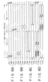
- the control signals SWA and SWC from the formation circuit 22 are changed over to the "H" (high) level corresponding to the tracking signals STA and STC as seen in FIG. 4C (FIGS. 4A and 4B are the same as FIGS. 3A and 3B, respectively), and the signals SWA and SWC are supplied to the switch circuits 63A and 63C, respectively.
- SWA and SWC "H”
- the switch circuits 63A and 63C are connected in a condition reverse to that shown in FIG. 1.
- the signals SWB and SWD remain at the "L" (low) level, and consequently, the switch circuits 63B and 63D remain in the connection condition shown in FIG. 1.
- the tracking signals STA and STC are extracted by way of the switch circuits 63A and 63C and supplied by way of reproduction amplifiers 71A and 71C to amplitude detection circuits 72A and 72C, by which the tracking signals STA and STC are detected by amplitude detection, respectively. Consequently, signals SPA and SPC representative of reproduction levels of the signals STA and STC are extracted from the detection circuit 72A and 72C, respectively.
- the signals SPA and SPC are supplied to sampling hold circuits 73A and 73C so that the levels of the signals SPA and SPC are sampled and held by the sampling hold circuits 73A and 73C, respectively, in accordance with a control signal from the formation circuit 22. Consequently, signals SLA and SLC representative of the levels of the reproduced tracking signals SSA and SSC are extracted from the sampling hold circuits 73A and 73C, respectively.
- the signals SLA and SLC are supplied to and added to each other by an addition circuit 74, and the addition signal of the addition circuit 74 is supplied to a servo circuit 25. Consequently, feeding of the tape 3 is servo controlled in response to the addition signal by the servo circuit 25 so that the levels of the tracking signals STA and STC reproduced from the track areas 4TA and 4TC may exhibit their maximum levels, respectively.
- the formation circuit 22 is controlled by the control circuit 23 so that the signals SWA to SWD are changed over to the "L" level. Consequently, the switch circuits 63A to 63D are changed over to the connection condition shown in FIG. 1. Further, recording signals SRA to SRD are formed by the circuits 34 and 42A to 61D in a similar manner as upon ordinary recording described above, and operation of the amplifiers 62A to 62D is enabled.
- the tracks 4 in which the new signals are recorded are formed with reference to the positions of the old tracks 4 just prior to the editing start point. Accordingly, at the editing start point, new recording is started without any disorder of the periodicity of the tracks 4, and consequently, assemble editing is performed.
- the control signals SWA and SWC are changed over to the "H" level at the same timings as the tracking signals STA and STC as seen in FIG. 4C, respectively.
- the signals SWA and SWC are supplied to the switch circuits 63A and 63C so that, when the signals SWA and SWC are at the "H" level, the switch circuits 63A and 63C are connected in the reverse condition to that shown in FIG. 1. It is to be noted that the signals SWB and SWD remain at the "L" level, and consequently, the switch circuits 63B and 63D remain in the connection condition shown in FIG. 1.
- the tracking signals STA and STC are reproduced from the track areas 4TA and 4TC while tracking servoing is performed by the servo circuit 25 so that the levels of the tracking signals STA and STC may present their maximum levels, respectively.
- recording signals SRA to SRD are formed by the circuits 42A to 61D in a similar manner as upon ordinary recording described above, and operation of the amplifiers 62A to 62D is enabled. In this instance, however, formation of tracking signals STA and STC by the formation circuit 34 is not performed, and accordingly, no tracking signals STA and STC are included in the signals SRA and SRC, respectively.
- the signals SRA to SRD include digital audio signals SSA to SSD and digital video signals SVA to SVD as seen in FIG. 3E.
- the signals SRA to SRD are supplied to the heads 1A to 1D by way of the amplifiers 62A to 62D and the switch circuits 63A to 63D, respectively.
- the heads 1A to 1D are controlled by tracking servoing to the track areas 4TA and 4TC which were recorded in the past.
- the new digital audio signal and the new digital video signal are recorded with reference to the positions of the formerly recorded track areas 4TA and 4TC from the editing start point.
- new recording is performed without any disorder in periodicity of the tracks 4 at the editing start point, and consequently, insert editing of the digital audio signal and the digital video signal is performed.
- the new digital audio signal or digital video signal is recorded with reference to the positions of the formerly recorded track areas 4TA and 4TC from the editing start point, and only the digital audio signal or digital video signal is recorded by insert editing.
- Assemble editing and insert editing are individually performed in such manners as described above.
- such track areas 4TB and 4TD as shown in FIG. 9 are not formed adjacent the track areas 4TA and 4TC. Accordingly, edge portions of the track areas 4TA and 4TC are not erased by overwriting of adjacent track areas, and consequently, the track widths WTA and WTC of the track areas 4TA and 4TC remain equal to the track widths WHA and WHC of the heads 1A and 1C upon recording.
- the tracking accuracy is ⁇ 1 ⁇ m at the editing start point.
- the track width WHA of the head 1A of another video tape recorder used for editing is given by the equation (12) above.
- the track width WHA WH0 - 1 ⁇ m
- the track width WHA of the head 1A of the video tape recorder used for recording is increased by only 2 ⁇ m than the recorded track area 4TA.
- the insensitive band in tracking servoing is 2 ⁇ m in width, and the tracking accuracy of ⁇ 1 ⁇ m can be assured.
- the tracking accuracy in this instance is ⁇ 1 ⁇ m.
- the heads 1A to 1D are formed as thin film heads, the accuracy of the track widths WHA to WHD is further enhanced, and consequently, the tracking accuracy can be further enhanced.
- track areas (4TA and 4TC) for tracking are formed only for the tracks 4A and 4C, they may alternatively be formed (as track areas 4TA to 4TD for tracking) for all of the tracks 4A to 4D.
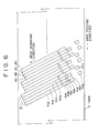
- the track areas 4TA and 4TC should be displaced in the longitudinal direction of the tracks 4 from the track areas 4TB and 4TD, for example, as seen in FIG. 6 so that another track area may not be formed later on either side of each of the track areas 4TA to 4TD.
- the track areas 4TA and 4TC are formed on the starting or leading sides of the tracks 4A and 4C
- such track areas 4TA and 4TC or the track areas 4TB and 4TD may be formed at some other locations of the corresponding tracks 4 such as, for example, at the trailing end positions of the corresponding tracks 4.
- the signals STA and STC to be recorded in the track areas 4TA and 4TC may be of some other format only if they can be used as detection signals for a tracking error.
Landscapes
- Engineering & Computer Science (AREA)
- Multimedia (AREA)
- Signal Processing (AREA)
- Signal Processing For Digital Recording And Reproducing (AREA)
- Management Or Editing Of Information On Record Carriers (AREA)
Claims (12)
- Un appareil d'enregistrement dans lequel des pistes obliques sont formées sur une bande au moyen d'une structure de têtes tournantes, pour enregistrer un signal d'information dans les pistes obliques (4A, 4B, 4C, 4D), cet appareil d'enregistrement ayant un mode d'enregistrement ordinaire et un mode de montage dans lequel le signal d'information est enregistré en supplément sur la bande (3) sur laquelle des pistes obliques (4A, 4B, 4C, 4D) ont déjà été formées,
caractérisé en ce quel'appareil d'enregistrement comprend des moyens pour former une zone de piste (4TA, 4TC) pour le suivi de piste, dans une zone située à une position prédéterminée de l'une sur deux (4A, 4C) des pistes obliques (4A, 4B, 4C, 4D), dans une direction longitudinale de la piste (4A, 4C), au moyen d'une tête (1A, 1B, 1C, 1D) de la structure de têtes tournantes, et pour empêcher qu'une autre tête suivante (1A, 1B, 1C, 1D) de la structure de têtes tournantes forme une autre zone de piste à une position correspondante de la piste oblique adjacente suivante (4B, 4D), adjacente à la zone de piste (4TA, 4TC). - Un appareil d'enregistrement selon la revendication 1, dans lequel un signal de suivi de piste est enregistré dans la zone de piste (4TA, 4TC) indépendamment du signal d'information.
- Un appareil d'enregistrement selon la revendication 1 ou 2, comprenant :un circuit de commande d'enregistrement (23) pour recevoir un signal de mode représentatif d'un mode de fonctionnement de l'appareil d'enregistrement;un circuit de génération de signaux de temps (22) pour générer plusieurs signaux de temps et de fréquence à partir du signal d'information;un circuit d'asservissement de tambour (24) pour commander la phase de rotation de la structure de têtes tournantes;un circuit d'asservissement de cabestan (25) pour commander la vitesse d'entraínement de la bande; etun circuit de génération de signal de suivi de piste (63A-D, 71A-73A, 71C-73C, 74) pour générer un signal de suivi de piste.
- Un appareil d'enregistrement selon la revendication 3, dans lequel, lorsque l'appareil d'enregistrement est dans le mode d'enregistrement ordinaire, le circuit de génération de signaux de temps (22) fait en sorte que la structure de têtes magnétiques tournantes, sous la commande du circuit de commande d'enregistrement (23), enregistre le signal d'information et le signal de suivi de piste qui est généré par le circuit de génération de signal de suivi de piste (22), de manière que le signal de suivi de piste soit enregistré dans une première zone (4TA, 4TC) à une position prédéterminée dans une direction longitudinale d'au moins une piste particulière parmi chacune de N pistes obliques (4A, 4C), indépendamment du signal d'information, mais que le signal de suivi de piste ne soit pas enregistré ultérieurement dans une autre zone adjacente à la première zone (4TA, 4TC) et à une position dans une direction longitudinale de l'une quelconque des N pistes obliques (4B, 4D) se trouvant d'un côté ou de l'autre de la piste particulière, N étant un nombre entier supérieur ou égal à 2.
- Un appareil d'enregistrement selon la revendication 3, dans lequel, lorsque l'appareil d'enregistrement est dans un mode de montage, le circuit de génération de signaux de temps (22) fait en sorte que le circuit d'asservissement de cabestan (25) et la structure de têtes magnétiques tournantes, sous la commande du circuit de commande d'enregistrement (23), fonctionnent d'une manière telle que la bande soit tout d'abord entraínée dans la direction arrière sur une distance prédéterminée, à partir d'une position prédéterminée de la bande, et soit ensuite entraínée dans la direction avant, et que de l'information qui est enregistrée sur les pistes obliques (4A, 4B, 4C, 4D) soit lue par la structure de têtes magnétiques tournantes pour détecter un signal de suivi de piste, et ensuite, après que la position prédéterminée de la bande (3) a été atteinte, il fait en sorte que la structure de têtes magnétiques tournantes enregistre le signal d'information et le signal de suivi de piste qui est généré par le circuit de génération de signal de suivi de piste (22), de façon que le signal de suivi de piste soit enregistré dans une première zone (4TA, 4TC) à une position prédéterminée dans une direction longitudinale d'au moins une piste particulière parmi chacune de N pistes obliques (4A, 4C), indépendamment du signal d'information, mais que le signal de suivi de piste ne soit pas enregistré ultérieurement dans une autre zone adjacente à la première zone (4TA, 4TC) et à une position dans une direction longitudinale de l'une quelconque des N pistes obliques (4B, 4D), d'un côté ou de l'autre de la piste particulière, N étant un nombre entier supérieur ou égal à 2.
- Un appareil d'enregistrement selon l'une quelconques des revendications 3 à 5, dans lequel, lorsque l'appareil d'enregistrement est dans un mode de montage, le circuit de génération de signaux de temps (22) fait en sorte que le circuit d'asservissement de cabestan (25) et la structure de têtes magnétiques tournantes, sous la commande du circuit de commande d'enregistrement (23), fonctionnent de façon que la bande (3) soit tout d'abord entraínée dans la direction arrière, sur une distance prédéterminée, à partir d'une position prédéterminée de la bande, et soit ensuite entraínée dans la direction avant, et que de l'information qui est enregistrée sur les pistes obliques (4A, 4B, 4C, 4D) soit lue par la structure de têtes magnétiques tournantes, pour détecter un signal de suivi de piste, et ensuite, après que la position prédéterminée de la bande (3) a été atteinte, il fait en sorte que la structure de têtes magnétiques tournantes enregistre le signal d'information.
- Un appareil d'enregistrement selon l'une quelconques des revendications 3 à 6, dans lequel le circuit de génération de signaux de temps (22) forme un signal impulsionnel de référence d'une période de trame.
- Un appareil d'enregistrement selon l'une quelconques des revendications 3 à 7, dans lequel le circuit de génération de signaux de temps (22) est commandé par le circuit de commande d'enregistrement (23).
- Un appareil d'enregistrement selon l'une quelconques des revendications 3 à 8, dans lequel le circuit d'asservissement de tambour (63A-D, 71A-73A, 71C-73C, 74) reçoit un signal de phase de rotation de la structure de têtes tournantes et il commande la phase de rotation de la structure de têtes tournantes par référence à un signal impulsionnel de référence qui est reçu à partir du circuit de génération de signaux de temps (22).
- Un appareil d'enregistrement selon l'une quelconques des revendications 3 à 9, dans lequel le circuit d'asservissement de cabestan (25) reçoit un signal représentatif d'une vitesse de rotation d'un cabestan (15) et il commande la phase de rotation du cabestan (15) par référence à un signal impulsionnel de référence qui est reçu à partir du circuit de génération de signaux de temps (22).
- Un appareil d'enregistrement selon l'une quelconques des revendications 3 à 10, dans lequel le signal de mode est reçu à partir d'une unité de commande de système et représente l'un des modes de fonctionnement comprenant un mode d'enregistrement, un mode de montage par assemblage et un mode de montage par insertion.
- Un appareil d'enregistrement selon la revendication 1, comprenant :la structure de têtes magnétiques tournantes enregistrant les signaux d'information des N canaux dans N pistes magnétiques (4A, 4B, 4C, 4D) sur une bande magnétique (3); etdes moyens (42A-42D, 52A-52D) pour diviser en N canaux le signal d'information correspondant à chaque intervalle prédéterminé, N étant un nombre entier supérieur ou égal à 2;des moyens pour faire en sorte que la structure de têtes tournantes enregistre des signaux de suivi de piste dans des zones (4TA, 4TC) à des positions prédéterminées dans des directions longitudinales des N pistes magnétiques (4A, 4C), indépendamment des signaux d'information, les zones étant placées de façon qu'aucune piste magnétique ne puisse être enregistrée dans une position adjacente à chacune des zones (4A, 4C) dans lesquelles les signaux de suivi de piste sont enregistrés.
Applications Claiming Priority (2)
| Application Number | Priority Date | Filing Date | Title |
|---|---|---|---|
| JP301754/92 | 1992-10-14 | ||
| JP4301754A JPH06131821A (ja) | 1992-10-14 | 1992-10-14 | 情報信号の記録装置 |
Publications (3)
| Publication Number | Publication Date |
|---|---|
| EP0593056A2 EP0593056A2 (fr) | 1994-04-20 |
| EP0593056A3 EP0593056A3 (en) | 1995-10-04 |
| EP0593056B1 true EP0593056B1 (fr) | 1998-06-10 |
Family
ID=17900767
Family Applications (1)
| Application Number | Title | Priority Date | Filing Date |
|---|---|---|---|
| EP93116637A Expired - Lifetime EP0593056B1 (fr) | 1992-10-14 | 1993-10-14 | Appareil d'enregistrement de signal d'information |
Country Status (5)
| Country | Link |
|---|---|
| US (1) | US5410435A (fr) |
| EP (1) | EP0593056B1 (fr) |
| JP (1) | JPH06131821A (fr) |
| KR (1) | KR100265906B1 (fr) |
| DE (1) | DE69319055T2 (fr) |
Families Citing this family (6)
| Publication number | Priority date | Publication date | Assignee | Title |
|---|---|---|---|---|
| CN1060905C (zh) * | 1993-02-26 | 2001-01-17 | 三星电子株式会社 | 用于盒式磁带录像机音频信号的记录格式、方法及装置 |
| JPH08147611A (ja) * | 1994-11-25 | 1996-06-07 | Hitachi Ltd | 磁気記録再生方法および磁気記録再生装置 |
| US6603618B1 (en) * | 1998-11-16 | 2003-08-05 | Exabyte Corporation | Method and system for monitoring and adjusting tape position using control data packets |
| TW484146B (en) * | 2000-12-30 | 2002-04-21 | Polytronics Technology Corp | Excess current protection device and method of manufacturing the same |
| KR100486497B1 (ko) * | 2002-08-13 | 2005-04-29 | 엘지전자 주식회사 | 히터 내장형 감습센서 및 그 제조방법 |
| US7570591B2 (en) * | 2004-08-03 | 2009-08-04 | Hewlett Packard Development Company, L.P. | Method and apparatus for negotiating link speed and configuration |
Family Cites Families (8)
| Publication number | Priority date | Publication date | Assignee | Title |
|---|---|---|---|---|
| JPS5897737U (ja) * | 1981-12-22 | 1983-07-02 | 日本ビクター株式会社 | 磁気記録再生装置 |
| JPH0666096B2 (ja) * | 1984-07-27 | 1994-08-24 | 株式会社日立製作所 | 磁気記録再生装置 |
| JPH01107355A (ja) * | 1987-10-21 | 1989-04-25 | Canon Inc | トラッキング方式 |
| JPH0792885B2 (ja) * | 1988-05-16 | 1995-10-09 | 日本ビクター株式会社 | 磁気記録再生装置 |
| JPH0426947A (ja) * | 1990-05-21 | 1992-01-30 | Sony Corp | 再生方法 |
| JPH04195844A (ja) * | 1990-11-27 | 1992-07-15 | Sony Corp | 記録装置 |
| JP2947297B2 (ja) * | 1991-02-08 | 1999-09-13 | ソニー株式会社 | 磁気記録装置 |
| US5313338A (en) * | 1991-04-11 | 1994-05-17 | Matsushita Electric Industrial Co., Ltd. | Editing device which selectively edits a section of a helical track |
-
1992
- 1992-10-14 JP JP4301754A patent/JPH06131821A/ja active Pending
-
1993
- 1993-10-12 US US08/133,843 patent/US5410435A/en not_active Expired - Lifetime
- 1993-10-14 DE DE69319055T patent/DE69319055T2/de not_active Expired - Lifetime
- 1993-10-14 KR KR1019930021255A patent/KR100265906B1/ko not_active Expired - Fee Related
- 1993-10-14 EP EP93116637A patent/EP0593056B1/fr not_active Expired - Lifetime
Also Published As
| Publication number | Publication date |
|---|---|
| US5410435A (en) | 1995-04-25 |
| KR940009955A (ko) | 1994-05-24 |
| DE69319055D1 (de) | 1998-07-16 |
| EP0593056A3 (en) | 1995-10-04 |
| DE69319055T2 (de) | 1998-10-29 |
| JPH06131821A (ja) | 1994-05-13 |
| EP0593056A2 (fr) | 1994-04-20 |
| KR100265906B1 (ko) | 2000-09-15 |
Similar Documents
| Publication | Publication Date | Title |
|---|---|---|
| EP0080297B1 (fr) | Arrangement d'enregistrement et de reproduction sur bande magnétique | |
| EP0117753A2 (fr) | Méthode et dispositif pour enregistrer des signaux numériques d'information | |
| EP0352980B1 (fr) | Contrôle de têtes pour un suivi dynamique de piste pour un magnétoscope | |
| EP0209047B1 (fr) | Appareil pour enregistrer et/ou reproduire un signal d'information | |
| EP0380284B1 (fr) | Appareil et procédé de production de signaux de commande de suivi de piste | |
| US5233488A (en) | Method and apparatus for detecting tracking errors | |
| EP0593056B1 (fr) | Appareil d'enregistrement de signal d'information | |
| US5051846A (en) | Magnetic video tape recording and reproducing apparatus | |
| US5459617A (en) | Apparatus and methods for recording information signals and tracking signals on magnetic tape | |
| EP0560596A2 (fr) | Appareil d'enregistrement et de reproduction magnétique amélioré utilisant un système d'enregistrement par segments | |
| JP3271103B2 (ja) | 回転ヘッド型記録/再生装置 | |
| EP0393995A2 (fr) | Systèmes automatiques de suivi de piste pour appareils d'enregistrement et/ou de reproduction magnétique | |
| US6026214A (en) | Digital video recording apparatus and method | |
| EP0532323B1 (fr) | Appareil numérique d'enregistrement de signal vidéo | |
| EP0316954B1 (fr) | Méthode de reproduction pour enregistreur à bande du genre à téte rotative | |
| EP0391728B1 (fr) | Appareil d'enregistrement et de reproduction magnétique à balayage hélicoidal de la bande, adapté pour post-enregistrement | |
| JPH1011844A (ja) | オートトラッキング装置 | |
| US4191978A (en) | Method for adjusting rotary head type magnetic video recording and reproducing apparatus | |
| US5915065A (en) | Magnetic recording and reproducing method | |
| US6285820B1 (en) | Video tape recorder | |
| JP2799093B2 (ja) | 磁気記録再生装置 | |
| JPH0652604A (ja) | データ記録再生装置 | |
| US20040027710A1 (en) | Magnetic recording/reproducing device | |
| JPH05328274A (ja) | 磁気記録再生装置 | |
| JPH0369050A (ja) | トラッキング制御回路 |
Legal Events
| Date | Code | Title | Description |
|---|---|---|---|
| PUAI | Public reference made under article 153(3) epc to a published international application that has entered the european phase |
Free format text: ORIGINAL CODE: 0009012 |
|
| AK | Designated contracting states |
Kind code of ref document: A2 Designated state(s): DE FR |
|
| PUAL | Search report despatched |
Free format text: ORIGINAL CODE: 0009013 |
|
| AK | Designated contracting states |
Kind code of ref document: A3 Designated state(s): DE FR |
|
| 17P | Request for examination filed |
Effective date: 19960312 |
|
| 17Q | First examination report despatched |
Effective date: 19961212 |
|
| GRAG | Despatch of communication of intention to grant |
Free format text: ORIGINAL CODE: EPIDOS AGRA |
|
| GRAG | Despatch of communication of intention to grant |
Free format text: ORIGINAL CODE: EPIDOS AGRA |
|
| GRAH | Despatch of communication of intention to grant a patent |
Free format text: ORIGINAL CODE: EPIDOS IGRA |
|
| GRAH | Despatch of communication of intention to grant a patent |
Free format text: ORIGINAL CODE: EPIDOS IGRA |
|
| GRAA | (expected) grant |
Free format text: ORIGINAL CODE: 0009210 |
|
| AK | Designated contracting states |
Kind code of ref document: B1 Designated state(s): DE FR |
|
| REF | Corresponds to: |
Ref document number: 69319055 Country of ref document: DE Date of ref document: 19980716 |
|
| ET | Fr: translation filed | ||
| PLBE | No opposition filed within time limit |
Free format text: ORIGINAL CODE: 0009261 |
|
| STAA | Information on the status of an ep patent application or granted ep patent |
Free format text: STATUS: NO OPPOSITION FILED WITHIN TIME LIMIT |
|
| 26N | No opposition filed | ||
| PGFP | Annual fee paid to national office [announced via postgrant information from national office to epo] |
Ref country code: DE Payment date: 20101022 Year of fee payment: 18 |
|
| PGFP | Annual fee paid to national office [announced via postgrant information from national office to epo] |
Ref country code: FR Payment date: 20111103 Year of fee payment: 19 |
|
| REG | Reference to a national code |
Ref country code: FR Ref legal event code: ST Effective date: 20130628 |
|
| PG25 | Lapsed in a contracting state [announced via postgrant information from national office to epo] |
Ref country code: DE Free format text: LAPSE BECAUSE OF NON-PAYMENT OF DUE FEES Effective date: 20130501 |
|
| REG | Reference to a national code |
Ref country code: DE Ref legal event code: R119 Ref document number: 69319055 Country of ref document: DE Effective date: 20130501 |
|
| PG25 | Lapsed in a contracting state [announced via postgrant information from national office to epo] |
Ref country code: FR Free format text: LAPSE BECAUSE OF NON-PAYMENT OF DUE FEES Effective date: 20121031 |