EP0593309B1 - Einrichtung zum Schneiden von Lebensmitteln - Google Patents
Einrichtung zum Schneiden von Lebensmitteln Download PDFInfo
- Publication number
- EP0593309B1 EP0593309B1 EP93308257A EP93308257A EP0593309B1 EP 0593309 B1 EP0593309 B1 EP 0593309B1 EP 93308257 A EP93308257 A EP 93308257A EP 93308257 A EP93308257 A EP 93308257A EP 0593309 B1 EP0593309 B1 EP 0593309B1
- Authority
- EP
- European Patent Office
- Prior art keywords
- blades
- slicing apparatus
- food slicing
- leading
- tube
- Prior art date
- Legal status (The legal status is an assumption and is not a legal conclusion. Google has not performed a legal analysis and makes no representation as to the accuracy of the status listed.)
- Expired - Lifetime
Links
Images




Classifications
-
- B—PERFORMING OPERATIONS; TRANSPORTING
- B26—HAND CUTTING TOOLS; CUTTING; SEVERING
- B26D—CUTTING; DETAILS COMMON TO MACHINES FOR PERFORATING, PUNCHING, CUTTING-OUT, STAMPING-OUT OR SEVERING
- B26D3/00—Cutting work characterised by the nature of the cut made; Apparatus therefor
- B26D3/18—Cutting work characterised by the nature of the cut made; Apparatus therefor to obtain cubes or the like
- B26D3/185—Grid like cutters
-
- B—PERFORMING OPERATIONS; TRANSPORTING
- B26—HAND CUTTING TOOLS; CUTTING; SEVERING
- B26D—CUTTING; DETAILS COMMON TO MACHINES FOR PERFORATING, PUNCHING, CUTTING-OUT, STAMPING-OUT OR SEVERING
- B26D1/00—Cutting through work characterised by the nature or movement of the cutting member or particular materials not otherwise provided for; Apparatus or machines therefor; Cutting members therefor
- B26D1/0006—Cutting members therefor
-
- B—PERFORMING OPERATIONS; TRANSPORTING
- B26—HAND CUTTING TOOLS; CUTTING; SEVERING
- B26D—CUTTING; DETAILS COMMON TO MACHINES FOR PERFORATING, PUNCHING, CUTTING-OUT, STAMPING-OUT OR SEVERING
- B26D1/00—Cutting through work characterised by the nature or movement of the cutting member or particular materials not otherwise provided for; Apparatus or machines therefor; Cutting members therefor
- B26D1/0006—Cutting members therefor
- B26D2001/0033—Cutting members therefor assembled from multiple blades
-
- Y—GENERAL TAGGING OF NEW TECHNOLOGICAL DEVELOPMENTS; GENERAL TAGGING OF CROSS-SECTIONAL TECHNOLOGIES SPANNING OVER SEVERAL SECTIONS OF THE IPC; TECHNICAL SUBJECTS COVERED BY FORMER USPC CROSS-REFERENCE ART COLLECTIONS [XRACs] AND DIGESTS
- Y10—TECHNICAL SUBJECTS COVERED BY FORMER USPC
- Y10T—TECHNICAL SUBJECTS COVERED BY FORMER US CLASSIFICATION
- Y10T83/00—Cutting
- Y10T83/647—With means to convey work relative to tool station
- Y10T83/6472—By fluid current
-
- Y—GENERAL TAGGING OF NEW TECHNOLOGICAL DEVELOPMENTS; GENERAL TAGGING OF CROSS-SECTIONAL TECHNOLOGIES SPANNING OVER SEVERAL SECTIONS OF THE IPC; TECHNICAL SUBJECTS COVERED BY FORMER USPC CROSS-REFERENCE ART COLLECTIONS [XRACs] AND DIGESTS
- Y10—TECHNICAL SUBJECTS COVERED BY FORMER USPC
- Y10T—TECHNICAL SUBJECTS COVERED BY FORMER US CLASSIFICATION
- Y10T83/00—Cutting
- Y10T83/929—Tool or tool with support
- Y10T83/9493—Stationary cutter
- Y10T83/9495—Nonparallel cutting edges
Definitions
- This invention relates to an apparatus to slice potatoes and other vegetables into strips.
- a common method of cutting potato strips to make french fries involves entraining the potatoes into a fast-moving water carrier which propels the potatoes against a set of knives or blades arranged into a grid.
- the spacing between adjacent blades corresponds to the cross section of the potato strip desired to be produced. It is known to incline the blades to the path of the potatoes to improve performance.
- Dutch patent specification no. 8700507 discloses such a slicing apparatus.
- U.S. patent no. 5,009,141 uses blades of chevron configuration.
- These slicing apparatuses suffer the disadvantage of creating turbulence of the water carrier in the slicing apparatus. In other words, water moves not only along the desired path, but also transversely to it. Such turbulence tends to move the potato slightly transversely as it moves through the slicing apparatus, thereby creating a transverse component of the cuts. The result are strips that are more ragged than desired. Also, breakage occurs in the strips during cutting or thereafter.
- a cutter for food such as potatoes or the like, comprising a convergent housing defining a path for food to travel along. Across the path are two sets of blades, the sets of blades being at right angles to each other.
- prior slicing apparatuses including inclined blades cause shattering of the potato because a line of breakage tends to proceed in front of the actual cut of the potato.
- the configuration of the slicing apparatus in the Dutch patent is such as to tend to cause the potato to veer somewhat from the perfect, desired path of travel, as it passes through the slicing apparatus.
- Another object is to provide a food slicing apparatus that reduces the tendency of the potato to break off in advance of the actual cut.
- Another object is to reduce the tendency of the potatoes to veer from the desired, longitudinal path as they pass through the slicing apparatus.
- Another object is to reduce the tendency of the slicing apparatus to shatter the potatoes.
- a food slicing apparatus for slicing vegetables into strips, the vegetables moving through said apparatus along a predetermined path, said apparatus comprising a tube having an inner diameter to accommodate the vegetables passing therethrough and having an axis substantially collinear with the predetermined path, a plurality of elongated first blades lying in substantially parallel first planes, and a plurality of elongated second blades lying in substantially parallel second planes substantially perpendicular to said first planes, each of said first and second blades having leading and trailing portions and each of said leading portions terminating in a sharpened leading edge, characterised in that said first blades are at a first acute angle to said path and said second blades are at a second acute angle to said path, in that the leading and trailing portions of adjacent ones of said first blades overlap, and the leading and trailing portions of adjacent ones of said second blades overlap, and in that said apparatus further comprises support means outside said tube, said blades extending through said tube and being removably attached to said support means.
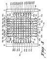
- Slicing apparatus 20 for particular use in slicing potatoes into strips for use in making "french fries” or similar product. It is to be understood that slicing apparatus 20 has applicability to slicing other kinds of vegetables into strips.
- Slicing apparatus 20 includes a plurality of blades arranged in a grid that receive potatoes from what is commonly referred to as a "gun” (not shown). Potatoes are launched one at a time with force against the slicing apparatus.
- the potatoes are entrained in a liquid such as water and moved by a large pump along a predetermined substantially straight path 21 (FIGS. 3, 4) toward slicing apparatus 20 entering at upstream end 28 and exiting at downstream end 29.
- Slicing apparatus 20 comprises a central tube 25 having an inside diameter slightly larger than the cross dimension of the potatoes being processed by apparatus 20.
- tube 25 had an inside diameter of 90 mm.
- Tube 25 has a cylindrical axis 26 that is collinear with predetermined path 21 of the potatoes.
- Tube 25 is attached to a base 27 having a central opening.
- tube 25 has eight sets of longitudinally extending slits 30a-d to 37a-d parallel to axis 26. Each slit on one side is laterally aligned with a slit on the opposite side.
- slit 30a on one side of tube 25 is aligned with slit 34a on the other side of the tube, and slit 31a on one side of tube 25 is aligned with a slit 35a on its other side.
- slits 33d and 37d on opposite sides are aligned and slits 36b and 32b on opposite sides are aligned.
- a blade extends through aligned pairs of slits as will be described.
- slicing apparatus 20 further comprises four mounting posts 40-43, which are located equiangularly about tube 25 and preferably are welded thereto.
- posts 40 and 42 are identical and posts 41 and 43 are identical.
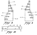
- Each mounting post has opposed, stepped sides for mounting the blades in a staggered arrangement as will be described.
- the four mounting posts have eight sets of surfaces 50a-d to 57a-d respectively adjacent to slits 30a-d to 37a-d. In each surface is a threaded hole 44.
- Slicing apparatus 20 further comprises four sets of blades 60a-d to 63a-d.
- Blades 60a-d extend through slits 30a-d and 34a-d, respectively, and are mounted on surfaces 50a-d and 54a-d, respectively.
- Blades 61a-d extend through slits 31a-d and 35a-d, respectively, and are attached to surfaces 51a-d and 55a-d, respectively.
- Blades 62a-d extend through slits 32a-d and 36a-d, respectively, and are attached to surfaces 52a-d and 56a-d, respectively.
- Blades 63a-d extend through slits 33a-d and 37a-d, respectively, and are attached to surfaces 53a-d and 57a-d, respectively.
- Screws 65 attach the blades into holes 44.
- Blades 60a-d and 61a-d lie in planes parallel to each other and parallel to axis 26.
- Blades 62a-d and 63a-d lie in planes parallel to each other and parallel to axis 26.
- the planes of blades 62a-d and 63a-d are perpendicular to the planes of blades 60a-d and 61a-d.
- Each blade is at an acute angle with respect to axis 26. In an actual embodiment, that angle was 60° (30° to a plane perpendicular to axis 26).
- all of blades 60a-d are parallel to each other and are at an angle of +60° with respect to axis 26.
- All of blades 61a-d are parallel and are at an angle of -60° to axis 26.
- all four blades 62a-d are parallel and are at an angle of +60° to axis 26 and blades 63a-d are at an angle of -60° to axis 26.
- the angle of the blades is determined by the relationship of the slits and the location of the holes on the posts. For example, referring to FIG. 7, slit 30a is closer to upstream end 28 and slit 34a is closer to downstream end 29.
- each blade includes one or more slots 66 at various locations and depths to accommodate its intersection with other blades.
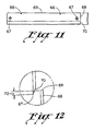
- Each blade also has mounting holes 67 through which screws 65 pass into the surfaces of the mounting posts.
- Each blade includes a trailing portion 68 terminating in a trailing edge 69, and a leading portion 70 terminating into a leading edge 71 which is sharpened.
- phantom lines 75 and 76 divide the blade array into four quadrants I-IV.
- quadrant I all of blades 61a-d and 62a-d are angled in the same direction, that is, toward downstream end 29.
- quadrant II all of blades 60a-d and 62a-d are angled in the same direction, that is, toward upstream end 28.
- quadrant III all of blades 60a-d and 63a-d are angled in the same direction, that is, toward downstream end 29.
- quadrant IV all of blades 61a-d and 63a-d are angled in the same direction, that is, toward upstream end 28.
- Posts 41 and 43 depicted in FIG. 9 and posts 40 and 42 depicted in FIG. 8 are slightly different. They all have the same number of staggered steps. However, the surfaces and the holes in posts 41 and 43 are slightly offset from the surfaces and the holes in posts 40 and 42. As a result, blade 63d is slightly downstream of blade 61d, for example.
- All of the blades are symmetrical about axis 26, so that the forces acting on a potato passing therethrough are balanced and, thereby to minimize the tendency of the blades to move the potato away from such axis.
- each pair of adjacent blades is arranged such that leading portion 70 overlaps trailing portion 68.
- the amount 72 of overlap was 4mm.
- this overlap exists in each pair of adjacent blades that extends in the same direction.
- blades 63a and b overlap, blades 63b and 63c overlap and blades 63c and 63d overlap.
- the same may be said of adjacent pairs of blades in the other three sets. It would not apply to blades angled in opposite directions.
- the term "overlap" would not be descriptive of adjacent blades 63a and 62d, nor blades 61a and 60d.
- Overlap tends to reduce what is called "shatter.”
- the blade does not cut the vegetable in the sense that it always is in contact with the forward edge of the cut. Rather, after initial contact of the cutting edge with the vegetable, the product is actually split or separated slightly ahead of the edge because of the stress in the vegetable due to the existence of the blade therein.
- the blades are thin, the vegetable being cut is deformed around the bevel of the blade and is thus distorted. The distortion causes stress in the cut potato transversely to the blade. Fracture occurs transversely to this direction and in the plane of the cut. These stress fractures tend to promote breakage of the vegetable as it moves through the blade.
- trailing portion 68 of one blade tends to constrain the portion of the potato P against the leading portion 70 of the adjacent blade.
- trailing portion 68 constrains the potato and prevents it from doing so.
- FIG. 14 An alternative embodiment is depicted in FIG. 14 where the amount of overlap is reduced, say to 2mm, but a rib 73 is added to trailing portion 68. Such rib increases the pressure on the portion of the potato at the cutting edge and increases its ability to constrain the potato.
- Tube 25 which restricts lateral movement of the water in which the potatoes are entrained. Any such lateral movement tends to divert the potato from its preferred orientation in which its longitudinal axis is aligned with cylinder axis 26. Tube 25 guides the potato along axis 26 by precluding lateral movement of both the water and the potato.
- the food slicing apparatus is designed to accommodate potatoes having a cross dimension of less than 90mm.
- Apparatus 20 has eight blades in one set of parallel planes and another set of eight blades in planes perpendicular to the first set.
- a tube of 70mm ID or cross dimension can be employed along with two sets of six blades each, in which event the potato strips would still have a cross dimension of 10mm.
Landscapes
- Life Sciences & Earth Sciences (AREA)
- Forests & Forestry (AREA)
- Engineering & Computer Science (AREA)
- Mechanical Engineering (AREA)
- Preparation Of Fruits And Vegetables (AREA)
- Control And Other Processes For Unpacking Of Materials (AREA)
- Paper (AREA)
- Apparatuses For Bulk Treatment Of Fruits And Vegetables And Apparatuses For Preparing Feeds (AREA)
- Food-Manufacturing Devices (AREA)
- Formation And Processing Of Food Products (AREA)
Claims (15)
- Ein Gerät zum Zerschneiden von Stücken oder Teilen pflanzlicher Nahrung, insbesondere Gemüse, in Streifen bzw. Schnitzel (zum Beispiel für Pommes Frites); die Nahrungsstücke bewegen sich dabei durch das Gerät längs einer vorbestimmten Bewegungsbahn (21), das Gerät weist ein Rohr (25) mit einem den hindurchgehenden Gemüsestücken entsprechenden Durchmesser auf, wobei die Längsachse (26) im wesentlichen der Bewegungsrichtung (21) entspricht, eine Vielzahl längsgestreckter erster Messer (60a-d) liegen in zueinander parallelen ersten Ebenen, und eine Vielzahl längsgestreckter zweiter Messer (62a-d) liegen in zueinander parallelen zweiten Ebenen im wesentlichen rechtwinkelig zu den ersten Ebenen, jedes der ersten und jedes der zweiten Messer (60a-d, 62a-d) hat einen vorderen Teil oder Bereich und einen rückwärtigen Bereich (70, 68) und jeder der vorderen Bereiche (70) endet in eine vordere geschärfte Schneidkante (71), dadurch gekennzeichnet, dass die erwähnten ersten Messer (60a-d) in einem ersten spitzen Winkel gegenüber der Bewegungsrichtung (21) vorgesehen sind, und die zweiten Messer (62a-d) sind in einem zweiten spitzen Winkel gegenüber der Bewegungsrichtung (21) vorgesehen, und dass die vorderen und die rückwärtigen Bereiche (70, 68) einander benachbarter erster Messer (60a-d) einander überlappen, und die vorderen und die hinteren Bereiche (70, 68) benachbarter zweiter Messer (62a-d) überlappen einander, und dass das Gerät ferner Stützmittel (Messerträger) (40-43) ausserhalb des Rohres aufweist, wobei sich die Messer (60a-d, 61a-d, 62a-d, 63a-d) durch das Rohr (25) hindurch erstrecken und abnehmbar an den Messerträgern angebracht sind.
- Ein Gerät gemäss Anspruch 1, weiter bestückt mit einer Vielzahl länglicher dritter Messer (61a-d) unter einem dritten spitzen Winkel gegenüber der Bewegungsrichtung, die dritten Messer (61a-d) liegen in dritten Ebenen im wesentlichen parallel mit den ersten Ebenen, wobei der dritte spitze Winkel verschieden ist von dem ersten spitzen Winkel, und eine Vielzahl längsgestreckter dritter Messer (63a-d) ist vorgesehen unter einem vierten spitzen Winkel gegenüber der Bewegungsrichtung, die vierten Messer (63a-d) liegen in vierten Ebenen im wesentlichen parallel zu den zweiten Ebenen, und der vierte spitze Winkel ist verschieden von dem zweiten spitzen Winkel.
- Gerät nach Anspruch 2, wobei der erste Winkel im wesentlichen gleich ist dem dritten Winkel, jedoch von entgegengesetzter Polarität, und der zweite Winkel ist im wesentlichen gleich dem vierten Winkel, jedoch von entgegengesetzter Polarität.
- Gerät nach Anspruch 2 oder 3, wobei jedes der dritten und der vierten Messer (61a-d, 63a-d) vordere und rückwärtige Bereiche (70, 68) hat und jeder der vorderen Bereiche (70) in einer geschärften vorderen Schneidkante (71) endet, die vorderen und hinteren Bereiche (70, 80) wenigstens eines Paares von einander benachbarten ersten Klingen (61a-d) überlappen einander, und die vorderen und rückwärtigen Bereiche (70, 68) und wenigstens eines Teiles einander benachbarter vierter Klingen (63a-d) überlappen einander.
- Das Gerät nach einem der Ansprüche 2 bis 4, dadurch gekennzeichnet, dass jeweils vier erste Messer (60a-d) und vier zweite Messer (62a-d) und vier dritte Messer (61a-d) und jeweils vier vierte Messer (63a-d) vorgesehen sind.
- Ein Gerät nach einem der vorhergehenden Ansprüche, wobei das Ausmass der Überlappung im Bereich von 4 mm liegt.
- Ein Gerät nach einem der vorhergehenden Ansprüche, wobei die absoluten Werte der besagten Winkel ungefähr 60° beträgt.
- Ein Gerät gemäss irgendeinem der vorausgehenden Ansprüche, wobei der Abstand zwischen den Messern (60a-d, 61a-d, 62a-d, 63a-d) innerhalb eines jeden Messersatzes im wesentlichen gleich ist.
- Ein Gerät gemäss Anspruch 8, wobei der Abstand zwischen den Messern (60a-d, 61a-d, 62a-d, 63a-d) ungefähr 10 mm beträgt.
- Ein Gerät nach einem der vorausgehenden Ansprüche, wobei das Rohr (25) Schlitze hat, durch welche sich die Messer (60a-d, 61a-d, 62a-d, 63a-d) erstrecken.
- Das Gerät nach einem der vorausgehenden Ansprüche, wobei die Stützteile (40-43) an dem Rohr festgemacht sind.
- Das Gerät nach Anspruch 11, wobei die Messer (60a-d, 61a-d, 62a-d, 63a-d) mittels Schrauben (65) an den Messerhaltern (40-43) festgemacht sind.
- Ein Gerät nach Anspruch 11 oder 12, wobei die Stützmittel (40-43) vier Arbeitsstellen oder -posten (40-43) einschliessen, die mit gleichem Winkelabstand um das Rohr (25) herum angeordnet sind, jeder Posten hat gestufte Seiten, die Messer (60a-d, 61a-d, 62a-d, 63a-d) sind abnehmbar an den Seiten festgemacht.
- Das Gerät nach einem der Ansprüche 11 bis 13, ferner umfassend eine an dem Rohr (25) angebrachte Basis (27).
- Das Gerät nach irgendeinem der vorausgehenden Ansprüche, wobei die rückwärtigen Bereiche (68) jedes Messers (60a-d, 61a-d, 62a-d, 63a-d) ferner eine Rippe (73) aufweist, die hervorsteht über die Oberfläche und gegen den überlappenden vorderen Bereich (70) eines benachbarten Messers (60a-d, 61a-d, 62a-d, 63a-d) gerichtet ist.
Applications Claiming Priority (2)
| Application Number | Priority Date | Filing Date | Title |
|---|---|---|---|
| AU5313/92 | 1992-10-16 | ||
| AUPL531392 | 1992-10-16 |
Publications (2)
| Publication Number | Publication Date |
|---|---|
| EP0593309A1 EP0593309A1 (de) | 1994-04-20 |
| EP0593309B1 true EP0593309B1 (de) | 1998-02-25 |
Family
ID=3776479
Family Applications (1)
| Application Number | Title | Priority Date | Filing Date |
|---|---|---|---|
| EP93308257A Expired - Lifetime EP0593309B1 (de) | 1992-10-16 | 1993-10-15 | Einrichtung zum Schneiden von Lebensmitteln |
Country Status (8)
| Country | Link |
|---|---|
| US (1) | US5655428A (de) |
| EP (1) | EP0593309B1 (de) |
| AT (1) | ATE163389T1 (de) |
| AU (1) | AU675244B2 (de) |
| BR (1) | BR9304243A (de) |
| CA (1) | CA2108506A1 (de) |
| DE (1) | DE69317087T2 (de) |
| NZ (1) | NZ248967A (de) |
Families Citing this family (22)
| Publication number | Priority date | Publication date | Assignee | Title |
|---|---|---|---|---|
| USD423318S (en) * | 1999-03-03 | 2000-04-25 | Lacy Brian W | Media package opener |
| NL1013937C2 (nl) | 1999-12-23 | 2001-06-26 | Aviko Bv | Inrichting voor het snijden van aardappelen of andere groenten in schijfjes of staafjes. |
| US6725765B1 (en) | 2003-01-10 | 2004-04-27 | George A. Mendenhall | Cutter blade assembly for cutting vegetable products |
| US6959636B2 (en) * | 2003-04-02 | 2005-11-01 | Prime Slice, Llc | Produce slicer |
| US7739949B2 (en) * | 2006-07-14 | 2010-06-22 | Neil Justesen | Method and device for cutting and coring materials in a hydrocutting apparatus |
| WO2008052492A1 (de) * | 2006-10-29 | 2008-05-08 | Ralf Detlef Barthel | Schneidelementen-anordnung in einer vorrichtung zum zerkleinern von früchten |
| NL1038863C2 (nl) * | 2011-06-07 | 2012-12-10 | Tummers Beheer B V | Een deelbaar klemsnijblok voor het snijden van knolvormige produkten. |
| US9943978B2 (en) | 2011-10-11 | 2018-04-17 | J.R. Simplot Company | System for cutting spiral shaped pieces |
| US9089987B2 (en) * | 2011-10-11 | 2015-07-28 | J.R. Simplot Company | Rotary knife fixture for cutting spiral, textured potato pieces |
| FR3001909B1 (fr) * | 2013-02-11 | 2015-02-27 | Mc Cain Foods Ltd | Bloc de decoupe de produits alimentaires en fragments en "s" |
| WO2015039061A1 (en) * | 2013-09-16 | 2015-03-19 | Vanmark Equipment, Llc | Rotating cutting blade assembly |
| US10160132B2 (en) * | 2015-09-11 | 2018-12-25 | J.R. Simplot Company | Flow-propelled rotary knife |
| USD766542S1 (en) | 2015-10-29 | 2016-09-20 | J.R. Simplot Company | Twisted potato piece |
| CN106944964B (zh) * | 2017-05-12 | 2018-08-07 | 温岭市智营电子科技有限公司 | 一种改进型多功能螺丝刀及其使用方法 |
| USD894682S1 (en) * | 2018-11-12 | 2020-09-01 | Lamb Weston, Inc. | Cutter for food products |
| USD895358S1 (en) * | 2018-11-12 | 2020-09-08 | Lamb Weston, Inc. | Cutter for food products |
| USD895359S1 (en) * | 2018-11-12 | 2020-09-08 | Lamb Weston, Inc. | Cutter for food products |
| USD894681S1 (en) * | 2018-11-12 | 2020-09-01 | Lamb Weston, Inc. | Cutter for food products |
| USD896033S1 (en) * | 2019-06-13 | 2020-09-15 | Lamb Weston, Inc. | Cutter for food products |
| USD896031S1 (en) * | 2019-06-13 | 2020-09-15 | Lamb Weston, Inc. | Cutter for food products |
| USD896032S1 (en) * | 2019-06-13 | 2020-09-15 | Lamb Weston, Inc. | Cutter for food products |
| CA3249108A1 (en) * | 2022-04-29 | 2023-11-02 | Stumabo International N.V. | CUTTING HEAD AND KNIFE SET FOR CUTTING FOOD PRODUCTS INTO STRIPS, AND SET |
Family Cites Families (17)
| Publication number | Priority date | Publication date | Assignee | Title |
|---|---|---|---|---|
| US1910380A (en) * | 1931-04-25 | 1933-05-23 | Daum Charles | Food slicer |
| US2150735A (en) * | 1937-08-03 | 1939-03-14 | Libby Mcneill & Libby | Machine for longitudinally and transversely slicing pickles and the like |
| US2487431A (en) * | 1948-07-23 | 1949-11-08 | John B Floyd | Knife head for apple slicing machinery |
| US3109468A (en) * | 1961-02-24 | 1963-11-05 | Lamb Weston Inc | Vegetable slicing apparatus |
| US4059037A (en) * | 1976-04-26 | 1977-11-22 | Fasline Food Equipment Co. | Slicing device |
| US4300429A (en) * | 1977-09-23 | 1981-11-17 | Amfac Foods, Inc. | Cutter element |
| US4275086A (en) * | 1977-09-23 | 1981-06-23 | Amfac Foods, Inc. | Method of preparing potato segments |
| GB2130473B (en) * | 1979-10-02 | 1984-11-07 | Nat Res Dev | Comminuting apparatus |
| US4372184A (en) * | 1981-02-25 | 1983-02-08 | J. R. Simplot Company | Cutting assembly |
| US5009141A (en) * | 1985-09-23 | 1991-04-23 | Lamb-Weston, Inc. | Blade assembly for slicing food products |
| NL8700507A (nl) * | 1987-03-03 | 1988-10-03 | Tech Handelsbureau A Nieuwenhu | Snijkop voor het tot staafjes of frites versnijden van aardappelen. |
| US4766793A (en) * | 1987-06-08 | 1988-08-30 | Urschel Laboratories, Inc. | Knife assembly for a water gun |
| US5046388A (en) * | 1987-06-08 | 1991-09-10 | Mendenhall George A | Decorative form hydraulic cutting blade assembly |
| ATE72163T1 (de) * | 1988-02-02 | 1992-02-15 | George A Mendenhall | Verfahren und vorrichtung zum hydraulischen schneiden von lebensmitteln. |
| US5058478A (en) * | 1988-04-13 | 1991-10-22 | Mendenhall George A | Cutter blade assembly for hydraulic food cutting apparatus |
| US5101718A (en) * | 1990-04-27 | 1992-04-07 | Thomas Lin | Cutting device |
| US5125308A (en) * | 1991-03-11 | 1992-06-30 | Mendenhall George A | Soft core cutting blade assembly for hydraulic food cutting apparatus |
-
1993
- 1993-10-15 EP EP93308257A patent/EP0593309B1/de not_active Expired - Lifetime
- 1993-10-15 AT AT93308257T patent/ATE163389T1/de not_active IP Right Cessation
- 1993-10-15 NZ NZ248967A patent/NZ248967A/en unknown
- 1993-10-15 AU AU49033/93A patent/AU675244B2/en not_active Ceased
- 1993-10-15 BR BR9304243A patent/BR9304243A/pt not_active IP Right Cessation
- 1993-10-15 CA CA002108506A patent/CA2108506A1/en not_active Abandoned
- 1993-10-15 DE DE69317087T patent/DE69317087T2/de not_active Expired - Fee Related
-
1995
- 1995-08-02 US US08/510,330 patent/US5655428A/en not_active Expired - Fee Related
Also Published As
| Publication number | Publication date |
|---|---|
| US5655428A (en) | 1997-08-12 |
| BR9304243A (pt) | 1994-04-19 |
| AU675244B2 (en) | 1997-01-30 |
| AU4903393A (en) | 1994-04-28 |
| CA2108506A1 (en) | 1994-04-17 |
| NZ248967A (en) | 1996-07-26 |
| DE69317087T2 (de) | 1998-08-06 |
| ATE163389T1 (de) | 1998-03-15 |
| EP0593309A1 (de) | 1994-04-20 |
| DE69317087D1 (de) | 1998-04-02 |
Similar Documents
| Publication | Publication Date | Title |
|---|---|---|
| US5655428A (en) | Food slicing apparatus | |
| US5009141A (en) | Blade assembly for slicing food products | |
| CN104582914B (zh) | 用于切割食品的方法和装备 | |
| US7073260B2 (en) | Knife assembly | |
| US6962040B2 (en) | Sickle knife with double overlapping out of phase sickles | |
| EP0295004B1 (de) | Schneidmesseraufbau für Produkte, die durch Druckwasser transportiert werden | |
| US4423652A (en) | Potato centering device | |
| US5992284A (en) | Knife and cutting wheel for a food product slicing apparatus | |
| EP1377415B1 (de) | Laufrad für rotierenden scheibenschneidmaschine | |
| EP3280572B1 (de) | Schneidscheiben und messeranordnungen davon zum schneiden von produkten | |
| US20080166189A1 (en) | Double-sided wear insert for a chipper | |
| EP0377075A3 (de) | Gemüseschneidvorrichtung | |
| BR102014016499A2 (pt) | cortador de orifícios | |
| US4346744A (en) | Wood waferizing apparatus | |
| GB2113137A (en) | Knives | |
| JPH0398531A (ja) | 魚肉の切身をつくる装置 | |
| EP1289717B1 (de) | Schneidmesser zum schneiden von lebensmitteln | |
| CA2386699A1 (en) | Comminuting unit of a comminuting machine for comminuting material, especially knife block for a wood slicer | |
| KR200484761Y1 (ko) | 인쇄용지 컷팅장치 | |
| CA2514442A1 (en) | Chipper knife | |
| DE1654867B2 (de) | Vorrichtung zum nobben von fischen | |
| FI922817A0 (fi) | Foerfarande och anordning foer saogning eller skaerning av styvt saogningsmaterial. | |
| CA1327934C (en) | Lattice blade | |
| AU772933B2 (en) | Knife for a food product slicing apparatus | |
| KR20230160929A (ko) | 식품 절단기 및 식품 절단 방법 |
Legal Events
| Date | Code | Title | Description |
|---|---|---|---|
| PUAI | Public reference made under article 153(3) epc to a published international application that has entered the european phase |
Free format text: ORIGINAL CODE: 0009012 |
|
| AK | Designated contracting states |
Kind code of ref document: A1 Designated state(s): AT BE CH DE DK ES FR GB GR IE IT LI LU MC NL PT SE |
|
| 17P | Request for examination filed |
Effective date: 19941004 |
|
| 17Q | First examination report despatched |
Effective date: 19950726 |
|
| GRAG | Despatch of communication of intention to grant |
Free format text: ORIGINAL CODE: EPIDOS AGRA |
|
| GRAG | Despatch of communication of intention to grant |
Free format text: ORIGINAL CODE: EPIDOS AGRA |
|
| GRAH | Despatch of communication of intention to grant a patent |
Free format text: ORIGINAL CODE: EPIDOS IGRA |
|
| GRAH | Despatch of communication of intention to grant a patent |
Free format text: ORIGINAL CODE: EPIDOS IGRA |
|
| GRAA | (expected) grant |
Free format text: ORIGINAL CODE: 0009210 |
|
| AK | Designated contracting states |
Kind code of ref document: B1 Designated state(s): AT BE CH DE DK ES FR GB GR IE IT LI LU MC NL PT SE |
|
| PG25 | Lapsed in a contracting state [announced via postgrant information from national office to epo] |
Ref country code: LI Free format text: LAPSE BECAUSE OF FAILURE TO SUBMIT A TRANSLATION OF THE DESCRIPTION OR TO PAY THE FEE WITHIN THE PRESCRIBED TIME-LIMIT Effective date: 19980225 Ref country code: IT Free format text: LAPSE BECAUSE OF FAILURE TO SUBMIT A TRANSLATION OF THE DESCRIPTION OR TO PAY THE FEE WITHIN THE PRE;WARNING: LAPSES OF ITALIAN PATENTS WITH EFFECTIVE DATE BEFORE 2007 MAY HAVE OCCURRED AT ANY TIME BEFORE 2007. THE CORRECT EFFECTIVE DATE MAY BE DIFFERENT FROM THE ONE RECORDED.SCRIBED TIME-LIMIT Effective date: 19980225 Ref country code: GR Free format text: LAPSE BECAUSE OF FAILURE TO SUBMIT A TRANSLATION OF THE DESCRIPTION OR TO PAY THE FEE WITHIN THE PRESCRIBED TIME-LIMIT Effective date: 19980225 Ref country code: ES Free format text: THE PATENT HAS BEEN ANNULLED BY A DECISION OF A NATIONAL AUTHORITY Effective date: 19980225 Ref country code: CH Free format text: LAPSE BECAUSE OF FAILURE TO SUBMIT A TRANSLATION OF THE DESCRIPTION OR TO PAY THE FEE WITHIN THE PRESCRIBED TIME-LIMIT Effective date: 19980225 Ref country code: AT Free format text: LAPSE BECAUSE OF FAILURE TO SUBMIT A TRANSLATION OF THE DESCRIPTION OR TO PAY THE FEE WITHIN THE PRESCRIBED TIME-LIMIT Effective date: 19980225 |
|
| REF | Corresponds to: |
Ref document number: 163389 Country of ref document: AT Date of ref document: 19980315 Kind code of ref document: T |
|
| REG | Reference to a national code |
Ref country code: CH Ref legal event code: EP |
|
| REF | Corresponds to: |
Ref document number: 69317087 Country of ref document: DE Date of ref document: 19980402 |
|
| PG25 | Lapsed in a contracting state [announced via postgrant information from national office to epo] |
Ref country code: SE Free format text: LAPSE BECAUSE OF FAILURE TO SUBMIT A TRANSLATION OF THE DESCRIPTION OR TO PAY THE FEE WITHIN THE PRESCRIBED TIME-LIMIT Effective date: 19980525 Ref country code: PT Free format text: LAPSE BECAUSE OF FAILURE TO SUBMIT A TRANSLATION OF THE DESCRIPTION OR TO PAY THE FEE WITHIN THE PRESCRIBED TIME-LIMIT Effective date: 19980525 Ref country code: DK Free format text: LAPSE BECAUSE OF FAILURE TO SUBMIT A TRANSLATION OF THE DESCRIPTION OR TO PAY THE FEE WITHIN THE PRESCRIBED TIME-LIMIT Effective date: 19980525 |
|
| ET | Fr: translation filed | ||
| REG | Reference to a national code |
Ref country code: IE Ref legal event code: FG4D Free format text: 78969 |
|
| REG | Reference to a national code |
Ref country code: CH Ref legal event code: PL |
|
| PG25 | Lapsed in a contracting state [announced via postgrant information from national office to epo] |
Ref country code: LU Free format text: LAPSE BECAUSE OF NON-PAYMENT OF DUE FEES Effective date: 19981015 Ref country code: IE Free format text: LAPSE BECAUSE OF NON-PAYMENT OF DUE FEES Effective date: 19981015 |
|
| PLBE | No opposition filed within time limit |
Free format text: ORIGINAL CODE: 0009261 |
|
| 26N | No opposition filed | ||
| PG25 | Lapsed in a contracting state [announced via postgrant information from national office to epo] |
Ref country code: MC Free format text: LAPSE BECAUSE OF NON-PAYMENT OF DUE FEES Effective date: 19990430 |
|
| REG | Reference to a national code |
Ref country code: GB Ref legal event code: IF02 |
|
| PGFP | Annual fee paid to national office [announced via postgrant information from national office to epo] |
Ref country code: GB Payment date: 20030926 Year of fee payment: 11 |
|
| PGFP | Annual fee paid to national office [announced via postgrant information from national office to epo] |
Ref country code: BE Payment date: 20031015 Year of fee payment: 11 |
|
| PGFP | Annual fee paid to national office [announced via postgrant information from national office to epo] |
Ref country code: FR Payment date: 20031030 Year of fee payment: 11 |
|
| PGFP | Annual fee paid to national office [announced via postgrant information from national office to epo] |
Ref country code: NL Payment date: 20031031 Year of fee payment: 11 |
|
| PGFP | Annual fee paid to national office [announced via postgrant information from national office to epo] |
Ref country code: DE Payment date: 20031121 Year of fee payment: 11 |
|
| PG25 | Lapsed in a contracting state [announced via postgrant information from national office to epo] |
Ref country code: GB Free format text: LAPSE BECAUSE OF NON-PAYMENT OF DUE FEES Effective date: 20041015 |
|
| PG25 | Lapsed in a contracting state [announced via postgrant information from national office to epo] |
Ref country code: BE Free format text: LAPSE BECAUSE OF NON-PAYMENT OF DUE FEES Effective date: 20041031 |
|
| BERE | Be: lapsed |
Owner name: *MCCAIN FOODS (AUST) PTY. LTD Effective date: 20041031 |
|
| PG25 | Lapsed in a contracting state [announced via postgrant information from national office to epo] |
Ref country code: NL Free format text: LAPSE BECAUSE OF NON-PAYMENT OF DUE FEES Effective date: 20050501 |
|
| PG25 | Lapsed in a contracting state [announced via postgrant information from national office to epo] |
Ref country code: DE Free format text: LAPSE BECAUSE OF NON-PAYMENT OF DUE FEES Effective date: 20050503 |
|
| GBPC | Gb: european patent ceased through non-payment of renewal fee |
Effective date: 20041015 |
|
| PG25 | Lapsed in a contracting state [announced via postgrant information from national office to epo] |
Ref country code: FR Free format text: LAPSE BECAUSE OF NON-PAYMENT OF DUE FEES Effective date: 20050630 |
|
| NLV4 | Nl: lapsed or anulled due to non-payment of the annual fee |
Effective date: 20050501 |
|
| REG | Reference to a national code |
Ref country code: FR Ref legal event code: ST |
|
| BERE | Be: lapsed |
Owner name: *MCCAIN FOODS (AUST) PTY. LTD Effective date: 20041031 |