EP0593632B1 - Ventilateur radial - Google Patents
Ventilateur radial Download PDFInfo
- Publication number
- EP0593632B1 EP0593632B1 EP92915323A EP92915323A EP0593632B1 EP 0593632 B1 EP0593632 B1 EP 0593632B1 EP 92915323 A EP92915323 A EP 92915323A EP 92915323 A EP92915323 A EP 92915323A EP 0593632 B1 EP0593632 B1 EP 0593632B1
- Authority
- EP
- European Patent Office
- Prior art keywords
- fan
- partition wall
- air
- axial
- radial
- Prior art date
- Legal status (The legal status is an assumption and is not a legal conclusion. Google has not performed a legal analysis and makes no representation as to the accuracy of the status listed.)
- Expired - Lifetime
Links
Images


Classifications
-
- F—MECHANICAL ENGINEERING; LIGHTING; HEATING; WEAPONS; BLASTING
- F04—POSITIVE - DISPLACEMENT MACHINES FOR LIQUIDS; PUMPS FOR LIQUIDS OR ELASTIC FLUIDS
- F04D—NON-POSITIVE-DISPLACEMENT PUMPS
- F04D27/00—Control, e.g. regulation, of pumps, pumping installations or pumping systems specially adapted for elastic fluids
Definitions
- the present invention relates to a radial fan, especially a fan which is used in cars for suction of fresh air and possibly at the same time recirculation and mixing of air being present in the car. It can also be used for the choice of or mixing of gas streams in other connections, for example in the ventilation system in buildings.
- the input openings of fresh air can be of different constructions and they can be located at different places in the car but it is at present usual that they consist of a bar protected opening in the plate in front of the front wind screen.
- This opening can at some older models be closed by means of a shutter which is operated from the inside of the car, the shutter in the open position acting as an air scoop for the air. It is however usual that the air intake can not be closed in this way and the air channels are usually closed further in the car by means of valves or the like.
- fans and valves for this purpose are already known. They may be simple or very complicated but a common feature with all these is that the air streams are controlled by means of different valve arrangements.
- the fan arrangement can also be moveable to bring about certain streaming effects. See for instance the Japanese patent application 58-168906.
- a radial fan for for example cars comprising radially arranged fan plates having an axial extension for axial suction and radial blowing of a medium such as air which radial fan is characterized by an on the shaft arranged axially moveable and adaptable radially directed partition wall which extends outwardly at least to the plates and suction openings at either side of the partition wall.
- the partition wall is slidably mounted on a shaft in the shape of an axially slotted pipe and that it via a projection through the slot is connected to a threaded shaft within the pipe, a wire or spring for axial movement of the partition wall.
- the threaded shaft is rotatable by means of a position motor.
- the spokes which at one of the axial ends carry the fan plates have a shape as an axial fan.
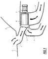
- Fig. 1 shows a fresh air channel 1 arranged at the end of of the bonnet 2 in front of the wind screen 3.
- a channel 4 for compartment air which is intended to be circulated.
- a valve 5 is arranged, which can control the mutual amount ratios between the air streams in the channels 1 and 4.
- a radial fan 6 which is driven by an electric motor 7. This radial fan blows the mixed air coming from the channels 1 and 4 into the compartment through the channel 9.
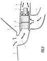
- Fig. 2 shows the same conventional ventilation arrangement as the one according to Fig. 1. The difference is that the valve 5 in Fig. 2 has been opened more that what is the case in Fig. 1 with relation to the circulation air channel 4. This can in spite of the influence from the radial fan 6 result in that the outside air which comes in through the channel 1 and is intended to stream into the compartment via the channels 8 and 9 partly takes a way into the channel 4 against the intended air stream. If this occurs or not depends on the speed of the car and how much the valve 5 has been opened and the speed of the fan. In a case like this one, no circulation of the compartment air will of course occur, neither will any heating of it be brought about.
- Fig. 3 shows a fresh air arrangement comprising the radial fan according to the present invention.
- the outside air is blown through the channel 1 directly against the radial fan 6 from the front side whereas the compartment air is sucked in against the radial fan from the other axial side through the channel 10.
- the combined air streams are blown thereafter via the channel 11 out into the compartment.
- the necessary and substantial partition wall 12 according to the invention for this arrangement is shown schematically on the radial fan 6.
- FIG. 4 A preferred embodiment of the invention is shown in Fig. 4.
- the fan shown is driven by an electric motor 7 in a conventional way via a shaft 13 which by means of a frame or spokes 14 in a known way carry the fan plates 15. These are extending axially and extend also radially outwards.
- a cylindrical cavity exists in which the partition wall 12 has been arranged.
- the partition wall is slidably mounted on a pipe shaped shaft 16 which is provided with an axial slot. Through this slot a projection 17 extend from the partition wall 12 which protrusion 17 engages a threaded shaft 18.
- This threaded shaft 18 is mounted in the car body and can be rotated by means of a position motor 19.
- the partition wall 12 can consequently be displaced to a desired axial position as the projection 17 is provided with inner threads which engage the threads on the shaft 18.
- an arrangement with wires and springs can be used. Stops 20 are arranged on the pipe shaped shaft 16 for limiting the displacement of the partition wall 12.
- the displacement of the wall 12 can be carried out by pushing a button in the drivers compartment or it can be moved automatically in that desired temperature or mixing ratio is put in a computer which via sensors also is informed of the pressure e t c of the incoming air and thus automatically can place the wall 12 in a correct position.
- the displacement of the wall 12 can of course be carried out in another way than by the arrangement shown. It can be pulled or pushed or guided by guiding elements in the disc in the periphery of the partition wall or at some other place. It is also possible that the fan plates 15 extend longer radially which means that the partition wall must be slotted and that it then has to follow the rotation.
- these can be formed as propeller blades.
- the fan according to the invention can also completely close the medium stream from one axial end by displacing the partition wall completely to one or the other end. In such a way one can use what medium stream one wishes.
Landscapes
- Engineering & Computer Science (AREA)
- Mechanical Engineering (AREA)
- General Engineering & Computer Science (AREA)
- Structures Of Non-Positive Displacement Pumps (AREA)
- Ventilation (AREA)
- Air-Conditioning For Vehicles (AREA)
Abstract
Claims (4)
- Ventilateur radial par exemple pour véhicules automobiles, comprenant des pales de ventilateur (15) disposées radialement ayant une étendue axiale pour l'aspiration axiale et le refoulement radial d'un milieu tel que l'air par exemple, caractérisé par une paroi de séparation (12) déplaçable et réglable axialement, dirigée radialement, disposée sur l'arbre, laquelle paroi de séparation s'étend à l'extérieur des pales (15), des ouvertures d'aspiration étant prévues de chaque côté de la paroi de séparation (12).
- Ventilateur radial selon la revendication 1, caractérisé en ce que la paroi de séparation (12) est montée coulissante sur un arbre (16) sous forme d'un tube fendu axialement et en ce que, à travers la fente et par l'intermédiaire d'une protubérance (17) elle coopère avec un élément parmi un arbre fileté (18), des fils métalliques ou des ressorts situés dans le tube, pour le mouvement axial de la paroi de séparation (12).
- Ventilateur radial selon l'une quelconque des revendications 1 et 2, caractérisé en ce que l'arbre fileté (12) peut être entraîné en rotation au moyen d'un moteur de positionnement (19).
- Ventilateur radial selon l'une quelconque des revendications 1 à 3, caractérisé en ce que les plaques de ventilateur (15) sont portées au niveau d'une extrémité par des rayons (14) ayant la forme d'un ventilateur axial pour faciliter l'aspiration du milieu.
Applications Claiming Priority (3)
| Application Number | Priority Date | Filing Date | Title |
|---|---|---|---|
| SE9102098A SE468488B (sv) | 1991-07-05 | 1991-07-05 | Radialflaekt vilken har en paa sin axel anordnad axiellt roerlig och instaellbar radiellt riktad mellanvaegg |
| SE9102098 | 1991-07-05 | ||
| PCT/SE1992/000435 WO1993001414A1 (fr) | 1991-07-05 | 1992-06-17 | Ventilateur radial |
Publications (2)
| Publication Number | Publication Date |
|---|---|
| EP0593632A1 EP0593632A1 (fr) | 1994-04-27 |
| EP0593632B1 true EP0593632B1 (fr) | 1996-02-28 |
Family
ID=20383264
Family Applications (1)
| Application Number | Title | Priority Date | Filing Date |
|---|---|---|---|
| EP92915323A Expired - Lifetime EP0593632B1 (fr) | 1991-07-05 | 1992-06-17 | Ventilateur radial |
Country Status (7)
| Country | Link |
|---|---|
| US (1) | US5478275A (fr) |
| EP (1) | EP0593632B1 (fr) |
| JP (1) | JP3071463B2 (fr) |
| DE (1) | DE69208663T2 (fr) |
| ES (1) | ES2087544T3 (fr) |
| SE (1) | SE468488B (fr) |
| WO (1) | WO1993001414A1 (fr) |
Families Citing this family (13)
| Publication number | Priority date | Publication date | Assignee | Title |
|---|---|---|---|---|
| JPH09112268A (ja) * | 1995-10-19 | 1997-04-28 | Hitachi Constr Mach Co Ltd | エンジン冷却装置及び建設機械 |
| US6318358B1 (en) * | 2000-08-03 | 2001-11-20 | Jackel Incorporated | Furnace blower with double sided impeller |
| KR20020015938A (ko) * | 2000-08-23 | 2002-03-02 | 츠카모토 요시카타 | 컵부착 스포츠의류 |
| US6435828B1 (en) | 2001-01-12 | 2002-08-20 | Emerson Electric Co. | Split blade radial fan |
| US6514052B2 (en) | 2001-03-30 | 2003-02-04 | Emerson Electric Co. | Two sided radial fan for motor cooling |
| US20060093472A1 (en) * | 2004-11-02 | 2006-05-04 | Hsiu Yin Chen | Blower structure |
| US20070012495A1 (en) * | 2005-07-15 | 2007-01-18 | Shannon Robert V Jr | Internal combustion engine with air exhaust chimney for agricultural working vehicle |
| DE102006019328A1 (de) * | 2006-04-24 | 2007-10-25 | Behr Gmbh & Co. Kg | Ansauggebläseanordnung, insbesondere für eine Kraftfahrzeug-Klimaanlage |
| US20120037340A1 (en) * | 2010-08-10 | 2012-02-16 | Roy Komarnicki | Heat Exchange Fan Apparatus |
| JP6040435B2 (ja) * | 2012-10-19 | 2016-12-07 | サクラ精機株式会社 | 洗浄装置 |
| KR101416398B1 (ko) * | 2012-12-05 | 2014-08-06 | 현대자동차 주식회사 | 공조 시스템 |
| CN105485783B (zh) * | 2016-01-28 | 2018-07-03 | 海信(广东)空调有限公司 | 一种空调室内机 |
| DE102016005552A1 (de) * | 2016-05-09 | 2017-11-09 | Stiebel Eltron Gmbh & Co. Kg | Elektrischer Heizlüfter |
Family Cites Families (10)
| Publication number | Priority date | Publication date | Assignee | Title |
|---|---|---|---|---|
| DE324492C (de) * | 1914-02-07 | 1920-08-30 | Western Electric Co Ltd | Schaltungsanordnung fuer Fernsprechhaupt- und -nebenstellen mit doppelter Schluss-zeichengabe auf der Nebenstellenzentrale sowie auf dem Amte, bei der die UEber-wachungsrelais gleichzeitig zur Abgabe der Schlusszeichen bestimmt sind |
| US2537805A (en) * | 1945-12-17 | 1951-01-09 | Lau Blower Co | Blower |
| US2542121A (en) * | 1947-09-09 | 1951-02-20 | Eureka Williams Corp | Motor compressor unit |
| US2714485A (en) * | 1951-06-28 | 1955-08-02 | Adam D Goettl | Blower rotor construction |
| CH488940A (de) * | 1968-02-22 | 1970-04-15 | Karl Barth Mechanische Werksta | Ventilatorgehäuse, insbesondere für Heugebläse |
| CH541077A (de) * | 1971-06-26 | 1973-08-31 | Siemens Ag | Lüfteraggregat |
| US4244685A (en) * | 1978-09-21 | 1981-01-13 | Nortti-Tuote Oy | Means for automatic closing and opening of the air intake duct of an oil burner |
| US4779672A (en) * | 1985-11-19 | 1988-10-25 | Toyota Jidosha Kabushiki Kaisha | Air conditioner for vehicle having blower with auxiliary intake port |
| US4808068A (en) * | 1986-10-28 | 1989-02-28 | Intertherm Investments, Inc. | Blower unloading device |
| US5207557A (en) * | 1992-05-08 | 1993-05-04 | American Standard Inc. | Centrifugal fan having variable width blades |
-
1991
- 1991-07-05 SE SE9102098A patent/SE468488B/sv not_active IP Right Cessation
-
1992
- 1992-06-17 WO PCT/SE1992/000435 patent/WO1993001414A1/fr not_active Ceased
- 1992-06-17 EP EP92915323A patent/EP0593632B1/fr not_active Expired - Lifetime
- 1992-06-17 DE DE69208663T patent/DE69208663T2/de not_active Expired - Fee Related
- 1992-06-17 ES ES92915323T patent/ES2087544T3/es not_active Expired - Lifetime
- 1992-06-17 JP JP5501754A patent/JP3071463B2/ja not_active Expired - Fee Related
- 1992-06-17 US US08/170,331 patent/US5478275A/en not_active Expired - Lifetime
Also Published As
| Publication number | Publication date |
|---|---|
| ES2087544T3 (es) | 1996-07-16 |
| SE9102098D0 (sv) | 1991-07-05 |
| JPH06508900A (ja) | 1994-10-06 |
| JP3071463B2 (ja) | 2000-07-31 |
| DE69208663T2 (de) | 1996-10-02 |
| US5478275A (en) | 1995-12-26 |
| SE468488B (sv) | 1993-01-25 |
| EP0593632A1 (fr) | 1994-04-27 |
| WO1993001414A1 (fr) | 1993-01-21 |
| DE69208663D1 (de) | 1996-04-04 |
Similar Documents
| Publication | Publication Date | Title |
|---|---|---|
| US4802405A (en) | Automotive air-conditioner | |
| US5478275A (en) | Radial fan | |
| CN109572355A (zh) | 具有嵌套轴的旋转轴组件 | |
| CN109520019A (zh) | 空调室内机和具有其的空调器 | |
| EP3023273A2 (fr) | Appareil d'admission d'air d'un système hvac pour un véhicule | |
| EP2116787B1 (fr) | Unité de climatisation et système de climatisation la comportant | |
| CN116572711B (zh) | 一种空调出风口总成以及车辆 | |
| CN106247454B (zh) | 空调柜机和空调柜机的出风控制方法 | |
| US5730651A (en) | Independent directional-flow air ducts for low-profile window fan | |
| US20050048911A1 (en) | Self-adjusting system for a damper | |
| CN116811534B (zh) | 一种无风感空调出风口总成及车辆 | |
| JP6269432B2 (ja) | 車両用空調装置 | |
| US20120125316A1 (en) | Ventilation system for a range hood with exhaust and recirculation options | |
| CN117621774A (zh) | 一种出风口气流控制机构及车辆 | |
| JP6672124B2 (ja) | 車両用の空調装置 | |
| JPH11148493A (ja) | 送風機 | |
| KR20170119769A (ko) | 차량용 송풍장치 | |
| KR101715157B1 (ko) | 차량용 공조기의 송풍장치 | |
| JPH0645368Y2 (ja) | 自動車用空気調和装置 | |
| CN111174399B (zh) | 一种挡风机构及具有其的送风系统、空调及控制方法 | |
| JP4434072B2 (ja) | リンク装置および車両用空調装置 | |
| JPS638016A (ja) | 車両用空気調和装置 | |
| JPH0533364Y2 (fr) | ||
| JP2533263Y2 (ja) | 自動車用空調装置の配風ドア開閉レバー | |
| CN117190307A (zh) | 风道组件、柜式空调器及其控制方法 |
Legal Events
| Date | Code | Title | Description |
|---|---|---|---|
| PUAI | Public reference made under article 153(3) epc to a published international application that has entered the european phase |
Free format text: ORIGINAL CODE: 0009012 |
|
| 17P | Request for examination filed |
Effective date: 19940112 |
|
| AK | Designated contracting states |
Kind code of ref document: A1 Designated state(s): BE DE ES FR GB IT NL |
|
| 17Q | First examination report despatched |
Effective date: 19950428 |
|
| GRAH | Despatch of communication of intention to grant a patent |
Free format text: ORIGINAL CODE: EPIDOS IGRA |
|
| GRAA | (expected) grant |
Free format text: ORIGINAL CODE: 0009210 |
|
| AK | Designated contracting states |
Kind code of ref document: B1 Designated state(s): BE DE ES FR GB IT NL |
|
| REF | Corresponds to: |
Ref document number: 69208663 Country of ref document: DE Date of ref document: 19960404 |
|
| ITF | It: translation for a ep patent filed | ||
| REG | Reference to a national code |
Ref country code: ES Ref legal event code: BA2A Ref document number: 2087544 Country of ref document: ES Kind code of ref document: T3 |
|
| ET | Fr: translation filed | ||
| REG | Reference to a national code |
Ref country code: ES Ref legal event code: FG2A Ref document number: 2087544 Country of ref document: ES Kind code of ref document: T3 |
|
| PLBE | No opposition filed within time limit |
Free format text: ORIGINAL CODE: 0009261 |
|
| STAA | Information on the status of an ep patent application or granted ep patent |
Free format text: STATUS: NO OPPOSITION FILED WITHIN TIME LIMIT |
|
| 26N | No opposition filed | ||
| PGFP | Annual fee paid to national office [announced via postgrant information from national office to epo] |
Ref country code: NL Payment date: 20000629 Year of fee payment: 9 |
|
| PGFP | Annual fee paid to national office [announced via postgrant information from national office to epo] |
Ref country code: BE Payment date: 20000818 Year of fee payment: 9 |
|
| PGFP | Annual fee paid to national office [announced via postgrant information from national office to epo] |
Ref country code: ES Payment date: 20010614 Year of fee payment: 10 |
|
| PG25 | Lapsed in a contracting state [announced via postgrant information from national office to epo] |
Ref country code: BE Free format text: LAPSE BECAUSE OF NON-PAYMENT OF DUE FEES Effective date: 20010630 |
|
| BERE | Be: lapsed |
Owner name: VOLVO A.B. Effective date: 20010630 |
|
| PG25 | Lapsed in a contracting state [announced via postgrant information from national office to epo] |
Ref country code: NL Free format text: LAPSE BECAUSE OF NON-PAYMENT OF DUE FEES Effective date: 20020101 |
|
| REG | Reference to a national code |
Ref country code: GB Ref legal event code: IF02 |
|
| NLV4 | Nl: lapsed or anulled due to non-payment of the annual fee |
Effective date: 20020101 |
|
| PG25 | Lapsed in a contracting state [announced via postgrant information from national office to epo] |
Ref country code: ES Free format text: LAPSE BECAUSE OF NON-PAYMENT OF DUE FEES Effective date: 20020618 |
|
| REG | Reference to a national code |
Ref country code: ES Ref legal event code: FD2A Effective date: 20030711 |
|
| PGFP | Annual fee paid to national office [announced via postgrant information from national office to epo] |
Ref country code: FR Payment date: 20040602 Year of fee payment: 13 |
|
| PGFP | Annual fee paid to national office [announced via postgrant information from national office to epo] |
Ref country code: DE Payment date: 20040630 Year of fee payment: 13 |
|
| PGFP | Annual fee paid to national office [announced via postgrant information from national office to epo] |
Ref country code: GB Payment date: 20050506 Year of fee payment: 14 |
|
| PG25 | Lapsed in a contracting state [announced via postgrant information from national office to epo] |
Ref country code: IT Free format text: LAPSE BECAUSE OF NON-PAYMENT OF DUE FEES;WARNING: LAPSES OF ITALIAN PATENTS WITH EFFECTIVE DATE BEFORE 2007 MAY HAVE OCCURRED AT ANY TIME BEFORE 2007. THE CORRECT EFFECTIVE DATE MAY BE DIFFERENT FROM THE ONE RECORDED. Effective date: 20050617 |
|
| PG25 | Lapsed in a contracting state [announced via postgrant information from national office to epo] |
Ref country code: DE Free format text: LAPSE BECAUSE OF NON-PAYMENT OF DUE FEES Effective date: 20060103 |
|
| PG25 | Lapsed in a contracting state [announced via postgrant information from national office to epo] |
Ref country code: FR Free format text: LAPSE BECAUSE OF NON-PAYMENT OF DUE FEES Effective date: 20060228 |
|
| REG | Reference to a national code |
Ref country code: FR Ref legal event code: ST Effective date: 20060228 |
|
| PG25 | Lapsed in a contracting state [announced via postgrant information from national office to epo] |
Ref country code: GB Free format text: LAPSE BECAUSE OF NON-PAYMENT OF DUE FEES Effective date: 20060617 |
|
| GBPC | Gb: european patent ceased through non-payment of renewal fee |
Effective date: 20060617 |