EP0593685B1 - Teilbare hüllenanordnung - Google Patents
Teilbare hüllenanordnung Download PDFInfo
- Publication number
- EP0593685B1 EP0593685B1 EP92919181A EP92919181A EP0593685B1 EP 0593685 B1 EP0593685 B1 EP 0593685B1 EP 92919181 A EP92919181 A EP 92919181A EP 92919181 A EP92919181 A EP 92919181A EP 0593685 B1 EP0593685 B1 EP 0593685B1
- Authority
- EP
- European Patent Office
- Prior art keywords
- hemostatic valve
- sheath
- introducer sheath
- valve
- catheter
- Prior art date
- Legal status (The legal status is an assumption and is not a legal conclusion. Google has not performed a legal analysis and makes no representation as to the accuracy of the status listed.)
- Expired - Lifetime
Links
Images

Classifications
-
- A—HUMAN NECESSITIES
- A61—MEDICAL OR VETERINARY SCIENCE; HYGIENE
- A61M—DEVICES FOR INTRODUCING MEDIA INTO, OR ONTO, THE BODY; DEVICES FOR TRANSDUCING BODY MEDIA OR FOR TAKING MEDIA FROM THE BODY; DEVICES FOR PRODUCING OR ENDING SLEEP OR STUPOR
- A61M25/00—Catheters; Hollow probes
- A61M25/01—Introducing, guiding, advancing, emplacing or holding catheters
- A61M25/06—Body-piercing guide needles or the like
- A61M25/0662—Guide tubes
- A61M25/0668—Guide tubes splittable, tear apart
-
- A—HUMAN NECESSITIES
- A61—MEDICAL OR VETERINARY SCIENCE; HYGIENE
- A61M—DEVICES FOR INTRODUCING MEDIA INTO, OR ONTO, THE BODY; DEVICES FOR TRANSDUCING BODY MEDIA OR FOR TAKING MEDIA FROM THE BODY; DEVICES FOR PRODUCING OR ENDING SLEEP OR STUPOR
- A61M39/00—Tubes, tube connectors, tube couplings, valves, access sites or the like, specially adapted for medical use
- A61M39/02—Access sites
- A61M39/06—Haemostasis valves, i.e. gaskets sealing around a needle, catheter or the like, closing on removal thereof
- A61M2039/062—Haemostasis valves, i.e. gaskets sealing around a needle, catheter or the like, closing on removal thereof used with a catheter
-
- A—HUMAN NECESSITIES
- A61—MEDICAL OR VETERINARY SCIENCE; HYGIENE
- A61M—DEVICES FOR INTRODUCING MEDIA INTO, OR ONTO, THE BODY; DEVICES FOR TRANSDUCING BODY MEDIA OR FOR TAKING MEDIA FROM THE BODY; DEVICES FOR PRODUCING OR ENDING SLEEP OR STUPOR
- A61M39/00—Tubes, tube connectors, tube couplings, valves, access sites or the like, specially adapted for medical use
- A61M39/02—Access sites
- A61M39/06—Haemostasis valves, i.e. gaskets sealing around a needle, catheter or the like, closing on removal thereof
- A61M2039/0633—Haemostasis valves, i.e. gaskets sealing around a needle, catheter or the like, closing on removal thereof the seal being a passive seal made of a resilient material with or without an opening
-
- A—HUMAN NECESSITIES
- A61—MEDICAL OR VETERINARY SCIENCE; HYGIENE
- A61M—DEVICES FOR INTRODUCING MEDIA INTO, OR ONTO, THE BODY; DEVICES FOR TRANSDUCING BODY MEDIA OR FOR TAKING MEDIA FROM THE BODY; DEVICES FOR PRODUCING OR ENDING SLEEP OR STUPOR
- A61M39/00—Tubes, tube connectors, tube couplings, valves, access sites or the like, specially adapted for medical use
- A61M39/02—Access sites
- A61M39/06—Haemostasis valves, i.e. gaskets sealing around a needle, catheter or the like, closing on removal thereof
- A61M2039/0633—Haemostasis valves, i.e. gaskets sealing around a needle, catheter or the like, closing on removal thereof the seal being a passive seal made of a resilient material with or without an opening
- A61M2039/064—Slit-valve
-
- A—HUMAN NECESSITIES
- A61—MEDICAL OR VETERINARY SCIENCE; HYGIENE
- A61M—DEVICES FOR INTRODUCING MEDIA INTO, OR ONTO, THE BODY; DEVICES FOR TRANSDUCING BODY MEDIA OR FOR TAKING MEDIA FROM THE BODY; DEVICES FOR PRODUCING OR ENDING SLEEP OR STUPOR
- A61M39/00—Tubes, tube connectors, tube couplings, valves, access sites or the like, specially adapted for medical use
- A61M39/02—Access sites
- A61M39/06—Haemostasis valves, i.e. gaskets sealing around a needle, catheter or the like, closing on removal thereof
Definitions
- the invention relates to the field of pacemaker leads and catheters, and in particular to leads used in veins such as in connection with pacemaker procedures such as pacemaker lead insertion.
- a guidewire is introduced into the vessel through a hollow needle.
- the needle is withdrawn leaving the guidewire in the vessel.
- a TEFLON dilator and venous sheath assembly are then advanced in a rotary motion over the guidewire into the vessel.
- the TEFLON dilator and the guidewire are then removed leaving the flexible sheath in the vessel.
- various types of catheters or leads are inserted using the sheath as a conduit to avoid tearing or further trauma to the vessel wall.
- the pacemaker In the case where a pacemaker lead must be permanently inserted into the patient, the pacemaker is subcutaneously implanted in the patient and the lead, which extends from the pacemaker into the heart chamber, remains permanently disposed through the vessel wall and in the vessel lumen. A sheath is nevertheless used in order to guide insertion of the lead into vein lumen, but must be removed leaving the lead in place. However, the sheath cannot simply, in all cases, be slipped over the exterior end of the pacemaker lead which may be provided with a special termination for connection to the pacemaker.
- a splittable cannula is also taught by Kousai et al., “Medical Tool Introduction Cannula and Method of Manufacturing the Same," U.S. Patent 4,883,468 (1989).
- the sheath assembly in addition to the sheath assembly providing an open passage for the loss of blood, the sheath assembly also provides an open passage for the introduction of air into the vein.
- the inadvertent introduction of air into the blood system causes air embolism in the patient and its consequent negative effects.
- clotting may be formed in the lumen of the sheath if the sheath remains in for a prolonged time, and this may cause embolism to the lung and its consequent negative effects.
- the prior art splittable sheath has to be removed as soon as the lead is introduced into the vessel lumen, although it is very desirable to retain the sheath in place throughout operation because the lead can be manipulated much easier without interference from other existing lead or tissue friction and can be exchanged freely without repeated sheath insertion trauma.
- the prior art has also devised hemostatic valves which provide a seal around the catheter introduced through the sheath.
- One such sheath and hemostatic valve is manufactured and marketed by Cordis Corp. of Miami, Florida as the UNISTASIS valve in the Cordis catheter sheath introducer.
- Another example is manufactured by Bard of Billerica, Massachusetts as the 5F HEMAQUET introducer.
- a hemostatic valve combined with a splittable sheath is also illustrated in Schiff, "Introducer Assembly for Intra-Aortic Balloons and the Like Incorporating a Sliding, Blood-Tight Seal," U.S. Patent 4,473,067 (1984).
- DE 37 21 288 C1 describes only a sealing packing for a catheter introducer.
- the catheter introducer and the sealing packing are constituted of two separate components which are each formed of two separate halves.
- neither the introducer nor the sealing packing of DE 37 21 288 C1 are made of one piece but of two pieces.
- DE 38 34 600 C1 describes an apparatus for use for vascular implantation of a lead or catheter having a sheath and valve assembly.
- the sheath and valve assembly are constructed of two separate components which can not come apart from a catheter as a single unit.
- EP 0 226 397 A2 describes a disposable catheter insertion apparatus according to the over-the-needle technology.
- the introducer for a catheter comprises a tubular shield consisting of two parts which are snapped together.
- the tubular shield has a distal arm extending axially thereof to which is attached a tube extending proximally into the shield and spaced from the inner wall thereof.
- the tube is to receive a catheter and the annular space between the tube and the shield receives a protective sheath for the catheter. On insertion of the catheter the sheath emerges through a side opening in the introducer.
- the invention is a sheath assembly for use with a lead or catheter comprising an introducer sheath, and a hemostatic valve coupled to the introducer sheath.
- the hemostatic valve and introducer sheath are arranged and configured to permit introduction of at least one lead or catheter therethrough.
- An element is provided to permit removal of the hemostatic valve and introducer sheath from the catheter disposed therethrough without requiring the introducer sheath and hemostatic valve to be removed from an end of the catheter.
- a side arm is connected to the hemostatic valve cage and provides continuous fluid drip in order to prevent clot formation in the sheath lumen.
- the assembly may safely remain in the vessel lumen throughout the operation without substantial bleeding, risk of air embolism, clotting, or need of repeated sheath insertion for lead exchange.
- the element for permitting removal of the hemostatic valve and introducer sheath is a element for splitting the introducer sheath and hemostatic valve away from the lead or catheter which is disposed therethrough.
- the element for permitting removal of the introducer sheath and the hemostatic valve is a element for peeling away the introducer sheath and hemostatic valve from the lead or catheter disposable therethrough.
- the element for permitting removal of the hemostatic valve and introducer sheath is a score line defined in the hemostatic valve and introducer sheath along which the hemostatic valve and introducer sheath may be separated.
- the score line comprises a pair of lines defined in the hemostatic valve and introducer sheath. The pair of score lines are diametrically opposed from each other on the hemostatic valve and introducer sheath.
- the score line is disposed along the longitudinal length of the hemostatic valve and introducer sheath.
- the score line defined into the introducer sheath is aligned with the score line defined into the hemostatic valve.
- the introducer sheath and hemostatic valve are integrally formed and the element for permitting removal of the valve and sheath permits removal of the valve and sheath as an integral body from the catheter disposed therethrough.
- the hemostatic valve is sell sealing.
- the hemostatic valve and sheath are arranged and configured to allow the insertion therethrough of multiple leads or catheters.
- the hemostatic valve further comprises an intravenous sidearm assembly. The element for permitting removal of the hemostatic valve and sheath leaves the sidearm assembly intact.
- the use of the inventive apparatus comprises the steps of disposing an introducer sheath and hemostatic valve coupled to the introducer sheath into a body lumen. At least one lead or catheter is disposed through the valve and introducer sheath into the body lumen. The lead or catheter is sealed within the hemostatic valve to prevent bleeding and introduction of air into the body lumen with disposition of the lead or catheter therein. The hemostatic valve and introducer sheath is removed while leaving the lead or catheter in place within the body lumen without sliding either the introducer sheath or hemostatic valve over an end of the lead or catheter.
- implanted leads or catheters may be disposed into the body lumen without bleeding, risk of air embolism, clotting or requiring the end of the lead or catheter to have a structure to permit removal of the sheath and valve thereover.
- the step of removing the sheath and lead or catheter comprises the step of splitting the sheath and valve along a longitudinal length of the sheath and valve and disposing the lead or catheter radially through the longitudinal split.
- the step of splitting the sheath and valve comprises a step of splitting the sheath and valve along a score line by manually tearing the sheath and valve apart along the score line.
- the step of tearing the sheath and valve along a score line further comprises tearing the sheath and valve along a pair of longitudinally defined score lines in the sheath and valve.
- the step of tearing the valve and sheath along a pair of score lines comprises in turn the step of tearing the valve and sheath along diametrically opposing longitudinally defined score lines in the valve and sheath respectively.
- the invention is an improvement in an introducer sheath and valve assembly for implantation of pacemaker leads comprising an element for splitting the introducer sheath.
- the sheath has a longitudinal axis.
- the element for splitting allows manual separation of the sheath along the longitudinal axis.
- An other element for separating the hemostatic valve permits removal of the valve from the lead without necessitating removal of the valve over an end of the lead.
- the sheath can remain in place throughout the operation with the advantage of free lead exchange and easier lead manipulation without bleeding, air embolism, clotting and repeated sheath related trauma for possible lead exchange.
- the hemostatic valve comprises a resealable membrane.
- the element for permitting the removal of the hemostatic valve and introducer sheath comprises a cut in the in resealable membrane to facilitate parting of the membrane.
- the cut is a Y-shaped cut extending partially through the membrane.
- the intersection of the Y-shaped cut is positioned approximately near the center of the membrane with one leg of the Y extending toward the periphery of the membrane in a direction along which the membrane will be separated.
- An improved hemostatic valve and introducer sheath is provided for introductions of leads or catheters through the valve and sheath combination into a vessel or artery.
- means are employed to split or separate the introducer sheath and valve apart so that the sheath and valve are removed from the implanted lead or catheter without the necessity of sliding either the sheath or valve over the free end of the lead or catheter.
- the hemostatic valve is made in two separate parts which include a fluid-tight seal to facilitate splitting of the valve. In this manner, any termination which may be provided on the free end of the lead or catheter, such as a terminal for connection to a pacemaker, will not interfere with the optimal use of the introducer sheath and hemostatic valve.
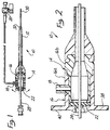
- a splittable introducer sheath and valve assembly is depicted in partially cutaway side view.
- Valve and sheath assembly 10 comprise a splittable sheath 12 connected, coupled or extending from a splittable hemostatic valve assembly 14.
- Valve assembly 14 in turn is comprised of a valve body 16, an intravenous sidearm 18 with a sidearm of valve 20.
- the details of the design of sidearm valve 20 and to a certain extent sidearm 18 are largely inconsequential to the present invention and therefore will not be further described except insofar as necessary to illustrate the invention.
- Hemostatic valve assembly 14 is shown in Figure 1 in cutaway view exposing the interior of valve 16 which includes a valve membrane 22.
- valve membrane 22 is a self-healing membrane through which a lead or catheter may be introduced without leakage between membrane 22 and leads or lead 24 such as shown in the partially cutaway view of Figure 2 depicted in expanded scale.
- Valve body 16 in the illustrated embodiment is comprised of two sections 16a and b which are bonded together after assembly.
- a conventional dilator 28 is shown as disposed through valve assembly 14 and sheath 12 having a tapered tip 30 extending from the distal end 32 of sheath 12.
- the artery or vessel is punctured with a needle into which a guidewire is placed.
- the needle removed and then dilator and sheath assembly 12 advanced on the guidewire into the vessel.
- the guidewire will extend through valve assembly 14 and be sealed by means of membrane 22.
- the guidewires and TEFLON dilator are then removed leaving the flexible sheath assembly 10 in place. However virtually no bleeding occurs since the entire assembly is sealed by self-healing membrane 22.
- one or more leads or catheters as suggested in Figure 2 can be introduced, removed and reintroduced and manipulated without any significant possibility of bleeding, clotting, risk of air embolism or repeated sheath insertion related trauma since once inserted sheath assembly 10 is in place regardless of the number of leads or catheters inserted and removed throughout the operation.
- valve body 16 and at least a portion of sheath 12 may be made larger than normal to allow a more loose fit between the interior surfaces of introducer sheath assembly 10 and leads or catheters 24 and 26, since blood sealing between the lead or catheter and sheath 12 is not required. This allows leads or catheters 24 and 26 to be introduced and removed from introducer sheath assembly 10 with less friction or interference with assembly 10 and with each other. Therefore the lead can be manipulated much easier.
- valve assembly 14 and sheath 12 may be fabricated according to any structure or out of any material now known to the art or later devised without departing from the scope of the invention.
- sheath 12 may be integrally molded or east with valve assembly, may be adhesively affixed thereto, may be compression fitted, slip fit, threaded, or connected in any manner desired to valve assembly 14 consistent with the teachings of the present invention.
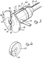
- FIG. 3 illustrates in enlarged scale a rear perspective view of introducer sheath assembly 10.
- both valve assembly 14 and sheath 12 are splittable or have a peel away construction. Again, the detailed nature by which such splittable structure is implemented or how peel-away feature is realized is not critical to the invention. Any method now known by which such sheaths 12 and valve assemblies 14 may be split or separated may be employed.
- sheath 12 and valve assembly 14 are shown as integrally fabricated and having a pair of longitudinal score lines 34 and 36 defined along their axial length. Score lines 34 and 36 are shown as being diametrically opposed from each other across the cross section of introducer sheath 10. Intravenous sidearm 18 is depicted in Figure 3 as being disposed between score lines 34 and 36 interlying surface between them. Score lines 34 and 36 are shown as having a V-shaped cross section but have such a shape and depth as to permit the entire length of introducer sheath 10 to be manually separated. It is contemplated that at the end of the operation the physician will grasp opposing flange portions 38 and 40 to peel them apart while pulling out the sheath and holding the lead.
- valve body 16 This will cause valve body 16 to tear along a section line depicted by dotted lines 42 through the body of valve assembly 14. Both body portions 16a and b may be scored to facilitate this tearing. In addition the bonding of the body portions 16a and 16b assists in tearing the inner body portion as the outer body portion is being torn along its corresponding tear line. The portions become through the bonding as a single body and the fracture or tear propagates from the outer body portion through the inner body portion. Membrane 22 has a weak line or score line and can easily be removed from the lead.
- flanges 38 and 40 are formed in two halves having diametrically opposing slots 44 and 46 aligned with score lines 34 and 36 defined into valve body 16.
- score lines 34 and 36 will be continued through flanges 38 and 40 to provide deep scores instead of open slots 44 and 46.
- valve body 16 is peeled apart with separation continuing through any transition portion 48 between valve body 16 and sheath 12 and on along the longitudinal length of sheath 12.
- Sheath 12 is then removed and peeled followed by additional removal of sheath 12 from the puncture site and peeling of the removed portions until the entire valve and introducer sheath assembly 10 of Figure 1 has been split and removed from the lead or catheter, which is then permanently implanted into the puncture site and with which the surrounding tissue makes a blood tight seal.
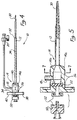
- splittable hemostatic valve assembly 14 is integrally molded or made separable from splittable sheath 12 and fitted at its proximal end with a dilator head fitting 50.
- Dilator head fitting 50 as shown in enlarged view in Figure 5 is secured to valve assembly 14 by means of a conventional Luer lock 52.
- the score line 34 on sheath 12 continues along sheath 12 into split body portions 14a and 14b which comprise the body of valve assembly 14.
- Valve membrane 22, disposed within valve assembly 14, is also provided with a Y-shaped incision 54 as best depicted in the perspective view of Figure 6 to facilitate opening and tearing of membrane 22 when valve body halves 14a and 14b are separated.
- valve halves 14a and 14b are temporarily fixed together by means of tearable single-sided adhesive tape 56.
- the binding of the body portions and the hemostatic membrane need not be excessively sturdy since the device is used at low pressures, 5-10 mm Hg and its use is typically of only 10-30 minutes duration.
- the long leg of the Y shape incision into or through membrane 22 may or may not extend to the periphery of membrane 22 as may be needed to facilitate its tearing or cutting.
- the practicing physician may then take a scalpel and easily cut tape 56 along the split line 34 and valve assembly 14 thereby separating the valve body portions 14a and 14b. As described above with the body portions 14a and 14b separated, sheath 12, which is integral, is then readily split along score line 34.
- Valve body 14 may be manufactured from valve body portions 14a and 14b in a number of alternative forms.
- Figure 7a and 7b wherein valve body 14 is generally split into two halves, an upper half 14b and a lower half 14a.
- Lower half 14a is provided with an interior circumferential lip 58a which slip fits into an exterior circumferential lip 58b defined in upper body half 14b.
- the two body halves, 14a and 14b as shown in Figure 7, which is a perpendicular cross-sectional view taken through section lines 7-7 of Figure 5, are then held together using tape 56. Once the tape is cut, the two body halves may then be manually separated as depicted in Figure 7b. While assembled, however, valve assembly 14 provides a water-tight or blood-tight valve assembly.
- FIG. 8 Another embodiment of the body of valve assembly 14 is depicted in the perpendicular cross-sectional view of Figure 8 as would also be seen through section line 7-7 of Figure 5.
- lower body portion 14a comprises a rectangular box
- upper body portion 14b is formed like a lid covering and seals the box-shape of body portion 14a.
- the outer circumferential seal 60a is provided on the lower body portion 14a while the inner circumferential seal 60b is defined on the upper lid body portion 14b, which is the conceptional reverse of the embodiment of Figure 7.
- Figures 9a and 9b illustrate yet another embodiment in which lower body portion 14a again defines a box-like shape and is coupled to upper body portion 14b acting as a lid, the two portions comprising an interior tongue and groove snap-fit seal.
- a groove 62a is defined in lower body portion 14a while a mating tongue 62b is provided in upper lip portion 14b.
- a cut-out recess 64 is formed in a least one position along line 34 wherein the surgeon can insert a scalpel or tool to pry body portions 14a and 14b apart.
- valve body 14 is depicted in perpendicular cross-sectional view of Figure 10, again as would be seen through section line 7-7 of Figure 5.
- separation between body portions 14a and 14b occurs generally along the mid-portion of lateral sides 66 of valve body 14 and are defined by providing a knife edge seal 68 in the one body portion, such as lower body portion 14a, and a conforming groove 70 in the opposing body portion, such upper portion 14b.
- portions 14a and 14b may be held together by an exterior tape 56 or may have a snap-fit facilitated by an expanded head 72 below knife edge 78 which is accommodated by a snap-fit conforming interior shape of groove 70.
- valve assembly 14 may be manufactured as separate halves and then be temporarily joined together with or without the aid of an exterior fastening means such as tape, friable spots of adhesive disposed in the joints between body portions 14a and 14b, or various compression fitting seals, some of which have been depicted by way of illustration in Figures 7-10.
- an exterior fastening means such as tape, friable spots of adhesive disposed in the joints between body portions 14a and 14b, or various compression fitting seals, some of which have been depicted by way of illustration in Figures 7-10.
Landscapes
- Health & Medical Sciences (AREA)
- Life Sciences & Earth Sciences (AREA)
- Hematology (AREA)
- Animal Behavior & Ethology (AREA)
- Engineering & Computer Science (AREA)
- Anesthesiology (AREA)
- Biomedical Technology (AREA)
- Heart & Thoracic Surgery (AREA)
- Biophysics (AREA)
- Pulmonology (AREA)
- General Health & Medical Sciences (AREA)
- Public Health (AREA)
- Veterinary Medicine (AREA)
- Infusion, Injection, And Reservoir Apparatuses (AREA)
- Materials For Medical Uses (AREA)
- Prostheses (AREA)
- Media Introduction/Drainage Providing Device (AREA)
Claims (10)
- Vorrichtung zur Verwendung für eine vaskuläre Implantation einer Leitung oder eines Katheters, umfassend:eine einstückige, trennbare Einführhülle (12), welche zur Anordnung bei einem Körperlumen angepaßt ist; undein hemostatisches einstückiges, trennbares Ventil (14), welches mit der Einführhülle (12) verbunden ist, wobei das hemostatische Ventil (14) dazu dient, die Leitung bzw. den Katheter innerhalb des hemostatischen Ventils (14) abzudichten, um ein Bluten und ein Eindringen von Luft in das Körperlumen zu verhindern, wenn die Leitung bzw. der Katheter in das Körperlumen eingeführt werden;
dadurch gekennzeichnet, daßdie Vorrichtung ein Mittel umfaßt, welches ein Entfernen der einstückigen, trennbaren Einführhülle (12) und des hemostatischen einstückigen, trennbaren Ventils (14) zusammen als eine Einheit von der Leitung bzw. dem Katheter ermöglichen, ohne daß die trennbare Einführhülle (12) bzw. das hemostatische trennbare Ventil (14) über ein Ende der Leitung bzw. des Katheters gleiten. - Vorrichtung nach Anspruch 1, ferner dadurch gekennzeichnet, daß das Mittel zum Entfernen des hemostatischen Ventils und der Einführhülle eine Einrichtung ist, welche die Einführhülle und das hemostatische Ventil von der Leitung bzw. dem Katheter, welche hindurchlaufend angeordnet sind, abtrennt.
- Vorrichtung nach Anspruch 1, ferner dadurch gekennzeichnet, daß das Mittel zum Entfernen der Einführhülle und des hemostatischen Ventils eine Einrichtung ist, welche die Einführhülle und das hemostatische Ventil von der Leitung bzw. dem Katheter, welche hindurchlaufend angeordnet sind, wegschält.
- Vorrichtung nach einem der vorhergehenden Ansprüche, wobei das Mittel zum Entfernen des hemostatischen Ventils und der Einführhülle eine in dem hemostatischen Ventil und der Einführhülle definierte Kerblinie (34) ist, entlang welcher das hemostatische Ventil und die Einführhülle getrennt werden können.
- Vorrichtung nach Anspruch 4, ferner dadurch gekennzeichnet, daß die Kerblinie ein Paar diametral gegenüberliegender Kerblinien umfaßt, welche in dem hemostatischen Ventil und der Einführhülle definiert sind.
- Vorrichtung nach Anspruch 4 oder Anspruch 5, ferner dadurch gekennzeichnet, daß die Kerblinie (34) entlang der Longitudinallänge des hemostatischen Ventils und der Einführhülle angeordnet ist.
- Vorrichtung nach einem der vorhergehenden Ansprüche, ferner dadurch gekennzeichnet, daß das hemostatische Ventil (14) eine selbstschließende Membran (22) umfaßt.
- Vorrichtung nach einem der vorhergehenden Ansprüche, ferner dadurch gekennzeichnet, daß das hemostatische Ventil (14) und die Hülle (12) derart angeordnet und aufgebaut sind, daß sie die Einführung vielfacher Leitungen bzw. Katheter ermöglichen.
- Vorrichtung nach Anspruch 7 oder 8, wobei das hemostatische Ventil (14) die wiederschließbare Membran (22) umfaßt, und wobei das Mittel zum Entfernen des hemostatischen Ventils einen Schnitt (54) in der wiederschließbaren Membran umfaßt, um ein Abtrennen der Membran zu erleichtern.
- Vorrichtung nach Anspruch 9, wobei der Schnitt (54) ein Y-förmiger Schnitt ist, welcher sich zumindest teilweise über die Membran (22) erstreckt, wobei der Schnittpunkt dieses Y-förmigen Schnitts etwa nahe der Mitte der Membran liegt, und sich ein Schenkel des Y in Richtung des Umfangs der Membran in einer Richtung erstreckt, entlang welcher die Membran trennbar ist.
Priority Applications (1)
| Application Number | Priority Date | Filing Date | Title |
|---|---|---|---|
| EP99114016A EP0948970A3 (de) | 1991-07-09 | 1992-07-06 | Teilbare Hüllenanordnung |
Applications Claiming Priority (5)
| Application Number | Priority Date | Filing Date | Title |
|---|---|---|---|
| US07727191 US5125904B1 (en) | 1991-07-09 | 1991-07-09 | Splittable hemostatic valve sheath and the method for using the same |
| US727191 | 1991-07-09 | ||
| US905045 | 1992-06-26 | ||
| US07/905,045 US5312355A (en) | 1991-07-09 | 1992-06-26 | Splittable hemostatic valve and sheath and the method for using the same |
| PCT/US1992/005666 WO1993000947A1 (en) | 1991-07-09 | 1992-07-06 | Splittable sheath assembly and method for using |
Related Child Applications (1)
| Application Number | Title | Priority Date | Filing Date |
|---|---|---|---|
| EP99114016A Division EP0948970A3 (de) | 1991-07-09 | 1992-07-06 | Teilbare Hüllenanordnung |
Publications (3)
| Publication Number | Publication Date |
|---|---|
| EP0593685A1 EP0593685A1 (de) | 1994-04-27 |
| EP0593685A4 EP0593685A4 (de) | 1995-06-28 |
| EP0593685B1 true EP0593685B1 (de) | 2000-02-16 |
Family
ID=27111469
Family Applications (2)
| Application Number | Title | Priority Date | Filing Date |
|---|---|---|---|
| EP92919181A Expired - Lifetime EP0593685B1 (de) | 1991-07-09 | 1992-07-06 | Teilbare hüllenanordnung |
| EP99114016A Withdrawn EP0948970A3 (de) | 1991-07-09 | 1992-07-06 | Teilbare Hüllenanordnung |
Family Applications After (1)
| Application Number | Title | Priority Date | Filing Date |
|---|---|---|---|
| EP99114016A Withdrawn EP0948970A3 (de) | 1991-07-09 | 1992-07-06 | Teilbare Hüllenanordnung |
Country Status (8)
| Country | Link |
|---|---|
| US (1) | US5312355A (de) |
| EP (2) | EP0593685B1 (de) |
| JP (1) | JP2001527425A (de) |
| AT (1) | ATE189774T1 (de) |
| CA (1) | CA2112394C (de) |
| DE (1) | DE69230689T2 (de) |
| ES (1) | ES2146588T3 (de) |
| WO (1) | WO1993000947A1 (de) |
Families Citing this family (192)
| Publication number | Priority date | Publication date | Assignee | Title |
|---|---|---|---|---|
| US5766151A (en) * | 1991-07-16 | 1998-06-16 | Heartport, Inc. | Endovascular system for arresting the heart |
| EP0631793A1 (de) * | 1993-06-30 | 1995-01-04 | Cook Incorporated | Auftrennbares hemostatisches Ventil und desser Anwendungsmethode mit einer auftrennbaren Einführungshülse |
| US6277107B1 (en) * | 1993-08-13 | 2001-08-21 | Daig Corporation | Guiding introducer for introducing medical devices into the coronary sinus and process for using same |
| US5653730A (en) * | 1993-09-28 | 1997-08-05 | Hemodynamics, Inc. | Surface opening adhesive sealer |
| US5759194A (en) * | 1993-09-28 | 1998-06-02 | Hemodynamics, Inc. | Vascular patch applicator |
| US5843124A (en) | 1993-09-28 | 1998-12-01 | Hemodynamics, Inc. | Surface opening adhesive sealer |
| US5383899A (en) * | 1993-09-28 | 1995-01-24 | Hammerslag; Julius G. | Method of using a surface opening adhesive sealer |
| US5814029A (en) * | 1994-11-03 | 1998-09-29 | Daig Corporation | Guiding introducer system for use in ablation and mapping procedures in the left ventricle |
| US6287322B1 (en) * | 1995-12-07 | 2001-09-11 | Loma Linda University Medical Center | Tissue opening locator and everter and method |
| US6228052B1 (en) * | 1996-02-29 | 2001-05-08 | Medtronic Inc. | Dilator for introducer system having injection port |
| US5824001A (en) * | 1996-06-10 | 1998-10-20 | Becton Dickinson And Company | Radially vented flashback chamber and plug assembly |
| US6645178B1 (en) | 1997-04-21 | 2003-11-11 | Larry G. Junker | Apparatus for inserting medical device |
| US6038472A (en) * | 1997-04-29 | 2000-03-14 | Medtronic, Inc. | Implantable defibrillator and lead system |
| US6083207A (en) * | 1998-12-08 | 2000-07-04 | Daig Corporation | Partitioned hemostasis valve system |
| US6758854B1 (en) | 1997-05-09 | 2004-07-06 | St. Jude Medical | Splittable occlusion balloon sheath and process of use |
| US6251109B1 (en) | 1997-06-27 | 2001-06-26 | Daig Corporation | Process and device for the treatment of atrial arrhythmia |
| US5938660A (en) * | 1997-06-27 | 1999-08-17 | Daig Corporation | Process and device for the treatment of atrial arrhythmia |
| US6213988B1 (en) | 1998-02-10 | 2001-04-10 | Medtronic, Inc. | Introducer with external hemostasis clip |
| US6159198A (en) * | 1998-07-16 | 2000-12-12 | Medtronic, Inc. | Introducer system |
| US6196995B1 (en) | 1998-09-30 | 2001-03-06 | Medtronic Ave, Inc. | Reinforced edge exchange catheter |
| US6623460B1 (en) * | 1998-12-08 | 2003-09-23 | St. Jude Medical, Daig Division | Partitioned hemostasis valve system |
| US6808509B1 (en) | 1999-04-22 | 2004-10-26 | Scimed Life Systems, Inc. | Valved introducer sheath and related methods |
| JP4244552B2 (ja) * | 1999-06-25 | 2009-03-25 | セイント・ジュード・メディカル・エイトリアル・フィブリレイション・ディビジョン・インコーポレイテッド | 引き裂き可能な閉塞バルーンシースおよび使用方法 |
| US7303552B1 (en) * | 1999-10-29 | 2007-12-04 | Boston Scientific Scimed, Inc. | Split valve for peel-away sheath |
| DE19955445C2 (de) * | 1999-11-18 | 2002-10-17 | Joline Gmbh & Co Kg | Vorrichtung mit hämostatischem Ventil zum Einführen von Gegenständen in die Blutbahn eines Patienten |
| US6363273B1 (en) | 1999-12-22 | 2002-03-26 | Codman & Shurtleff, Inc. | Introducer element and method of using same |
| AU2741801A (en) | 1999-12-30 | 2001-07-16 | Cook Vascular Incorporated | Splittable medical valve |
| US7101353B2 (en) * | 1999-12-30 | 2006-09-05 | Cook Vascular Incorporated | Splittable medical valve |
| US6836687B2 (en) * | 2000-03-31 | 2004-12-28 | Medtronic, Inc. | Method and system for delivery of a medical electrical lead within a venous system |
| US6733500B2 (en) | 2000-03-31 | 2004-05-11 | Medtronic, Inc. | Method and system for delivering a medical electrical lead within a venous system |
| US7497844B2 (en) * | 2000-03-31 | 2009-03-03 | Medtronic, Inc. | System and method for positioning implantable medical devices within coronary veins |
| EP1267986B1 (de) | 2000-03-31 | 2006-05-10 | Medtronic, Inc. | Lenkmechanismus |
| US6497681B1 (en) | 2000-06-02 | 2002-12-24 | Thomas Medical Products, Inc. | Device and method for holding and maintaining the position of a medical device such as a cardiac pacing lead or other intravascular instrument and for facilitating removal of a peelable or splittable introducer sheath |
| US6840246B2 (en) * | 2000-06-20 | 2005-01-11 | University Of Maryland, Baltimore | Apparatuses and methods for performing minimally invasive diagnostic and surgical procedures inside of a beating heart |
| US6712789B1 (en) | 2000-07-13 | 2004-03-30 | Medamicus, Inc. | Introducer having a movable valve assembly with removable side port |
| US6890342B2 (en) | 2000-08-02 | 2005-05-10 | Loma Linda University | Method and apparatus for closing vascular puncture using hemostatic material |
| DE10100102C2 (de) * | 2001-01-03 | 2003-05-28 | Eckert Rosemarie | Katheterpunktionsbesteck |
| US7025746B2 (en) * | 2001-12-26 | 2006-04-11 | Yale University | Vascular access device |
| US6692464B2 (en) | 2002-02-28 | 2004-02-17 | Cook, Incorporated | T-fitting for splittable sheath |
| US7192433B2 (en) * | 2002-03-15 | 2007-03-20 | Oscor Inc. | Locking vascular introducer assembly with adjustable hemostatic seal |
| US7588581B2 (en) * | 2002-03-26 | 2009-09-15 | Medtronic, Inc. | Placement of chronic micro-catheter device and method |
| WO2003105697A1 (en) * | 2002-06-14 | 2003-12-24 | Loma Linda University Medical Center | Vascular wound closure device and method |
| DE20210394U1 (de) | 2002-07-04 | 2002-09-12 | B. Braun Melsungen Ag, 34212 Melsungen | Kathetereinführvorrichtung |
| US8048061B2 (en) * | 2002-07-31 | 2011-11-01 | Pressure Products Medical Supplies, Inc. | Tapered fitting for an introducer coupled to a hemostatic valve |
| ATE527014T1 (de) * | 2002-08-29 | 2011-10-15 | Medical Components Inc | Lösbar arretierbarer dilatator und schleusenanordnung |
| US7422571B2 (en) | 2002-08-29 | 2008-09-09 | Medical Components, Inc. | Releasably locking dilator and sheath assembly |
| US6966896B2 (en) * | 2002-09-04 | 2005-11-22 | Paul A. Kurth | Introducer and hemostatic valve combination and method of using the same |
| US20040059296A1 (en) * | 2002-09-19 | 2004-03-25 | Godfrey Mark W. | Peripherally inserted peel away introducer cannula assembly with peel away valve |
| US9480839B2 (en) | 2002-09-24 | 2016-11-01 | Medtronic, Inc. | Lead delivery device and method |
| US8920432B2 (en) | 2002-09-24 | 2014-12-30 | Medtronic, Inc. | Lead delivery device and method |
| US9636499B2 (en) | 2002-09-24 | 2017-05-02 | Medtronic, Inc. | Lead delivery device and method |
| US9849279B2 (en) | 2008-06-27 | 2017-12-26 | Medtronic, Inc. | Lead delivery device and method |
| US20060009827A1 (en) | 2002-11-15 | 2006-01-12 | Kurth Paul A | Method and apparatus for anchoring of pacing leads |
| US20050020981A1 (en) * | 2003-06-18 | 2005-01-27 | Kurth Paul A. | Method and apparatus with a splittable hemostatic valve with a variable aperture |
| US20040267202A1 (en) * | 2003-06-26 | 2004-12-30 | Potter Daniel J. | Tearable hemostasis valve and splittable sheath |
| US7789877B2 (en) * | 2003-07-02 | 2010-09-07 | St. Jude Medical, Atrial Fibrillation Division, Inc. | Ablation catheter electrode arrangement |
| US7985232B2 (en) * | 2003-07-08 | 2011-07-26 | St. Jude Medical, Atrial Fibrillation Division, Inc. | Detachable hemostasis valve and splittable sheath assembly |
| AU2003249557A1 (en) * | 2003-08-07 | 2005-02-25 | Eran Hirszowicz | Indwelling device |
| ATE502580T1 (de) | 2003-08-14 | 2011-04-15 | Univ Loma Linda Med | Vorrichtung zum verschluss von gefässwunden |
| US7229437B2 (en) * | 2003-09-22 | 2007-06-12 | St. Jude Medical, Atrial Fibrillation Division, Inc. | Medical device having integral traces and formed electrodes |
| US7234225B2 (en) * | 2003-09-22 | 2007-06-26 | St. Jude Medical, Atrial Fibrillation Division, Inc. | Method for manufacturing medical device having embedded traces and formed electrodes |
| US8147486B2 (en) * | 2003-09-22 | 2012-04-03 | St. Jude Medical, Atrial Fibrillation Division, Inc. | Medical device with flexible printed circuit |
| DE102004011217B4 (de) * | 2004-03-04 | 2006-11-30 | Dr. Osypka Gmbh | Vorrichtung zum Implantieren einer Herzschrittmacher - und/oder Defibrillations-Elektrode |
| US7594911B2 (en) | 2004-03-18 | 2009-09-29 | C. R. Bard, Inc. | Connector system for a proximally trimmable catheter |
| US7854731B2 (en) | 2004-03-18 | 2010-12-21 | C. R. Bard, Inc. | Valved catheter |
| US7094218B2 (en) | 2004-03-18 | 2006-08-22 | C. R. Bard, Inc. | Valved catheter |
| US7578803B2 (en) | 2004-03-18 | 2009-08-25 | C. R. Bard, Inc. | Multifunction adaptor for an open-ended catheter |
| US7594910B2 (en) | 2004-03-18 | 2009-09-29 | C. R. Bard, Inc. | Catheter connector |
| US8083728B2 (en) | 2004-03-18 | 2011-12-27 | C. R. Bard, Inc. | Multifunction adaptor for an open-ended catheter |
| USD532513S1 (en) | 2004-03-19 | 2006-11-21 | Galt Medical Corporation | Handle for an introducer sheath |
| US7377915B2 (en) | 2004-04-01 | 2008-05-27 | C. R. Bard, Inc. | Catheter connector system |
| CN1946451A (zh) | 2004-04-30 | 2007-04-11 | C.R.巴德有限公司 | 静脉插管的阀式护套导入器 |
| US7524305B2 (en) * | 2004-09-07 | 2009-04-28 | B. Braun Medical, Inc. | Peel-away introducer and method for making the same |
| US20060217664A1 (en) * | 2004-11-15 | 2006-09-28 | Hattler Brack G | Telescoping vascular dilator |
| US8403890B2 (en) | 2004-11-29 | 2013-03-26 | C. R. Bard, Inc. | Reduced friction catheter introducer and method of manufacturing and using the same |
| US8926564B2 (en) | 2004-11-29 | 2015-01-06 | C. R. Bard, Inc. | Catheter introducer including a valve and valve actuator |
| US8932260B2 (en) | 2004-11-29 | 2015-01-13 | C. R. Bard, Inc. | Reduced-friction catheter introducer and method of manufacturing and using the same |
| US9597483B2 (en) * | 2004-11-29 | 2017-03-21 | C. R. Bard, Inc. | Reduced-friction catheter introducer and method of manufacturing and using the same |
| US8371555B2 (en) * | 2005-01-04 | 2013-02-12 | Pacesetter, Inc. | Splittable hemostasis valve |
| EP2366422A1 (de) | 2005-03-30 | 2011-09-21 | Access Scientific, Inc. | Gefässzugangsgerät |
| US7780723B2 (en) | 2005-06-13 | 2010-08-24 | Edwards Lifesciences Corporation | Heart valve delivery system |
| US7875019B2 (en) | 2005-06-20 | 2011-01-25 | C. R. Bard, Inc. | Connection system for multi-lumen catheter |
| ATE499882T1 (de) * | 2005-10-05 | 2011-03-15 | Univ Loma Linda Med | Gefässwundverschluss-vorrichtung |
| US7637902B2 (en) * | 2005-11-23 | 2009-12-29 | Medtronic, Inc. | Slittable and peelable sheaths and methods for making and using them |
| US7632254B1 (en) * | 2006-01-23 | 2009-12-15 | Pacesetter, Inc. | Device for splitting the tubular body of a catheter or sheath |
| JP5324422B2 (ja) * | 2006-03-20 | 2013-10-23 | メドトロニック,インコーポレイテッド | 除去可能な弁及び弁の製造方法 |
| US8308691B2 (en) | 2006-11-03 | 2012-11-13 | B. Braun Melsungen Ag | Catheter assembly and components thereof |
| US9433492B2 (en) * | 2006-09-20 | 2016-09-06 | Boarad of Regents of the University of Nebraska | Method and device for facilitating surgical access to a body area |
| JP4994775B2 (ja) | 2006-10-12 | 2012-08-08 | 日本コヴィディエン株式会社 | 針先保護具 |
| JP5118148B2 (ja) * | 2006-11-08 | 2013-01-16 | カーディアック ペースメイカーズ, インコーポレイテッド | 分離式止血ハブ |
| US8012143B1 (en) * | 2006-12-12 | 2011-09-06 | Pacesetter, Inc. | Intrapericardial delivery tools and methods |
| US7922696B2 (en) | 2007-01-24 | 2011-04-12 | Access Scientific, Inc. | Access device |
| EP2486880A3 (de) | 2007-04-18 | 2013-01-16 | Access Scientific, Inc. | Zugangsvorrichtung |
| EP2486951B1 (de) | 2007-04-18 | 2016-05-25 | Access Scientific, Inc. | Zugangsvorrichtung |
| AU2008268632B2 (en) * | 2007-06-22 | 2013-10-17 | Medical Components, Inc. | Tearaway sheath assembly with hemostasis valve |
| WO2009003044A1 (en) | 2007-06-26 | 2008-12-31 | Avalon Laboratories, Llc | Coaxial venal cannula |
| US8142446B2 (en) * | 2007-09-18 | 2012-03-27 | Sorin Crm S.A.S. | Toolkit for implanting an intracorporeal lead such as for cardiac pacing or sensing |
| EP2195063B1 (de) * | 2007-09-18 | 2019-08-07 | Medical Components, Inc. | Abreissbare schleusenanordnung mit spalt-hämostaseventil |
| WO2009041968A1 (en) * | 2007-09-27 | 2009-04-02 | Cryocath Technologies Inc. | Accessory sleeve for a medical device |
| CN101903062A (zh) | 2007-10-19 | 2010-12-01 | C·R·巴德股份有限公司 | 具有成形的远侧区域的导引装置 |
| USD601242S1 (en) | 2008-03-14 | 2009-09-29 | Access Scientific, Inc. | Access device |
| US8202251B2 (en) | 2008-03-14 | 2012-06-19 | Access Scientific, Inc. | Access device |
| WO2009114456A1 (en) * | 2008-03-14 | 2009-09-17 | Medical Components, Inc. | Tearaway introducer sheath with hemostasis valve |
| USD615201S1 (en) | 2008-03-14 | 2010-05-04 | Access Scientific, Inc. | Combined guide wire cap and track |
| CA2718496A1 (en) | 2008-03-14 | 2009-09-17 | Access Scientific, Inc. | Access device |
| USD594981S1 (en) | 2008-03-14 | 2009-06-23 | Access Scientific, Inc. | Needle hub |
| US11931523B2 (en) | 2008-06-27 | 2024-03-19 | Medtronic, Inc. | Lead delivery device and method |
| US9775990B2 (en) | 2008-06-27 | 2017-10-03 | Medtronic, Inc. | Lead delivery device and method |
| US9775989B2 (en) | 2008-06-27 | 2017-10-03 | Medtronic, Inc. | Lead delivery device and method |
| USD601243S1 (en) | 2008-09-10 | 2009-09-29 | Access Scientific, Inc. | Access device |
| USD600793S1 (en) | 2008-09-10 | 2009-09-22 | Access Scientific, Inc. | Access device |
| US7824375B2 (en) * | 2008-10-09 | 2010-11-02 | Pacesetter, Inc. | Slittable delivery device for the delivery of a cardiac surgical device |
| US8043263B2 (en) * | 2008-10-09 | 2011-10-25 | Pacesetter, Inc. | Slittable delivery device assembly for the delivery of a cardiac surgical device |
| EP2179763A1 (de) | 2008-10-22 | 2010-04-28 | Greatbatch Ltd. | Auftrennbares Einführinstrument mit Ventil |
| US20110218496A1 (en) * | 2008-11-12 | 2011-09-08 | Steven F Bierman | Access device |
| KR20120030087A (ko) | 2009-05-12 | 2012-03-27 | 엑세스 싸이언티픽, 인크. | 밸브를 구비한 액세스 장치 |
| WO2010151825A1 (en) | 2009-06-26 | 2010-12-29 | C. R. Bard, Inc. | Proximally trimmable catheter including pre-attached bifurcation and related methods |
| US8317754B2 (en) * | 2009-07-06 | 2012-11-27 | AUST Development, LLC | Valves and hubs for tubular devices and methods for making and using them |
| US8512293B2 (en) * | 2009-08-13 | 2013-08-20 | AUST Development, LLC | Valves and hubs for tubular medical devices and methods for making and using them |
| JP5519988B2 (ja) * | 2009-09-29 | 2014-06-11 | テルモ株式会社 | 弁体、イントロデューサシースおよびイントロデューサ組立体の製造方法 |
| US20110190697A1 (en) | 2010-02-03 | 2011-08-04 | Circulite, Inc. | Vascular introducers having an expandable section |
| WO2011097639A2 (en) | 2010-02-08 | 2011-08-11 | Access Scientific, Inc. | Access device |
| US9192752B2 (en) | 2010-07-05 | 2015-11-24 | AUST Development, LLC | Serial valves and hubs for tubular devices and methods for making and using them |
| US8348927B2 (en) | 2010-07-30 | 2013-01-08 | Medtronic, Inc. | Tools and methods related to catheter delivery |
| US8298209B2 (en) | 2010-07-30 | 2012-10-30 | Medtronic, Inc. | Sealing for medical devices/instruments |
| US8394079B2 (en) | 2010-07-30 | 2013-03-12 | Medtronic, Inc. | Medical delivery systems and apparatus |
| US8348926B2 (en) | 2010-07-30 | 2013-01-08 | Medtronic, Inc. | Catheter apparatus |
| US9744349B2 (en) | 2011-02-10 | 2017-08-29 | Respicardia, Inc. | Medical lead and implantation |
| EP2517751B8 (de) | 2011-04-27 | 2018-02-28 | Kpr U.S., Llc | Sicherheits-IV-Katheteranordnungen |
| US20120296313A1 (en) * | 2011-05-20 | 2012-11-22 | Abbott Cardiovascular Systems Inc. | Drug Coated Balloon Hemostatic Valve Insertion/Balloon Sheath |
| US8753313B2 (en) | 2011-07-22 | 2014-06-17 | Greatbatch Ltd. | Introducer handle notch design/concept |
| WO2013026045A1 (en) | 2011-08-17 | 2013-02-21 | Access Scientific, Inc. | Access device with valve |
| WO2013048975A1 (en) | 2011-09-26 | 2013-04-04 | Covidien Lp | Safety catheter |
| EP2760521B1 (de) | 2011-09-26 | 2016-01-06 | Covidien LP | Sicherheits-iv-katheter und nadelanordnung |
| WO2013056223A1 (en) | 2011-10-14 | 2013-04-18 | Covidien Lp | Safety iv catheter assembly |
| US11420033B2 (en) | 2013-01-23 | 2022-08-23 | C. R. Bard, Inc. | Low-profile single and dual vascular access device |
| US20160001042A1 (en) | 2013-03-14 | 2016-01-07 | Pressure Products Medical Supplies Inc. | Hybrid Lateral Vein Introducer |
| US9566087B2 (en) | 2013-03-15 | 2017-02-14 | Access Scientific, Llc | Vascular access device |
| US10556117B2 (en) | 2013-05-06 | 2020-02-11 | Medtronic, Inc. | Implantable cardioverter-defibrillator (ICD) system including substernal pacing lead |
| US20140330287A1 (en) | 2013-05-06 | 2014-11-06 | Medtronic, Inc. | Devices and techniques for anchoring an implantable medical device |
| US9717923B2 (en) | 2013-05-06 | 2017-08-01 | Medtronic, Inc. | Implantable medical device system having implantable cardioverter-defibrillator (ICD) system and substernal leadless pacing device |
| US10668270B2 (en) | 2013-05-06 | 2020-06-02 | Medtronic, Inc. | Substernal leadless electrical stimulation system |
| US9220913B2 (en) | 2013-05-06 | 2015-12-29 | Medtronics, Inc. | Multi-mode implantable medical device |
| US9717898B2 (en) | 2013-05-06 | 2017-08-01 | Medtronic, Inc. | Systems and methods for implanting a medical electrical lead |
| US10471267B2 (en) | 2013-05-06 | 2019-11-12 | Medtronic, Inc. | Implantable cardioverter-defibrillator (ICD) system including substernal lead |
| US10166017B2 (en) | 2013-08-05 | 2019-01-01 | Cook Medical Technologies Llc | Medical devices having a releasable tubular member and methods of using the same |
| US9155868B2 (en) | 2013-08-30 | 2015-10-13 | Medtronic, Inc. | Delivery catheter apparatus and methods |
| CA2921133A1 (en) | 2013-09-06 | 2015-03-12 | Boston Scientific Neuromodulation Corporation | Lead introducer for an implantable electrical stimulation system |
| AU2014315385B2 (en) | 2013-09-06 | 2017-06-22 | Boston Scientific Neuromodulation Corporation | Lead introducer for an implantable electrical stimulation system |
| US10434307B2 (en) | 2013-10-15 | 2019-10-08 | Medtronic, Inc. | Methods and devices for subcutaneous lead implantation |
| US10531893B2 (en) | 2013-11-12 | 2020-01-14 | Medtronic, Inc. | Extravascular implant tools with open sheath and implant techniques utilizing such tools |
| US10792490B2 (en) | 2013-11-12 | 2020-10-06 | Medtronic, Inc. | Open channel implant tools and implant techniques utilizing such tools |
| US10328268B2 (en) | 2014-09-04 | 2019-06-25 | AtaCor Medical, Inc. | Cardiac pacing |
| US10743960B2 (en) | 2014-09-04 | 2020-08-18 | AtaCor Medical, Inc. | Cardiac arrhythmia treatment devices and delivery |
| CA2959183C (en) | 2014-09-04 | 2023-10-10 | AtaCor Medical, Inc. | Receptacle for pacemaker lead |
| US9636505B2 (en) | 2014-11-24 | 2017-05-02 | AtaCor Medical, Inc. | Cardiac pacing sensing and control |
| US9636512B2 (en) | 2014-11-05 | 2017-05-02 | Medtronic, Inc. | Implantable cardioverter-defibrillator (ICD) system having multiple common polarity extravascular defibrillation electrodes |
| US10272227B2 (en) | 2014-11-07 | 2019-04-30 | C. R. Bard, Inc. | Connection system for tunneled catheters |
| US11097109B2 (en) | 2014-11-24 | 2021-08-24 | AtaCor Medical, Inc. | Cardiac pacing sensing and control |
| US11083491B2 (en) | 2014-12-09 | 2021-08-10 | Medtronic, Inc. | Extravascular implant tools utilizing a bore-in mechanism and implant techniques using such tools |
| US10729456B2 (en) | 2014-12-18 | 2020-08-04 | Medtronic, Inc. | Systems and methods for deploying an implantable medical electrical lead |
| US10349978B2 (en) | 2014-12-18 | 2019-07-16 | Medtronic, Inc. | Open channel implant tool with additional lumen and implant techniques utilizing such tools |
| EP3244960B1 (de) * | 2015-01-14 | 2024-01-10 | SurModics, Inc. | Einführungswerkzeug für medizinische vorrichtung |
| US9931109B2 (en) | 2015-02-13 | 2018-04-03 | Boston Scientific Neuromodulation Corporation | Retractor and tools for implantation of electrical stimulation leads and methods of using and manufacture |
| WO2016176211A1 (en) | 2015-04-28 | 2016-11-03 | Boston Scientific Neuromodulation Corporation | Systems and methods for making and using a lead introducer with a seal for an electrical stimulation system |
| WO2016176065A1 (en) | 2015-04-30 | 2016-11-03 | Access Scientific, Llc | Vascular access device |
| US11026788B2 (en) * | 2015-08-20 | 2021-06-08 | Edwards Lifesciences Corporation | Loader and retriever for transcatheter heart valve, and methods of crimping transcatheter heart valve |
| CN210750892U (zh) | 2015-08-24 | 2020-06-16 | 阿比奥梅德公司 | 用于将医疗装置插入到患者的血管中的引入器 |
| AU2017325722B2 (en) | 2016-09-16 | 2023-11-30 | Surmodics, Inc. | Lubricious insertion tools for medical devices and methods for using |
| IL308499B2 (en) | 2016-12-08 | 2024-11-01 | Abiomed Inc | A design technique for peel-off penetrative design |
| EP3585467B1 (de) * | 2017-02-23 | 2025-07-02 | Boston Scientific Scimed, Inc. | Ladewerkzeuge zur verwendung mit medizinischen vorrichtungen |
| WO2018191547A1 (en) | 2017-04-14 | 2018-10-18 | Access Scientific, Llc | Vascular access device |
| EP3672682B1 (de) | 2017-08-23 | 2024-04-03 | C. R. Bard, Inc. | Katheteranordnungen und verfahren dafür |
| US10543354B2 (en) * | 2017-09-27 | 2020-01-28 | Becton, Dickinson And Company | Peripheral intravenous catheters having flow diverting features |
| AU2018359898B2 (en) | 2017-11-06 | 2024-09-12 | Abiomed, Inc. | Peel away hemostasis valve |
| US10569059B2 (en) | 2018-03-01 | 2020-02-25 | Asspv, Llc | Guidewire retention device |
| SG11202011175QA (en) | 2018-05-16 | 2020-12-30 | Abiomed Inc | Peel-away sheath assembly |
| US11737656B2 (en) * | 2018-06-01 | 2023-08-29 | PatCom Medical Inc. | Catheter and tube introducer |
| ES3000010T3 (en) | 2018-08-13 | 2025-02-27 | Inari Medical Inc | System for treating embolism and associated devices and methods |
| AU2020226356B2 (en) | 2019-02-19 | 2022-12-08 | Boston Scientific Neuromodulation Corporation | Lead introducers and systems and methods including the lead introducers |
| US11559667B2 (en) | 2019-03-18 | 2023-01-24 | Makram R. Ebeid | Guidewire retaining accessory |
| CA3314271A1 (en) | 2019-05-29 | 2026-08-05 | AtaCor Medical, Inc. | Implantable electrical leads and associated delivery systems |
| US20210353907A1 (en) * | 2020-05-15 | 2021-11-18 | Medtronic, Inc. | Constructions for a deflectable shaft catheter |
| US11666771B2 (en) | 2020-05-29 | 2023-06-06 | AtaCor Medical, Inc. | Implantable electrical leads and associated delivery systems |
| US20260158257A1 (en) * | 2021-11-02 | 2026-06-11 | Becton, Dickinson And Company | Upper Arm Port |
| US12471896B2 (en) | 2021-11-24 | 2025-11-18 | AtaCor Medical, Inc. | Systems and methods for lead delivery |
| US11628277B1 (en) * | 2022-02-25 | 2023-04-18 | American Endoscopic Innovations, LLC | Devices, systems, and methods for holding medical devices |
| WO2023215779A2 (en) * | 2022-05-04 | 2023-11-09 | Inari Medical, Inc. | Dilator for vascular access systems, and associated devices and methods |
| CA3205437A1 (en) * | 2022-07-01 | 2024-01-01 | Zurn Industries, Llc | Relief valve assembly |
| EP4746792A1 (de) | 2023-10-02 | 2026-05-27 | Boston Scientific Neuromodulation Corporation | Leitungseinführer und systeme mit den leitungseinführern |
| WO2025133667A1 (en) | 2023-12-18 | 2025-06-26 | Sorin Crm Sas | Syringe adapter for fixation in rotation axis |
| WO2025240410A1 (en) * | 2024-05-13 | 2025-11-20 | Ep Dynamics, Inc. | Air blocks |
Family Cites Families (20)
| Publication number | Priority date | Publication date | Assignee | Title |
|---|---|---|---|---|
| US3677244A (en) * | 1969-08-04 | 1972-07-18 | Extracorporeal Med Spec | Removable catheter needle |
| US3653388A (en) * | 1969-12-04 | 1972-04-04 | Battelle Development Corp | Catheter insertion trocar |
| US4243050A (en) | 1977-12-13 | 1981-01-06 | Littleford Philip O | Method for inserting pacemaker electrodes and the like |
| US4345606A (en) | 1977-12-13 | 1982-08-24 | Littleford Philip O | Split sleeve introducers for pacemaker electrodes and the like |
| US4166469A (en) | 1977-12-13 | 1979-09-04 | Littleford Philip O | Apparatus and method for inserting an electrode |
| USRE31855F1 (en) | 1978-12-01 | 1986-08-19 | Tear apart cannula | |
| US4306562A (en) * | 1978-12-01 | 1981-12-22 | Cook, Inc. | Tear apart cannula |
| DE3140915A1 (de) * | 1980-10-18 | 1982-05-27 | Hans 3000 Hannover Haindl | Kathetersystem mit biegsamer kanuele aus kunststoff |
| US4411654A (en) | 1981-04-30 | 1983-10-25 | Baxter Travenol Laboratories, Inc. | Peelable catheter with securing ring and suture sleeve |
| US4345596A (en) * | 1981-12-23 | 1982-08-24 | Janis Marie Young | Arterial catherization device |
| US4596559A (en) * | 1984-11-02 | 1986-06-24 | Fleischhacker John J | Break-away handle for a catheter introducer set |
| JPS62101261A (ja) * | 1985-10-28 | 1987-05-11 | テルモ株式会社 | 医療器具導入用チユ−ブおよびそれを備えた医療器具導入用組立体 |
| JPS62133969A (ja) * | 1985-12-06 | 1987-06-17 | 日本シヤ−ウツド株式会社 | 血管内留置用使い捨てカテ−テル導入装置 |
| US4883468A (en) | 1987-04-08 | 1989-11-28 | Terumo Kabushiki Kaisha | Medical tool introduction cannula and method of manufacturing the same |
| US4772266A (en) * | 1987-05-04 | 1988-09-20 | Catheter Technology Corp. | Catheter dilator/sheath assembly and method |
| DE3721288C1 (en) * | 1987-06-27 | 1989-06-22 | Sterimed Gmbh | Sealing cuff for a catheter |
| US4921479A (en) * | 1987-10-02 | 1990-05-01 | Joseph Grayzel | Catheter sheath with longitudinal seam |
| US4960412A (en) * | 1988-04-15 | 1990-10-02 | Universal Medical Instrument Corp. | Catheter introducing system |
| DE3834600C1 (en) * | 1988-10-11 | 1989-12-21 | B. Braun Melsungen Ag, 3508 Melsungen, De | Puncturing and introduction device for elongate articles |
| US4983168A (en) | 1989-01-05 | 1991-01-08 | Catheter Technology Corporation | Medical layered peel away sheath and methods |
-
1992
- 1992-06-26 US US07/905,045 patent/US5312355A/en not_active Expired - Lifetime
- 1992-07-06 EP EP92919181A patent/EP0593685B1/de not_active Expired - Lifetime
- 1992-07-06 JP JP50237393A patent/JP2001527425A/ja not_active Ceased
- 1992-07-06 EP EP99114016A patent/EP0948970A3/de not_active Withdrawn
- 1992-07-06 ES ES92919181T patent/ES2146588T3/es not_active Expired - Lifetime
- 1992-07-06 AT AT92919181T patent/ATE189774T1/de not_active IP Right Cessation
- 1992-07-06 WO PCT/US1992/005666 patent/WO1993000947A1/en not_active Ceased
- 1992-07-06 DE DE69230689T patent/DE69230689T2/de not_active Expired - Lifetime
- 1992-07-06 CA CA002112394A patent/CA2112394C/en not_active Expired - Lifetime
Also Published As
| Publication number | Publication date |
|---|---|
| EP0593685A1 (de) | 1994-04-27 |
| US5312355A (en) | 1994-05-17 |
| ES2146588T3 (es) | 2000-08-16 |
| CA2112394C (en) | 1997-04-22 |
| DE69230689T2 (de) | 2000-10-26 |
| WO1993000947A1 (en) | 1993-01-21 |
| ATE189774T1 (de) | 2000-03-15 |
| CA2112394A1 (en) | 1993-01-21 |
| EP0948970A3 (de) | 1999-12-29 |
| EP0593685A4 (de) | 1995-06-28 |
| DE69230689D1 (de) | 2000-03-23 |
| EP0948970A2 (de) | 1999-10-13 |
| JP2001527425A (ja) | 2001-12-25 |
Similar Documents
| Publication | Publication Date | Title |
|---|---|---|
| US5312355A (en) | Splittable hemostatic valve and sheath and the method for using the same | |
| US5125904A (en) | Splittable hemostatic valve and sheath and the method for using the same | |
| EP0588996B1 (de) | Elektrodeneinfuehreinrichtung mit mechanish oeffnendem ventil | |
| EP0631793A1 (de) | Auftrennbares hemostatisches Ventil und desser Anwendungsmethode mit einer auftrennbaren Einführungshülse | |
| CA2575055C (en) | Valved introducer assembly and method therefor | |
| US8382715B2 (en) | Tearaway sheath assembly with split hemostasis valve seal | |
| EP1242141B1 (de) | Auftrennbares medizinisches ventil | |
| US6712789B1 (en) | Introducer having a movable valve assembly with removable side port | |
| JP5118148B2 (ja) | 分離式止血ハブ | |
| CA2684712C (en) | Tearaway sheath assembly with hemostasis valve | |
| CN115869517A (zh) | 可快速插入式中心导管插入组件 | |
| EP0442194A2 (de) | Zylindrischer Stopfen zum Abdichten eines Führungsdrahtes | |
| WO2025259604A1 (en) | Introducers and assemblies thereof with tissue-easing transitions | |
| WO1995013840A1 (en) | Sliceable hemostatic valve and sheath and method | |
| CN220193778U (zh) | 可快速插入式中心导管插入组件 | |
| US20230405285A1 (en) | Guide Sheath for Vascular Procedures | |
| HK1262260A1 (en) | Tearaway sheath assembly with hemostasis valve | |
| AU2015200098A1 (en) | Tearaway sheath assembly with split hemostasis valve |
Legal Events
| Date | Code | Title | Description |
|---|---|---|---|
| PUAI | Public reference made under article 153(3) epc to a published international application that has entered the european phase |
Free format text: ORIGINAL CODE: 0009012 |
|
| 17P | Request for examination filed |
Effective date: 19940131 |
|
| AK | Designated contracting states |
Kind code of ref document: A1 Designated state(s): AT BE CH DE DK ES FR GB GR IT LI LU MC NL SE |
|
| RHK1 | Main classification (correction) |
Ipc: A61M 25/06 |
|
| A4 | Supplementary search report drawn up and despatched |
Effective date: 19950510 |
|
| AK | Designated contracting states |
Kind code of ref document: A4 Designated state(s): AT BE CH DE DK ES FR GB GR IT LI LU MC NL SE |
|
| 17Q | First examination report despatched |
Effective date: 19970513 |
|
| GRAG | Despatch of communication of intention to grant |
Free format text: ORIGINAL CODE: EPIDOS AGRA |
|
| GRAG | Despatch of communication of intention to grant |
Free format text: ORIGINAL CODE: EPIDOS AGRA |
|
| GRAG | Despatch of communication of intention to grant |
Free format text: ORIGINAL CODE: EPIDOS AGRA |
|
| GRAH | Despatch of communication of intention to grant a patent |
Free format text: ORIGINAL CODE: EPIDOS IGRA |
|
| GRAH | Despatch of communication of intention to grant a patent |
Free format text: ORIGINAL CODE: EPIDOS IGRA |
|
| GRAA | (expected) grant |
Free format text: ORIGINAL CODE: 0009210 |
|
| AK | Designated contracting states |
Kind code of ref document: B1 Designated state(s): AT BE CH DE DK ES FR GB GR IT LI LU MC NL SE |
|
| PG25 | Lapsed in a contracting state [announced via postgrant information from national office to epo] |
Ref country code: LI Free format text: LAPSE BECAUSE OF NON-PAYMENT OF DUE FEES Effective date: 20000216 Ref country code: GR Free format text: LAPSE BECAUSE OF NON-PAYMENT OF DUE FEES Effective date: 20000216 Ref country code: CH Free format text: LAPSE BECAUSE OF NON-PAYMENT OF DUE FEES Effective date: 20000216 |
|
| REF | Corresponds to: |
Ref document number: 189774 Country of ref document: AT Date of ref document: 20000315 Kind code of ref document: T |
|
| REG | Reference to a national code |
Ref country code: CH Ref legal event code: EP |
|
| REF | Corresponds to: |
Ref document number: 69230689 Country of ref document: DE Date of ref document: 20000323 |
|
| ITF | It: translation for a ep patent filed | ||
| PG25 | Lapsed in a contracting state [announced via postgrant information from national office to epo] |
Ref country code: DK Free format text: LAPSE BECAUSE OF FAILURE TO SUBMIT A TRANSLATION OF THE DESCRIPTION OR TO PAY THE FEE WITHIN THE PRESCRIBED TIME-LIMIT Effective date: 20000516 |
|
| ET | Fr: translation filed | ||
| PG25 | Lapsed in a contracting state [announced via postgrant information from national office to epo] |
Ref country code: LU Free format text: LAPSE BECAUSE OF NON-PAYMENT OF DUE FEES Effective date: 20000706 |
|
| PG25 | Lapsed in a contracting state [announced via postgrant information from national office to epo] |
Ref country code: MC Free format text: THE PATENT HAS BEEN ANNULLED BY A DECISION OF A NATIONAL AUTHORITY Effective date: 20000731 |
|
| REG | Reference to a national code |
Ref country code: CH Ref legal event code: PL |
|
| REG | Reference to a national code |
Ref country code: ES Ref legal event code: FG2A Ref document number: 2146588 Country of ref document: ES Kind code of ref document: T3 |
|
| PLBE | No opposition filed within time limit |
Free format text: ORIGINAL CODE: 0009261 |
|
| 26N | No opposition filed | ||
| REG | Reference to a national code |
Ref country code: GB Ref legal event code: IF02 |
|
| PGFP | Annual fee paid to national office [announced via postgrant information from national office to epo] |
Ref country code: AT Payment date: 20070723 Year of fee payment: 16 |
|
| PGFP | Annual fee paid to national office [announced via postgrant information from national office to epo] |
Ref country code: SE Payment date: 20070724 Year of fee payment: 16 |
|
| EUG | Se: european patent has lapsed | ||
| PG25 | Lapsed in a contracting state [announced via postgrant information from national office to epo] |
Ref country code: AT Free format text: LAPSE BECAUSE OF NON-PAYMENT OF DUE FEES Effective date: 20080706 |
|
| PG25 | Lapsed in a contracting state [announced via postgrant information from national office to epo] |
Ref country code: SE Free format text: LAPSE BECAUSE OF NON-PAYMENT OF DUE FEES Effective date: 20080707 |
|
| PGFP | Annual fee paid to national office [announced via postgrant information from national office to epo] |
Ref country code: FR Payment date: 20110729 Year of fee payment: 20 |
|
| PGFP | Annual fee paid to national office [announced via postgrant information from national office to epo] |
Ref country code: ES Payment date: 20110728 Year of fee payment: 20 Ref country code: GB Payment date: 20110721 Year of fee payment: 20 Ref country code: DE Payment date: 20110629 Year of fee payment: 20 |
|
| PGFP | Annual fee paid to national office [announced via postgrant information from national office to epo] |
Ref country code: IT Payment date: 20110726 Year of fee payment: 20 Ref country code: NL Payment date: 20110725 Year of fee payment: 20 Ref country code: BE Payment date: 20110725 Year of fee payment: 20 |
|
| REG | Reference to a national code |
Ref country code: DE Ref legal event code: R071 Ref document number: 69230689 Country of ref document: DE |
|
| REG | Reference to a national code |
Ref country code: DE Ref legal event code: R071 Ref document number: 69230689 Country of ref document: DE |
|
| REG | Reference to a national code |
Ref country code: NL Ref legal event code: V4 Effective date: 20120706 |
|
| REG | Reference to a national code |
Ref country code: GB Ref legal event code: PE20 Expiry date: 20120705 |
|
| BE20 | Be: patent expired |
Owner name: *H.L. MEDICAL INVENTIONS INC. Effective date: 20120706 |
|
| PG25 | Lapsed in a contracting state [announced via postgrant information from national office to epo] |
Ref country code: DE Free format text: LAPSE BECAUSE OF EXPIRATION OF PROTECTION Effective date: 20120707 Ref country code: GB Free format text: LAPSE BECAUSE OF EXPIRATION OF PROTECTION Effective date: 20120705 |
|
| REG | Reference to a national code |
Ref country code: ES Ref legal event code: FD2A Effective date: 20130718 |
|
| PG25 | Lapsed in a contracting state [announced via postgrant information from national office to epo] |
Ref country code: ES Free format text: LAPSE BECAUSE OF EXPIRATION OF PROTECTION Effective date: 20120707 |