EP0593768A1 - Magnetron - Google Patents
Magnetron Download PDFInfo
- Publication number
- EP0593768A1 EP0593768A1 EP92915517A EP92915517A EP0593768A1 EP 0593768 A1 EP0593768 A1 EP 0593768A1 EP 92915517 A EP92915517 A EP 92915517A EP 92915517 A EP92915517 A EP 92915517A EP 0593768 A1 EP0593768 A1 EP 0593768A1
- Authority
- EP
- European Patent Office
- Prior art keywords
- magnetron
- emission
- primary
- cylindrical
- emission element
- Prior art date
- Legal status (The legal status is an assumption and is not a legal conclusion. Google has not performed a legal analysis and makes no representation as to the accuracy of the status listed.)
- Granted
Links
Images
Classifications
-
- H—ELECTRICITY
- H01—ELECTRIC ELEMENTS
- H01J—ELECTRIC DISCHARGE TUBES OR DISCHARGE LAMPS
- H01J23/00—Details of transit-time tubes of the types covered by group H01J25/00
- H01J23/02—Electrodes; Magnetic control means; Screens
- H01J23/06—Electron or ion guns
- H01J23/075—Magnetron injection guns
-
- H—ELECTRICITY
- H01—ELECTRIC ELEMENTS
- H01J—ELECTRIC DISCHARGE TUBES OR DISCHARGE LAMPS
- H01J25/00—Transit-time tubes, e.g. klystrons, travelling-wave tubes, magnetrons
- H01J25/50—Magnetrons, i.e. tubes with a magnet system producing an H-field crossing the E-field
Definitions
- the present invention relates to microvawe electronic devices, particularly, to magnetron.
- a magnetron (US, A, 3109123), comprising an anode, a cathode, which has a portion of its surface made in the form of disks with sharp edges with a plurality of thin wires arranged thereon to concentrate the electric field.
- the magnetron is provided with screens of a special shape which are fed by different potentials relative to the cathode core.
- the magnetron without electric discharge process can not be excited only owing to the presence of sharp edges and a plurality of wires which fail to provide the necessary autoelectronic emission.
- a magnetron (FR, A, 1306999) comprising an anode and a cathode arranged coaxially inside the anode and made in the form of a rod whose surface is provided with alternating elements enabling primary and secondary emissions.
- the elements ensuring the primary and secondary emissions in the magnetron are made on the cathode surface in the form of alternating strips of emission-active substances providing, respectively, for the primary and secondary emission.
- the value of the electric field intensity is not indicated on the elements ensuring the primary emission, which is necessary for field excitation of the magnetron.
- the electric field intensity of 5 ⁇ 105 V/cm is not sufficient for the cold emission and, therefore, a coating in the form of stripes or rings, parallel or perpendicular to the cathode axis and intended for the emission of electrons, can not ensure the field emission necessary for initiating the magnetron.
- the presence of two different coatings ensuring the emission of electrons in a cold state and the secondary electron emission can not be stable during the time of the magnetron operation as the active substance is transferred from the cathode to the anode and vice versa and, as a result, a homogeneous mixed coating is formed all over the surface of the cathode. So, the field (cold) excitation of the magnetron is not ensured.
- the cathode surface coated with emission-active substances rapidly deteriorates as a result of its bombardment by negative ions.
- the given magnetron does not ensure an instantaneous firing (with the first pulse) without preliminary heading-up the cathode and without transmission of an input (exciting) signal and can not be reliable and durable.
- the invention resides in providing a magnetron whose design and production technology, as well as respective selection of compatible materials of the elements ensuring the primary and secondary emission would allow instantaneous firing (with the first pulse) without preliminary heating-up of the cathode, increasing the service life and improving reliability of the magnetron proper and of the switching device in which the magnetron operates, owing to the provision of the electric field intensity, necessary for obtaining the field emission sufficient in value for exciting the magnetron.
- the primary-emission and the secondary-emission elements are made, respectively, in the form of at least one flat disk manufactured from a superfine foil of a refractory metal and provided with a central hole, and at least of one cylindrical bush manufactured from an emission-active material, installed coaxially, the external diameter of the flat disk exceeding that of the cylindrical bushing by a value of 0.1 to 0.2 the value of the interelectrode gap, and the end faces of the adjacent disk and cylindrical bushing adjoin each other.
- Such an arrangement of the flat disk with respect to the cylindrical bush ensures sufficiently high concentration of the electric field on the disk edge owing to coefficient ⁇ of the shape-factor and reliable excitetion of the magnetron.
- the central hole provided in the flat disk and coaxial installation of the disk and cylindrical bush provides for a uniform projection of the primary-emission element over the surface of the secondary emission element all around the circumference. If the external diameters of the primary-emission elements are made larger than those of the secondary-emission elements by a value greater than 0.2 the interelectrode gap value, the primary-emission element finds itself outside the space charge cloud and deteriorates. Besides, an unstable operation of the magnetron in the form of sparking takes place. If the projecting portion of the primary-emission element is less than 0.1 the value of the interelectrode gap, the preset value of the electric field intensity required for obtaining the field emission can not be ensured.
- the embodiment of the primary-emission and secondary emission elements in the predetermined form and from the predetermined materials, and the provision of the electric field intensity necessary for obtaining the field emission sufficient in value ensure the magnetron excitation and its instantaneous firing (with the first pulse) without preliminary heating-up of the cathode, increase of the magnetrom service life and improved reliability, as well as reliable operation of the transmitting device in which the magnetron is utilized.
- the primary-emission element should be made in the form of five flat disks and the secondary-emission element, in the form of four cylindrical bushes manufactured from an emission-active material.
- each cylindrical bush be in the form of a truncated cone whose smaller base adjoins the end face of the respective flat disk and the greater base diameter serves as the external diameter of the cylindrical bush.
- annular groove is formed with the end faces made in the form of a truncated cone.
- the annular groove decreases the screening effect of the secondary-emission element, thus increasing the electric field intensity.
- the end faces of the adjacent flat disk and cylindrical bush should adjoin each other through a flat cylindrical protective washer made of a thin refractory metal foil, the thickness of the flat cylindrical protective washer being at least five to ten times greater than that of the flat disk.
- the presence of protective washers makes it possible to eliminate deterioration of the primary-emission elements caused by mechanical and chemical effect on them of the secondary-emission elements.
- the protective washer manufactured from a superfine foil of a recractory metal whose thickness is at least five to ten times greater than the thickness of the flat disk, ensures reliable protection of the disk against deterioration due to physicochemical processes taking place at the point of contact of the flat disk and the cylindrical bush.
- the primary-emission element should be manufactured from one of refractory metals, such as Ta, Nb and W.
- refractory metals Ta, Nb, W for manufacturing the primary-emission element makes it possible to stabilize the field emission.
- the primary-emission element should be manufactured from tungsten-and-tantalum alloy.
- alloys of refractory metals for the primary-emission elements makes it possible to stabilize the field emission and ensure their stable shapes.
- the present invention makes it possible to attain an instantaneous initiating (with the first pulse) of the magnetron without preliminary heating-up of the cathode, to increase the service life of the magnetron and improve its reliability, as well as reliability of the transmitting device in which the magnetron operates owing to the provision of the electric field intensity necessary for obtaining the field emission sufficient in its value for the magnetron excitation.
- the claimed invention allows creating filamentless magnetrons with the field excitation in two- and three-centimeter and millimeter bands for high-frequency pulses of different power.
- magnetrons are characterized by their instantaneous settling (first pulse readiness), high reliability and durability exceeding ten thousand hours, a possibility of fast change from the small pulse ratio mode to the great pulse ratio mode and vice versa, a high economical efficiency due to the absence of the power consumption in the filament circuit.
- the use of such magnetrons in transmitting devices makes it possible to essentially simplify their circuits and decrease their overall dimensions and weight, since approximately fifty radio components are excluded from their circuits.
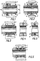
- the magnetron comprises an anode 1 ( Figure 1) and a cathode installed coaxially inside the anode and made in the form of a cylindrical hollow rod 2 with primary-emission and secondary-emission elements, arranged on its surface, their end faces adjoining each other.
- a primary-emission element is made in the form of at least one flat disk 3 provided with a central hole and made of a superfine foil of a refractory metal.
- the primary-emission element is made in the form of one flat disk 3 having the thickness ranging from fractions of micron to several microns and manufactured by stamping or electroerosion method.
- a secondary-emission element is made in the form of at least one cylindrical bush 4 manufactured from an emission-active material and installed coaxially with the disk 3 and rod 2.
- the secondary-emission element is made in the form of one cylindrical bush 4.
- Used as secondary-emission elements may be impregnated cathodes and also the cathodes based on metal alloys including platinum group metals, such as Pt, Ir, Os, Ru, Rh, Pd with admixtures of activators in the form of one or several elements of alkali-earth metals (Ba, Sr, Ca).
- Two focusing screens 5 are arranged on, and coaxially with the hollow cylindrical rod 2, which may be made of molybdenum or other refractory metal or their alloys.
- One focusing screen 5 is installed on the side of the cylindrical bush 4 and the other focusing screen 5 is located on the side of the flat disk 3.
- the external diameter of the disk 3 is greater than that of the cylindrical bush 4 by the value ranging from 0.1 to 0.2 the value of the interelectrode gap.
- Figure 1 also illustrates: h- the height of projection of the primary-emission element edge over the surface of the secondary-emission element; d - the external diameter of the secondary-emission element; D - the diameter of the anode 1.
- Values h in magnetrons of different designs usually constitute from 0.1 to 0.2 the value of the interelectrode cap which is equal to where D is the diameter of the magnetron anode and d - the external diameter of the secondary-emission element.
- the design of the magnetron working part illustrated in Figure 2 is similar to that illustrated in Figure 1, the only difference being that the magnetron shown in Figure 2 comprises two secondary-emission elements whose end faces adjoin the end faces of the disk 3. Besides, the focusing screens 5 are installed on the side of the other end faces of the secondary-emission elements.
- Illustrated in Figure 3 is the working part of the magnetron comprising five flat disks 3 and four cylindrical bushes 4 whose design is similar to that of the working part of the magnetron shown in Figure 1.
- the only difference consists in that one focusing screen 5 ( Figure 3) is installed on the side of the last disk 3.
- the primary-emission element can be made of several disks 3 depending on the type and design of the magnetron and also on the excitation current value.
- l (4 - 6) h (2), where h is the height of the projecting edge of the disk 3 whose value is found from the formula (1).
- the starting current can be reduced by no more than 10% its maximum value representing a sum of currents of separate disks 3 without consideration of their mutual screening.
- Shown in Figure 4 is a section of the magnetron working part demonstrating the end faces of the cylindrical bush 4 made in the form of a truncated cone whose smaller base adjoins the end face of the disk 3.
- the diameter of the cone greater base is an external diameter of the bush 4.
- Figure 5 illustrates a section of the magnetron working part whose design is similar to that of the section shown in Figure 4.
- the only difference consists in that the end faces of the adjacent flat disks 3 ( Figure 5) and bushes 4 adjoin each other through the flat cylindrical protective washer 6, each washer 6 being made of a thin foil of a refractory metal.
- the thickness of the washer 6 exceeds that of the disk 3 at least five to ten times.
- the washers 6 are made preferably of 15- to 30 ⁇ m thick tungsten.
- the design of the magnetron working part illustrated in Figure 6 is similar to that of the magnetron working part shown in Figure 1.
- the only difference consists in that the magnetron represented in Figure 6 comprises three disks 3, two bushes 4 and four washers 6.
- the screens 5 are installed on the side of the first and the last disks 3 and the washers 6 are installed between the adjacent disk 3 and bush 4.
- the washers 6 are installed with a purpose of protecting the disks 3 from possible deterioration as a result of chemical and physical interaction with the material of the bushes 4.
- the protective washer 6 made of tungsten can be installed.
- the present magnetron operates as follows.
- An anodic voltage is applied between the single-wire lead-in and the magnetron body (the lead-in and body are not shown in figures).
- the magnetron excitation current is ensured by the field emission from the primary-emission element edge directed towards the anode 1.
- the field emission is caused by the strong electric field created by the applied anodic voltage (the difference in potentials between the cathode and anode 1).
- the electrons emitted by said element accelerating and changing the direction of their movement under the action of the microwave electromagnetic field, get partially on the secondary-emission element and expell the secondary electrons which in their turn, multiplying in an avalanch-like manner, ensure the main operating currant of the magnetron.
- the present invention makes it possible to ensure an instantaneous starting of the magnetron with the first pulse without preliminary heating-up of the cathode owing to the provision of the electric field intensity required for obtaining the field emission sufficient in its value for excitation of the magnetron.
- the present invention can be used in radars, aircraft, sea ships, spacecraft, rockets, etc.
Landscapes
- Microwave Tubes (AREA)
- Manufacture And Refinement Of Metals (AREA)
Applications Claiming Priority (3)
| Application Number | Priority Date | Filing Date | Title |
|---|---|---|---|
| RU5043987 | 1992-04-15 | ||
| SU925043987A RU2007777C1 (ru) | 1992-04-15 | 1992-04-15 | Магнетрон |
| PCT/RU1992/000131 WO1993021648A1 (fr) | 1992-04-15 | 1992-06-26 | Magnetron |
Publications (3)
| Publication Number | Publication Date |
|---|---|
| EP0593768A1 true EP0593768A1 (de) | 1994-04-27 |
| EP0593768A4 EP0593768A4 (de) | 1994-12-28 |
| EP0593768B1 EP0593768B1 (de) | 1997-08-27 |
Family
ID=21605129
Family Applications (1)
| Application Number | Title | Priority Date | Filing Date |
|---|---|---|---|
| EP92915517A Expired - Lifetime EP0593768B1 (de) | 1992-04-15 | 1992-06-26 | Magnetron |
Country Status (7)
| Country | Link |
|---|---|
| EP (1) | EP0593768B1 (de) |
| JP (1) | JP2740793B2 (de) |
| KR (1) | KR100216657B1 (de) |
| DE (1) | DE69221873T2 (de) |
| RU (1) | RU2007777C1 (de) |
| UA (1) | UA7649C2 (de) |
| WO (1) | WO1993021648A1 (de) |
Cited By (7)
| Publication number | Priority date | Publication date | Assignee | Title |
|---|---|---|---|---|
| FR2699325A1 (fr) * | 1992-12-11 | 1994-06-17 | Litton Systems Inc | Suppression de l'instabilité dans un amplificateur à champs croisés à l'aide d'un émetteur de champ. |
| EP0694948A3 (de) * | 1994-06-28 | 1996-04-03 | Sharp Kk | Magnetron und Mikrowellenofen |
| US5874806A (en) * | 1996-10-02 | 1999-02-23 | Litton Systems, Inc. | Passive jitter reduction in crossed-field amplifier with secondary emission material on anode vanes |
| US6329753B1 (en) | 1998-01-08 | 2001-12-11 | Litton Systems, Inc. | M-type microwave device with slanted field emitter |
| US6388379B1 (en) | 1998-01-08 | 2002-05-14 | Northrop Grumman Corporation | Magnetron having a secondary electron emitter isolated from an end shield |
| EP1505627A3 (de) * | 2003-08-07 | 2008-03-05 | Matsushita Electric Industrial Co., Ltd. | Magnetron |
| CN107045970A (zh) * | 2017-03-24 | 2017-08-15 | 西南交通大学 | 二次电子倍增阴极电子枪 |
Families Citing this family (4)
| Publication number | Priority date | Publication date | Assignee | Title |
|---|---|---|---|---|
| RU2115193C1 (ru) * | 1994-03-22 | 1998-07-10 | Владимир Ильич Махов | Магнетрон |
| JP2003272537A (ja) * | 2002-03-20 | 2003-09-26 | Matsushita Electric Ind Co Ltd | マグネトロン |
| RU2494489C1 (ru) * | 2012-02-10 | 2013-09-27 | Общество с ограниченной ответственностью "Плутон Инвест" | Магнетрон с безнакальным запуском со специальным активированием автоэлектронных катодов |
| CN109065427A (zh) * | 2018-06-29 | 2018-12-21 | 安徽华东光电技术研究所有限公司 | 一种冷阴极磁控管的阴极 |
Family Cites Families (7)
| Publication number | Priority date | Publication date | Assignee | Title |
|---|---|---|---|---|
| FR1306999A (fr) * | 1961-11-25 | 1962-10-19 | Cie Francaise De Micro Ondes | Cathode froide pour magnétron |
| BE625855A (de) * | 1962-03-15 | |||
| GB1023598A (en) * | 1964-05-11 | 1966-03-23 | English Electric Valve Co Ltd | Improvements in or relating to magnetron cathodes |
| US3297901A (en) * | 1964-06-05 | 1967-01-10 | Litton Industries Inc | Dispenser cathode for use in high power magnetron devices |
| GB2029632B (en) * | 1978-09-02 | 1982-08-11 | English Electric Valve Co Ltd | Magnetrons |
| JPS5978427A (ja) * | 1982-10-28 | 1984-05-07 | Toshiba Corp | マグネトロン |
| US4480235A (en) * | 1983-01-18 | 1984-10-30 | Varian Associates, Inc. | Coaxial magnetron with improved starting |
-
1992
- 1992-04-15 RU SU925043987A patent/RU2007777C1/ru active
- 1992-06-26 KR KR1019930703900A patent/KR100216657B1/ko not_active Expired - Fee Related
- 1992-06-26 JP JP5518211A patent/JP2740793B2/ja not_active Expired - Fee Related
- 1992-06-26 EP EP92915517A patent/EP0593768B1/de not_active Expired - Lifetime
- 1992-06-26 DE DE69221873T patent/DE69221873T2/de not_active Expired - Fee Related
- 1992-06-26 UA UA93002425A patent/UA7649C2/uk unknown
- 1992-06-26 WO PCT/RU1992/000131 patent/WO1993021648A1/ru not_active Ceased
Cited By (10)
| Publication number | Priority date | Publication date | Assignee | Title |
|---|---|---|---|---|
| FR2699325A1 (fr) * | 1992-12-11 | 1994-06-17 | Litton Systems Inc | Suppression de l'instabilité dans un amplificateur à champs croisés à l'aide d'un émetteur de champ. |
| EP0694948A3 (de) * | 1994-06-28 | 1996-04-03 | Sharp Kk | Magnetron und Mikrowellenofen |
| US5676873A (en) * | 1994-06-28 | 1997-10-14 | Sharp Kabushiki Kaisha | Microwave oven and magnetron with cold cathode |
| US5874806A (en) * | 1996-10-02 | 1999-02-23 | Litton Systems, Inc. | Passive jitter reduction in crossed-field amplifier with secondary emission material on anode vanes |
| US6329753B1 (en) | 1998-01-08 | 2001-12-11 | Litton Systems, Inc. | M-type microwave device with slanted field emitter |
| US6388379B1 (en) | 1998-01-08 | 2002-05-14 | Northrop Grumman Corporation | Magnetron having a secondary electron emitter isolated from an end shield |
| EP1505627A3 (de) * | 2003-08-07 | 2008-03-05 | Matsushita Electric Industrial Co., Ltd. | Magnetron |
| US7474042B2 (en) | 2003-08-07 | 2009-01-06 | Matsushita Electric Industrial Co., Ltd. | Magnetron with graphite nano-fibers on cathode |
| CN107045970A (zh) * | 2017-03-24 | 2017-08-15 | 西南交通大学 | 二次电子倍增阴极电子枪 |
| CN107045970B (zh) * | 2017-03-24 | 2019-02-26 | 西南交通大学 | 二次电子倍增阴极电子枪 |
Also Published As
| Publication number | Publication date |
|---|---|
| UA7649C2 (uk) | 1995-12-26 |
| KR100216657B1 (ko) | 1999-09-01 |
| JP2740793B2 (ja) | 1998-04-15 |
| EP0593768A4 (de) | 1994-12-28 |
| DE69221873T2 (de) | 1998-01-29 |
| KR940701581A (ko) | 1994-05-28 |
| EP0593768B1 (de) | 1997-08-27 |
| WO1993021648A1 (fr) | 1993-10-28 |
| DE69221873D1 (de) | 1997-10-02 |
| RU2007777C1 (ru) | 1994-02-15 |
| JPH06510629A (ja) | 1994-11-24 |
Similar Documents
| Publication | Publication Date | Title |
|---|---|---|
| EP0593768B1 (de) | Magnetron | |
| US5019752A (en) | Plasma switch with chrome, perturbated cold cathode | |
| EP0185074B1 (de) | Elektronenstrahlgesteuerter schalter von radialer gestaltung, der eine draht-ionenplasma-elektronenquelle verwendetund eine derartige electronenquelle | |
| US4737680A (en) | Gridded electron gun | |
| US2411601A (en) | Electronic discharge device | |
| US4380717A (en) | Magnetrons | |
| US4757524A (en) | X-ray generator | |
| US3903450A (en) | Dual-perveance gridded electron gun | |
| US6329753B1 (en) | M-type microwave device with slanted field emitter | |
| US6388379B1 (en) | Magnetron having a secondary electron emitter isolated from an end shield | |
| RU2051439C1 (ru) | Магнетрон | |
| RU2115193C1 (ru) | Магнетрон | |
| US4839554A (en) | Apparatus for forming an electron beam sheet | |
| US2412842A (en) | Electronic discharge cathode | |
| JP3427676B2 (ja) | 面放電型プラズマ・ディスプレイ・パネルおよびその放電維持電極の形成方法 | |
| US20030042841A1 (en) | Vacuum fluorescent display with rib grid | |
| US4891731A (en) | Gas discharge over-voltage arrestor having a line of ignition | |
| RU2760980C1 (ru) | Взрывоэмиссионный катод электронной пушки | |
| RU2538780C1 (ru) | Магнетрон с запускающими автоэлектронными эмиттерами на концевых экранах катодных узлов | |
| US2249604A (en) | Controllable electric discharge device | |
| JP2919156B2 (ja) | 放電ランプ用陰極 | |
| GB2407205A (en) | A Hop-FED structure | |
| GB2238903A (en) | Magnetron cathode | |
| JPH0896698A (ja) | 電子放出素子 | |
| JPS61140026A (ja) | 螢光表示管 |
Legal Events
| Date | Code | Title | Description |
|---|---|---|---|
| PUAI | Public reference made under article 153(3) epc to a published international application that has entered the european phase |
Free format text: ORIGINAL CODE: 0009012 |
|
| AK | Designated contracting states |
Kind code of ref document: A1 Designated state(s): DE FR GB IT |
|
| 17P | Request for examination filed |
Effective date: 19940421 |
|
| A4 | Supplementary search report drawn up and despatched | ||
| AK | Designated contracting states |
Kind code of ref document: A4 Designated state(s): DE FR GB IT |
|
| GRAG | Despatch of communication of intention to grant |
Free format text: ORIGINAL CODE: EPIDOS AGRA |
|
| 17Q | First examination report despatched |
Effective date: 19960325 |
|
| GRAH | Despatch of communication of intention to grant a patent |
Free format text: ORIGINAL CODE: EPIDOS IGRA |
|
| GRAH | Despatch of communication of intention to grant a patent |
Free format text: ORIGINAL CODE: EPIDOS IGRA |
|
| GRAA | (expected) grant |
Free format text: ORIGINAL CODE: 0009210 |
|
| AK | Designated contracting states |
Kind code of ref document: B1 Designated state(s): DE FR GB IT |
|
| ITF | It: translation for a ep patent filed | ||
| REF | Corresponds to: |
Ref document number: 69221873 Country of ref document: DE Date of ref document: 19971002 |
|
| ET | Fr: translation filed | ||
| PLBE | No opposition filed within time limit |
Free format text: ORIGINAL CODE: 0009261 |
|
| STAA | Information on the status of an ep patent application or granted ep patent |
Free format text: STATUS: NO OPPOSITION FILED WITHIN TIME LIMIT |
|
| 26N | No opposition filed | ||
| REG | Reference to a national code |
Ref country code: GB Ref legal event code: IF02 |
|
| PGFP | Annual fee paid to national office [announced via postgrant information from national office to epo] |
Ref country code: FR Payment date: 20020610 Year of fee payment: 11 |
|
| PGFP | Annual fee paid to national office [announced via postgrant information from national office to epo] |
Ref country code: GB Payment date: 20020626 Year of fee payment: 11 |
|
| PGFP | Annual fee paid to national office [announced via postgrant information from national office to epo] |
Ref country code: DE Payment date: 20020702 Year of fee payment: 11 |
|
| PG25 | Lapsed in a contracting state [announced via postgrant information from national office to epo] |
Ref country code: GB Free format text: LAPSE BECAUSE OF NON-PAYMENT OF DUE FEES Effective date: 20030626 |
|
| PG25 | Lapsed in a contracting state [announced via postgrant information from national office to epo] |
Ref country code: DE Free format text: LAPSE BECAUSE OF NON-PAYMENT OF DUE FEES Effective date: 20040101 |
|
| GBPC | Gb: european patent ceased through non-payment of renewal fee |
Effective date: 20030626 |
|
| PG25 | Lapsed in a contracting state [announced via postgrant information from national office to epo] |
Ref country code: FR Free format text: LAPSE BECAUSE OF NON-PAYMENT OF DUE FEES Effective date: 20040227 |
|
| REG | Reference to a national code |
Ref country code: FR Ref legal event code: ST |
|
| PG25 | Lapsed in a contracting state [announced via postgrant information from national office to epo] |
Ref country code: IT Free format text: LAPSE BECAUSE OF NON-PAYMENT OF DUE FEES;WARNING: LAPSES OF ITALIAN PATENTS WITH EFFECTIVE DATE BEFORE 2007 MAY HAVE OCCURRED AT ANY TIME BEFORE 2007. THE CORRECT EFFECTIVE DATE MAY BE DIFFERENT FROM THE ONE RECORDED. Effective date: 20050626 |