EP0593787B1 - Mechanisme d'entrainement pour appareil transporteur accouple - Google Patents
Mechanisme d'entrainement pour appareil transporteur accouple Download PDFInfo
- Publication number
- EP0593787B1 EP0593787B1 EP93911963A EP93911963A EP0593787B1 EP 0593787 B1 EP0593787 B1 EP 0593787B1 EP 93911963 A EP93911963 A EP 93911963A EP 93911963 A EP93911963 A EP 93911963A EP 0593787 B1 EP0593787 B1 EP 0593787B1
- Authority
- EP
- European Patent Office
- Prior art keywords
- chain
- drive
- endless
- extended portion
- travelling
- Prior art date
- Legal status (The legal status is an assumption and is not a legal conclusion. Google has not performed a legal analysis and makes no representation as to the accuracy of the status listed.)
- Expired - Lifetime
Links
- 230000001174 ascending effect Effects 0.000 claims abstract description 14
- 230000005540 biological transmission Effects 0.000 claims description 10
- 230000001154 acute effect Effects 0.000 claims description 4
- 238000000034 method Methods 0.000 description 2
- 230000002093 peripheral effect Effects 0.000 description 2
- 241001669679 Eleotris Species 0.000 description 1
- 238000010276 construction Methods 0.000 description 1
- 238000009434 installation Methods 0.000 description 1
- 230000004048 modification Effects 0.000 description 1
- 238000012986 modification Methods 0.000 description 1
Images




Classifications
-
- B—PERFORMING OPERATIONS; TRANSPORTING
- B66—HOISTING; LIFTING; HAULING
- B66B—ELEVATORS; ESCALATORS OR MOVING WALKWAYS
- B66B23/00—Component parts of escalators or moving walkways
- B66B23/02—Driving gear
-
- B—PERFORMING OPERATIONS; TRANSPORTING
- B66—HOISTING; LIFTING; HAULING
- B66B—ELEVATORS; ESCALATORS OR MOVING WALKWAYS
- B66B21/00—Kinds or types of escalators or moving walkways
- B66B21/02—Escalators
- B66B21/08—Escalators paternoster type, i.e. the escalator being used simultaneously for climbing and descending
Definitions
- the present invention relates to a drive mechanism of an endless track conveyor apparatus comprising individual treads connected integrally one to another so that all the treads are kept level, more particularly to a drive mechanism preferably applied to an escalator or a moving sidewalk.
- An object of the present invention is to provide a driving mechanism for an endless track conveyor apparatus which is capable of saving driving power by utilising the weight of a descending stairway without increasing step height, without accumulating loads on the treads, and without requiring high accuracy in the drive of the treads.
- an endless track conveyor comprising: a guide mechanism for guiding a conveyor frame of the endless track conveyor apparatus along an endless travelling track, said endless travelling track including an ascending section, a descending section, and horizontal straight sections and U-turn sections connecting said ascending and descending sections; and a drive chain for said conveyor frame, provided along said endless travelling track; characterised by: a first drive chain being provided along said ascending section of the endless travelling track, and a second drive chain being provided along said descending section of the endless travelling track; a drive mechanism for rotating said first drive chain in a predetermined direction; a driven device comprising a plurality of slats superposed one alongside another, each of said slats being swingably or linearly reciprocally installed on said conveyor frame and being engageable with teeth provided on either of upper and lower portions of a chain link of said first drive chain, said conveyor frame receiving a driving force from said first drive chain through said driven device so that, in use, the conveyor frame is located above a surface defined by said
- the reversal transmission mechanism is provided along said descending section of said endless travelling track, said second drive chain has chain links provided with teeth engageable with said slats installed on said conveyor frame, and said reversal transmission mechanism comprises a chain sprocket driven by said second drive chain, a rotational axis of said chain sprocket, and a power transmission mechanism transmitting rotational force of said rotational axis to said first drive chain.
- an endless track conveyor apparatus which circulates a number of integrally connected step bodies on rails while maintaining their treads horizontal, comprising: a step body including a frame portion having a tread thereon, right and left bracket portions, said bracket portions including a wheel travelling on a rail, and a connecting link rotatably connecting two adjacent step bodies; and a drive chain travelling in parallel with a longitudinal direction of said connecting link, characterised by: said step body having a slat holder disposed parallel to said connecting link; said drive chain travelling in parallel with a longitudinal direction of said slat holder and having right and left chain links extending in the chain travelling direction to define chain link extended portions; said chain link extended portions of the right and left chain links having inner surfaces forming teeth consisting of ridges and bottoms, said ridges and bottoms of one chain link extended portion confronting with bottoms and ridges of the other chain link extended portion respectively; said slat holder holding a driven device consisting of a plurality of hard
- said teeth formed on said one chain link extended portion and said teeth formed on said the other chain link extended portion are respectively formed to have equal pitch, with the tooth trace of these teeth being normal to the travelling direction of the chain, the tooth trace of said one chain link extended portion and the tooth trace of said the other chain link extended portion forming an acute angle therebetween in such a manner that a distance between these tooth traces increases as it goes to remote ends of the teeth;
- said hard slats supported on the slat holder are swingable, within a limited angle, about a slat spindle provided on a boss of the slat holder, and each of said hard slats has a head formed in a shape corresponding to said acute angle formed between the tooth trace of one chain link extended portion and the opposing tooth trace of the other chain link extended portion; and the teeth of said drive chain transmit driving force through said hard slats to said slat spindle and said slat holder boss supporting said slat spindle, thereby transmitting
- each of said right and left bracket portions prefferably include a support portion supporting said frame portion and an upper extended portion supporting said connecting link, said support portion and said upper extended portion being spaced by a groove into which a skirt guard panel is inserted, whereby the drive chain is disposed outside said skirt guard panel and concealed below a moving handrail.
- An escalator shown in the following description as one example of an endless track conveyor apparatus, includes a going by ascending track and a returning by descending track, which are disposed in parallel and connected with each other.
- This escalator includes, as main components, a parallel link mechanism using connecting links foldable at the center, a mechanism for keeping the treads level by the use of a free rotation disk provided at U-turn track sections, and a roller chain.
- the drive mechanism of this escalator includes hard slats by which weight of the descending travelling track is utilized for saving driving power.
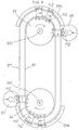
- a circulating endless track A, B, C,---, L, M, N, and A shows an inner rail of the travelling track of the escalator.
- a portion A-B is referred to as a downstairs first straight travelling section
- a portion B-C is referred to as a shift-to-upward travelling section
- a portion C-D is referred to as an inclined straight ascending section
- a portion D-E is referred to as an upstairs shift-to-horizontally straight travelling section
- a portion E-F is referred to as an upstairs first straight travelling section
- a portion F-G-H is referred to as an upstairs horizontal U-turn section
- a portion H-I is referred to as an upstairs second straight travelling section
- a portion I-J is referred to as a shift-to-downward travelling section
- a portion J-K is referred to as an inclined straight descending section
- a portion K-L is referred to as a downstairs shift-to-horizontally straight travelling section
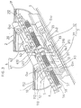
- Fig. 3 is a side view schematically showing a drive mechanism for driving treads of the inner stairway of the escalator in a straight ascending section C-D.
- Any adjacent two steps 1 and 2 are connected with each other by means of a parallel link mechanism which ties the pin connecting points O 31 , O 41 ; and O 32 , O 42 disposed on perpendiculars passing through the centers of their treads 10 and 20, respectively.
- a connecting link 3 for the pin connecting points O 31 and O 32 of the steps 1 and 2.
- a connecting link 4 for the pin connecting points O 41 and O 42 of the steps 1 and 2.
- the connecting link 3 consists of a pair of half links 31 and 32 connected with each other at the center rotatably about a pin 33
- the connecting link 4 consists of a pair of half links 41 and 42 connected with each other at the center rotatably about a pin 43. Accordingly, these connecting links 3 and 4 are foldable at the U-turn sections F-G-H and M-N-A of the travelling track about the pins 33 and 34 whose axes extend in the up-and-down direction.
- the steps 1 and 2 have V-shaped grooves 112 and 212 respectively extending horizontally along the inner side thereof. These V-shaped grooves 112 and 212 mesh with peripheral edges of disks 03 and 04 disposed rotatably around vertical axes 031 and 041 at the upstairs and downstairs U-turn sections (i.e. portions F-G-H and M-N-A in Fig. 1), respectively, as shown in a plane view of Fig. 8. This arrangement ensures the treads 10 and 20 to stabilize the position horizontally at the U-turn sections.
- the step 1 basically consists of three main components of a frame portion 11 having a tread 10 on the upper surface thereof, a right bracket portion 12, and a left bracket portion 12'. These components are manufactured separately.
- the right and left bracket portions 12 and 12' are connected first of all through the spindle 15.
- the frame portion 11 is fixed on these right and left bracket portions 12 and 12' by means of bolts 14, 14'.
- the right and left bracket portions 12 and 12' are symmetrical and identical in size; therefore, they are suitable to mass production. It is, however, possible to form an integral structure of the above three components.
- a wheel 13 and a slat holder 5 are provided at the lower part of the bracket portion 12 and rotatably coupled with the extended portion of the spindle 15 in such a manner that the axes of these wheel 13 and the slat holder 5 coincide with the axis X1 of the spindle 15.
- the slat holder 5 is always held in parallel with the lower half link 31 since it is connected with the parallel link mechanism previously described.
- a roller chain 6 travels above and in parallel with the slat holder 5. As described later, the roller chain 6 has right and left link plates having teeth thereon. Hard slats 50 accommodated in the slat holder 5 mesh with these teeth.
- the chain 6 used in this embodiment is characterized in that no bush is used and a needle-type roller bearing is provided between a pin and a link.
- a pin 60 has a central portion to be coupled with a roller 61 and first and second stepped portions extending successively from the central portion toward remote end in both the right and left directions. Adjacent two (first and second) pins 60 and 60, disposed in parallel with each other, are connected by means of a pair of first connecting chain links 62a and 62b which couple with approximately inner 1/3 of the right and left first stepped portions.
- second and third pins 60 and 60 are not connected by means of the first connecting chain links 62a and 62b. Instead, these second and third pins 60 and 60 are foldably connected with each other by means of a pair of movable links 64a and 64b which couple with the remaining 2/3 of the right and left first stepped portions through the needle-type rollers 63a and 63b.
- the above two adjacent pins 60, 60 connected by the first connecting chain links 62a and 62b are further connected by a pair of second connecting chain link 65a and 65b coupled at the second stepped portions.
- the second stepped portions have holes 66a and 66b for receiving cotter pins 67a and 67b by which the second connecting chain links 65a and 65b are prevented from falling off the pin 60.
- first connecting chain links 62a and 62b have lower extended portions 162a and 162b integrally formed so as to extend in the chain travelling direction by a length twice as long as the chain pitch. As shown in Fig. 6, these extended portions 162a and 162b of the first connecting chain links 62a and 62b contact with adjacent extended portions 162a and 162b of another first connecting chain links 62a and 62b since these extended portions 162a and 162b have length twice as long as the chain pitch in the chain travelling direction.
- the extended portions 162a and 162b of the first connecting chain links 62a and 62b confront with each other in such a manner that a distance between extended portions 162a and 162b increases gradually as it goes downward (toward the axis of the spindle 15) as shown in Fig. 5.
- These extended portions 162a and 162b have inside surfaces which are formed with low teeth, each tooth trace extending in a direction normal to the chain travelling direction.
- the teeth of the extended portion 162a and the teeth of the extended portion 162b are formed in a manner such that a toothtrace in the portion 162a and a tooth trace in the portion 162b intersect with each other by approximately 20 degrees or less and further a tooth ridge in the portion 162a and a tooth bottom in the portion 162b are opposed each other.
- the extended portion 162a of the first connecting chain link 62a is identical with the extended portion 162b of the second connecting chain link 62b in configuration of the teeth.
- the first connecting chain link 62a can be used, if reversed, as the second connecting chain link 62b, the ridges of the teeth of one extended portion accurately confronting with the bottoms of the opposite teeth of the other extended portion. Furthermore, instead of using cotter pins 67a and 67b, caulking the ends of the spindle 15 as shown in Figs. 6 and 7 would be effective for preventing the link from falling off.
- Hard slats 50 mesh with the teeth formed on the extended portions 162a of the first connecting chain link 62b and the opposite extended portion 162b of the second connecting chain link 62b.
- Each of the hard slats 50 has a hole opened at a base end thereof.
- a slat spindle 52 fixed to the boss 51 of the slat holder 5, passes through the hole of each hard slat 50.
- the combination of hard slats 50 constitutes teeth which are capable of changing in their general shape.
- the boss 51 of the slat holder 5 has a pair of stopper bars 53 and 54 provided thereon as shown in Fig. 5.
- stopper bars 53 and 54 restrict the swing angle of each slat 50 within 2 ⁇ in the right to left direction.
- Driving force, transmitted from the chain 6 to the slats 50, is received by end plates 55, 56 fixed to the both ends of the slat spindle 52 and the boss 51 (Refer to Fig. 7).
- a chain sprocket may be used for pushing the chain 6 against the hard slats 50 in order to prevent the chain 6 from floating and ensure the meshing engagement between the slats 50 and the chain 6.
- the hard slats 50 of swing type as described above can be replaced by ones of reciprocating linear motion type.
- a body of a step 1 includes a frame portion 11 equipped with a tread 10 and a riser 110 (Fig. 3), a bracket portion 12 at the inner rail side equipped with the connecting links 3, 4, the slat holder 5, and the wheel 13, and a bracket portion 12' at the outer rail side equipped with the connecting links 3', 4', the slat holder 5', and the wheel 13'. These three components are connected by means of the bolts 14 and 14'.
- the bracket portion 12 of the step 1 consists of a support portion 121 supporting the frame portion 11, a bearing portion 122 supporting an extended portion 152 of an axle 151, a lower extended portion 123 supporting the connecting link 3, and an upper extended portion 124 supporting the connecting link 4.
- the axle 151 and its extended portion 152 are coaxial with the spindle 15 as well as an axle 151' at the outer rail side and its extended portion 152'; therefore, these members have a common axis X1 extending horizontally.
- This horizontal axis X1 is located at a position equally spaced from an axis 30 of the connecting link 3 and an axis 40 of the connecting link 4.
- a groove portion 125 is formed between the support portion 121 supporting the frame portion 11 and the upper extended portion 124 supporting the connecting link 4.
- a skirt guard panel 05 is inserted in this groove portion 125. Therefore, the driving chain 6 is positioned outside this skirt panel 05. Namely, the driving chain 6 is disposed in a space below a moving handrail (not shown).
- the spindle 15 has a pair of flanges 150 and 150' at right and left portions thereof for positioning of the wheels 13 and 13'.
- the extended axles 152 and 152' are further extended at remote ends thereof for forming end axles 153 and 153', on which the bosses 51 and 51' of the slat holders 5 and 5' are fixed (Figs 3 and 5).
- the slat spindle 52 and stopper bars 53, 54 pass through the boss 51 of the slat holder.
- These slat spindle 52 and stopper bars 53, 54 pierce the boss 51 of the slat holder and have cutouts formed at the centers of their longitudinal directions so as to get astride the end axle 153.
- the half links 311 and 411 are rotatably connected with a vertical link 341 through pins 310 and 410, respectively. Furthermore this vertical link 341 is rotatably connected, at its center, with the end plate 55 of the slat holder by means of a pin 340.
- the half link 31 and the vertical link 341 cooperatively constitute a parallel link mechanism, which always maintains the slat holder 5 parallel to the half link 31.
- each of the components at the outer rail is side given the same reference numeral as the corresponding component at the inner rail side although "'" is added at the end of the numeral because the components at the inner rail side and the components at the outer rail side have good correspondence.
- the connecting links 3' and 4' at the outer rail side are differentiated a little bit from the connecting links 3 and 4 at the inner rail side in their structures. More specifically, the half links 31' and 32' of the connecting link 3' and the half links 41' and 42' of the connecting link 4' are constituted to be separable.
- the half link ends 311' and 411' are rotatably connected with each other via a vertical link 341' and pins 310', 410' as shown in Fig. 4. And, the center of this vertical link 341' is rotatably connected to the end plate 55' of the slat holder 5' through a pin 340'. Furthermore, an auxiliary wheel 312' coaxial with the pin 310' is guided by an auxiliary rail 06' which is parallel to the outer rail 01'.
- the remaining half links 32' and 42' of the connecting links 3' and 4' at the outer rail side are rotatably connected with each other via a vertical link 342' and pins 320', 420' in the same manner as in the case of the half links 31' and 41'.
- the slat holder 5' is not connected with this vertical link 342'.
- the pin 320' is attached with a coaxial auxiliary wheel 322' which is guided by an auxiliary rail 06', in the same manner as in the case of the pin 310'.
- frictional wheels 07 and 08 are respectively provided outside the connecting points of the U-turn sections and the straight sections, so that the step 2 is securely connected at the outer rail side after transferring from the U-turn section to the straight section of the travelling track.
- the frictional wheels 07 and 08 enter a V-shaped groove 112' (Fig. 2) provided on the outside edge of the frame portion 11.
- the rotational speed of these frictional wheels 07 and 08 are set slightly faster than the travelling speed of the step 2. This speed difference causes frictional force which accelerates the step 2 and, therefore, the half links 31' and 32' and the half links 41' and 42' are engaged firmly.
- a mechanism shown in Fig. 1 is suitable for driving the chain 6 which drives the steps.
- a motor 100 drives an axis 102 via a speed reduction device 101.
- a chain sprocket 103 provided on the axis 102, transmits driving force to a chain sprocket 104 via a chain.
- An axis 105 provided coaxially with the chain sprocket 104, is thus driven.
- a chain sprocket 70 on the axis 105 drives a chain sprocket 71 which is coaxial with a chain sprocket 72 for driving the chain 6.
- a chain sprocket 70' on the axis 105 drives a chain sprocket 71' coaxial with a chain sprocket 72' for driving the chain 6'.
- the chain 8 is given tension by the weight of a stairway and passengers and therefore a chain sprocket 92 is rotated. Such rotation of the chain sprocket 92 is transmitted to a chain sprocket 90 coaxial with the chain sprocket 92.
- a gear 107 provided on an axis 108 of the chain sprocket 90, transmits rotation to a gear 106 on the axis 105 which has same number of tooth as that of the gear 107.
- rotational force is transmitted via a path passing through the chain 8' ⁇ the chain sprockets 92' ⁇ 91' ⁇ 90' ⁇ the axis 108. Accordingly, the weight of the descending stairway contributes to the saving of drive power.
- the present invention in accordance with the drive mechanism for the conveyor apparatus of the present invention, it becomes possible to save the drive power with utilization of weight of the descending stairway without accumulating loads on the treads and without requiring high accuracy in the drive of individual treads. Furthermore, increase of the height of the steps can be adequately suppressed. Moreover, as a means for transmitting driving force of the chain to the steps, the present invention utilizes a driven medium comprising a number of piled-up slats (hard slats) capable of swinging in the direction normal to the chain travelling direction. Thus, no phase adjustment is necessary and high accuracy is not required.
- a sleeper or cross tie 09 will be fixed on the stairs and then the rails 01 and 01' will be fixed thereon as shown in Fig. 4.
- This invention can be applied to a moving sidewalk in the same manner. Compared with the conventional one, it becomes possible to install the moving sidewalk by digging a shallow groove. Going and returning travelling tracks can be assembled as one set.
- the track conveyor according to this invention would function as an escalator when applied to a rugged path, thus ensuring simple installation.
Landscapes
- Chain Conveyers (AREA)
- Escalators And Moving Walkways (AREA)
- Discharge By Other Means (AREA)
Claims (5)
- Un appareil transporteur à piste sans fin comprenant :un mécanisme de guidage pour guider un bâti transporteur (1) de l'appareil transporteur à piste sans fin le long d'une piste à déplacement sans fin (A-N), ladite piste à déplacement sans fin comprenant une partie ascendante (C-D), une partie descendante (J-K), et des parties horizontales rectilignes (E-F, H-I, L-M, A-B) ainsi que des parties de retournement (F-G-H-M-N-A) reliant lesdites parties ascendante et descendante (C-D, J-K); etune chaíne d'entraínement pour ledit bâti transporteur, prévue le long de la piste à déplacement sans fin;
caractérisé par :une première chaíne d'entraínement (6) prévue le long de ladite partie ascendante (C-D) de la piste à déplacement sans fin, et une seconde chaíne d'entraínement (8) prévue le long de ladite partie descendante(J-K) de la piste à déplacement sans fin;un mécanisme d'entraínement (100-104) pour faire tourner ladite première chaíne d'entraínement (6) dans une direction prédéterminée;un dispositif entraíné (5) comprenant un ensemble de plaquettes (5) superposées les unes le long des autres, chacune desdites plaquettes (50) étant montée de manière pivotante ou linéairement en va-et-vient sur ledit bâti transporteur (1) et pouvant s'engager avec des dents prévues sur l'une quelconque des parties supérieure et inférieure d'un maillon (62a, 62b) de ladite première chaíne d'entraínement (6), ledit bâti transporteur (1) recevant une force d'entraínement provenant de ladite première chaíne d'entraínement (6) par l'intermédiaire dudit dispositif entraíné (5) de sorte que, en service, le bâti transporteur soit placé au-dessus d'une surface définie par ladite piste à déplacement sans fin (A-N) et circule le long de ladite piste à déplacement sans fin (A-N); etun mécanisme de transmission à inversion (105-108) pour convertir une charge agissant sur ladite seconde chaíne d'entraínement (8) au niveau de ladite partie descendante (J-K) de ladite piste à déplacement sans fin (A-N) en un mouvement de rotation, puis inversant cette force de rotation pour la transmettre audit mécanisme d'entraínement (100-104) pour ladite première chaíne d'entraínement (6). - Un appareil transporteur à piste sans fin selon la revendication 1, dans lequel ledit mécanisme de transmission à inversion (105-108) est prévu le long de ladite partie descendante (J-K) de ladite piste à déplacement sans fin, ladite seconde chaíne d'entraínement (8) présente des maillons munis de dents pouvant s'engager avec lesdites plaquettes (50) montées sur ledit bâti transporteur, et ledit mécanisme de transmission à inversion (105-108) comprend une roue à chaíne entraínée par ladite seconde chaíne d'entraínement (8), un axe de rotation (108) de ladite roue à chaíne, et un mécanisme de transmission de puissance transmettant la force de rotation dudit axe de rotation (108) à ladite première chaíne d'entraínement (6).
- Un appareil transporteur à piste sans fin qui fait circuler un certain nombre de marches reliées ensemble (1, 2) sur des rails tout en maintenant horizontaux leurs plans de marche (10), comprenant :une marche (1) présentant une partie de bâti (11) avec un plan de marche (10) dessus, des parties de support de droite et de gauche (12, 12'), lesdites parties de support (12, 12') comprenant une roue (13, 13') se déplaçant sur un rail, et une liaison intermédiaire (31) reliant en rotation deux marches adjacentes (1, 2) ; etune chaíne d'entraínement (6) se déplaçant parallèlement à une direction longitudinale de ladite liaison intermédiaire (31),
caractérisé par le fait que :ladite marche (1) présente un support de plaquettes (5) disposé parallèlement à ladite liaison intermédiaire (31) ;ladite chaíne d'entraínement (6) se déplace parallèlement à la direction longitudinale dudit support de plaquettes (5) et présente des maillons de droite et de gauche (62a, 62b) s'étendant dans la direction de déplacement de la chaíne pour définir des parties de prolongement de maillon (162a, 162b) ;lesdites parties de prolongement de maillon (162a, 162b) des maillons de droite et de gauche (62a, 62b) présentent des surfaces internes formant des dents comprenant des arêtes et des fonds, lesdites arêtes et lesdits fonds d'une première partie de prolongement de maillon (162a) venant respectivement en face des fonds et des arêtes de l'autre partie de prolongement de maillon (162b) ;ledit support de plaquettes (5) maintient un dispositif entraíné se composant d'un ensemble de plaquettes dures (50) superposées les unes le long des autres et pouvant pivoter ou avancer linéairement en va-et-vient approximativement dans une direction axiale d'une broche (60) de ladite chaíne (6) pour coopérer avec lesdites dents, chacune des plaquettes dures (50) étant poussée par une arête d'une dent formée sur une première partie de prolongement de maillon (162a) et entrant dans un fond de la dent opposée formée sur l'autre partie de prolongement de maillon (162b) lorsqu'elle traverse un espace interne entre lesdites parties de prolongement de maillon de droite et de gauche (162a, 162b); etladite chaíne d'entraínement (6) est entraínée par un système d'entraínement à roue à chaíne (100-104) présentant un axe d'entraínement (102) entraíné dans une direction prédéterminée et par un mécanisme de transmission à inversion (105-108) se composant d'un autre système d'entraínement à roue à chaíne présentant un autre axe d'entraínement (108) entraíné dans une direction opposée audit axe d'entraínement (102). - Un appareil transporteur à piste sans fin selon la revendication 3, dans lequel :lesdites dents formées sur ladite première partie de prolongement de maillon (162a) et lesdites dents formées sur ladite autre partie de prolongement de maillon (162b) sont respectivement formées pour présenter un pas égal, les traces des dents de ces dents étant normales à la direction de déplacement de la chaíne (6), la trace des dents de ladite première partie de prolongement de maillon (162a) et la trace des dents de ladite autre partie de prolongement de maillon (162b) formant un angle aigu entre elles de telle manière qu'une distance entre ces traces de dents augmente au fur et à mesure qu'elle va vers les extrémités éloignées de la dent;lesdites plaquettes dures (50) portées par le support de plaquettes (5) peuvent pivoter, à l'intérieur d'un angle limité, autour d'un arbre de plaquettes (52) présentant un bossage (51) du support de plaquettes (5), et chacune des plaquettes dures (50) présente une tête ayant une forme correspondant audit angle aigu formé entre la trace des dents d'une partie de prolongement de maillon (162a) et la trace des dents opposées de l'autre partie de prolongement de maillon (162b); etles dents de ladite chaíne d'entraínement (6) transmettent la force d'entraínement par l'intermédiaire desdites plaquettes dures (50) audit arbre (52) de plaquettes (52) et audit bossage (51) du support de plaquettes portant ledit fuseau de plaquettes (52), en transmettant ainsi la force d'entraínement à la marche (1).
- Un appareil transporteur à piste sans fin selon la revendication 3 ou 4, dans lequel chacune des parties de support de droite et de gauche (12, 12') comprend une partie de support (121, 121') portant ladite partie de bâti (11) et une partie de prolongement supérieure (124, 124') portant ladite liaison intermédiaire (31), ladite partie de support (121, 121') et ladite partie de prolongement supérieure (124, 124') étant espacées par une gorge dans laquelle est inséré un panneau de garde à jupe (05, 05'), de sorte que la chaíne d'entraínement (6) est disposée à l'extérieur dudit panneau de garde à jupe (05, 05') et cachée en dessous d'une rampe mobile.
Applications Claiming Priority (3)
| Application Number | Priority Date | Filing Date | Title |
|---|---|---|---|
| JP4157260A JPH05306086A (ja) | 1992-05-06 | 1992-05-06 | 連結搬送装置駆動機構 |
| JP157260/92 | 1992-05-06 | ||
| PCT/JP1993/000583 WO1993022231A1 (fr) | 1992-05-06 | 1993-04-30 | Mechanisme d'entrainement pour appareil transporteur accouple |
Publications (3)
| Publication Number | Publication Date |
|---|---|
| EP0593787A1 EP0593787A1 (fr) | 1994-04-27 |
| EP0593787A4 EP0593787A4 (fr) | 1995-05-24 |
| EP0593787B1 true EP0593787B1 (fr) | 1998-06-17 |
Family
ID=15645767
Family Applications (1)
| Application Number | Title | Priority Date | Filing Date |
|---|---|---|---|
| EP93911963A Expired - Lifetime EP0593787B1 (fr) | 1992-05-06 | 1993-04-30 | Mechanisme d'entrainement pour appareil transporteur accouple |
Country Status (6)
| Country | Link |
|---|---|
| US (1) | US5415265A (fr) |
| EP (1) | EP0593787B1 (fr) |
| JP (1) | JPH05306086A (fr) |
| CA (1) | CA2112259A1 (fr) |
| DE (1) | DE69319201T2 (fr) |
| WO (1) | WO1993022231A1 (fr) |
Families Citing this family (8)
| Publication number | Priority date | Publication date | Assignee | Title |
|---|---|---|---|---|
| DE29716384U1 (de) * | 1997-09-11 | 1998-02-12 | Thyssen Aufzüge GmbH, 73765 Neuhausen | Fahrsteig oder Fahrtreppe |
| ATE244195T1 (de) * | 1997-12-17 | 2003-07-15 | Inventio Ag | Verbindungseinrichtung zwischen tragrollenachsen und ketten-verbindungsrohren |
| FR2789958B1 (fr) | 1999-02-19 | 2001-06-08 | Poma Otis Systemes De Transp | Installation de transport de personnes, en particulier a mobilite reduite, et mise en place de cette installation a partir notamment d'un escalier mecanique |
| GB0204991D0 (en) * | 2002-03-04 | 2002-04-17 | Precison Chains Ltd | Escalator chain drive mechanism |
| CN103030057A (zh) * | 2011-09-30 | 2013-04-10 | 康力电梯股份有限公司 | 一种自动扶梯卸载导轨结构 |
| CN105110160B (zh) * | 2015-09-08 | 2017-05-10 | 中国矿业大学 | 一种双向循环运输系统链条驱动装置 |
| CN105329761B (zh) * | 2015-12-04 | 2017-02-01 | 中国矿业大学 | 一种双向循环斜坡电梯 |
| CN110759214A (zh) * | 2019-11-15 | 2020-02-07 | 杨启豪 | 爬虫传送带 |
Family Cites Families (7)
| Publication number | Priority date | Publication date | Assignee | Title |
|---|---|---|---|---|
| US889080A (en) * | 1905-10-14 | 1908-05-26 | George A Wheeler | Moving spiral stairway. |
| US888949A (en) * | 1907-10-18 | 1908-05-26 | George A Wheeler | Moving stairway. |
| US888950A (en) * | 1907-10-18 | 1908-05-26 | George A Wheeler | Moving stairway. |
| CH478053A (fr) * | 1966-08-31 | 1969-09-15 | Hitachi Ltd | Escalier roulant |
| JPS54144689A (en) * | 1978-04-28 | 1979-11-12 | Murakami Seiki Kousakushiyo Kk | Threeedimensional transportation escalator |
| US5052539A (en) * | 1989-10-24 | 1991-10-01 | Melvin Simon & Associates, Inc. | Circular escalator |
| JP2552745B2 (ja) * | 1990-01-16 | 1996-11-13 | 三菱電機株式会社 | 曲線エスカレーター |
-
1992
- 1992-05-06 JP JP4157260A patent/JPH05306086A/ja active Pending
-
1993
- 1993-04-30 WO PCT/JP1993/000583 patent/WO1993022231A1/fr not_active Ceased
- 1993-04-30 CA CA002112259A patent/CA2112259A1/fr not_active Abandoned
- 1993-04-30 EP EP93911963A patent/EP0593787B1/fr not_active Expired - Lifetime
- 1993-04-30 DE DE69319201T patent/DE69319201T2/de not_active Expired - Fee Related
- 1993-04-30 US US08/170,256 patent/US5415265A/en not_active Expired - Fee Related
Also Published As
| Publication number | Publication date |
|---|---|
| DE69319201T2 (de) | 1998-10-15 |
| WO1993022231A1 (fr) | 1993-11-11 |
| US5415265A (en) | 1995-05-16 |
| EP0593787A4 (fr) | 1995-05-24 |
| DE69319201D1 (de) | 1998-07-23 |
| JPH05306086A (ja) | 1993-11-19 |
| CA2112259A1 (fr) | 1993-11-11 |
| EP0593787A1 (fr) | 1994-04-27 |
Similar Documents
| Publication | Publication Date | Title |
|---|---|---|
| US4627517A (en) | Stairlift | |
| US4809840A (en) | Curved escalator | |
| JP2540965B2 (ja) | 中間高速エスカレ―タ― | |
| JP4191143B2 (ja) | 乗客用コンベヤ駆動機械 | |
| EP0593787B1 (fr) | Mechanisme d'entrainement pour appareil transporteur accouple | |
| KR100446920B1 (ko) | 에스컬레이터장치 | |
| US4730717A (en) | Curved escalator | |
| US4194616A (en) | Helical conveyors | |
| JPWO2000064799A1 (ja) | エスカレーター装置 | |
| KR19990008060A (ko) | 컨베이어용 팰릿 | |
| EP1571115B1 (fr) | Appareil transporteur | |
| EP0443039A1 (fr) | Machine transporteuse | |
| US7665594B2 (en) | Passenger conveyor | |
| CN107352376B (zh) | 乘客输送装置 | |
| JPH04182292A (ja) | 循環式エレベータ | |
| GB2230753A (en) | Passenger conveyor apparatus | |
| KR20000022774A (ko) | 맨콘베어용 난간 구동 장치 | |
| CA1107222A (fr) | Escalier mobile | |
| JPH06321473A (ja) | 動く歩道 | |
| JPH0585690A (ja) | 連結式搬送装置 | |
| JPH1121055A (ja) | 連結搬送装置の案内機構 | |
| JPS627114B2 (fr) | ||
| JPS6160026B2 (fr) | ||
| JPH069184A (ja) | 連結式搬送機 | |
| JPS6125634B2 (fr) |
Legal Events
| Date | Code | Title | Description |
|---|---|---|---|
| PUAI | Public reference made under article 153(3) epc to a published international application that has entered the european phase |
Free format text: ORIGINAL CODE: 0009012 |
|
| 17P | Request for examination filed |
Effective date: 19940131 |
|
| AK | Designated contracting states |
Kind code of ref document: A1 Designated state(s): DE FR GB |
|
| A4 | Supplementary search report drawn up and despatched | ||
| AK | Designated contracting states |
Kind code of ref document: A4 Designated state(s): DE FR GB |
|
| 17Q | First examination report despatched |
Effective date: 19970128 |
|
| GRAG | Despatch of communication of intention to grant |
Free format text: ORIGINAL CODE: EPIDOS AGRA |
|
| GRAG | Despatch of communication of intention to grant |
Free format text: ORIGINAL CODE: EPIDOS AGRA |
|
| GRAH | Despatch of communication of intention to grant a patent |
Free format text: ORIGINAL CODE: EPIDOS IGRA |
|
| GRAH | Despatch of communication of intention to grant a patent |
Free format text: ORIGINAL CODE: EPIDOS IGRA |
|
| GRAA | (expected) grant |
Free format text: ORIGINAL CODE: 0009210 |
|
| AK | Designated contracting states |
Kind code of ref document: B1 Designated state(s): DE FR GB |
|
| REF | Corresponds to: |
Ref document number: 69319201 Country of ref document: DE Date of ref document: 19980723 |
|
| ET | Fr: translation filed | ||
| PLBE | No opposition filed within time limit |
Free format text: ORIGINAL CODE: 0009261 |
|
| STAA | Information on the status of an ep patent application or granted ep patent |
Free format text: STATUS: NO OPPOSITION FILED WITHIN TIME LIMIT |
|
| 26N | No opposition filed | ||
| PGFP | Annual fee paid to national office [announced via postgrant information from national office to epo] |
Ref country code: FR Payment date: 20010409 Year of fee payment: 9 |
|
| PGFP | Annual fee paid to national office [announced via postgrant information from national office to epo] |
Ref country code: DE Payment date: 20010423 Year of fee payment: 9 |
|
| PGFP | Annual fee paid to national office [announced via postgrant information from national office to epo] |
Ref country code: GB Payment date: 20010425 Year of fee payment: 9 |
|
| REG | Reference to a national code |
Ref country code: GB Ref legal event code: IF02 |
|
| PG25 | Lapsed in a contracting state [announced via postgrant information from national office to epo] |
Ref country code: GB Free format text: LAPSE BECAUSE OF NON-PAYMENT OF DUE FEES Effective date: 20020430 |
|
| PG25 | Lapsed in a contracting state [announced via postgrant information from national office to epo] |
Ref country code: DE Free format text: LAPSE BECAUSE OF NON-PAYMENT OF DUE FEES Effective date: 20021101 |
|
| GBPC | Gb: european patent ceased through non-payment of renewal fee |
Effective date: 20020430 |
|
| PG25 | Lapsed in a contracting state [announced via postgrant information from national office to epo] |
Ref country code: FR Free format text: LAPSE BECAUSE OF NON-PAYMENT OF DUE FEES Effective date: 20021231 |
|
| REG | Reference to a national code |
Ref country code: FR Ref legal event code: ST |