EP0593818A1 - Reinigungsgerät für Dampferzeuger - Google Patents
Reinigungsgerät für Dampferzeuger Download PDFInfo
- Publication number
- EP0593818A1 EP0593818A1 EP92203215A EP92203215A EP0593818A1 EP 0593818 A1 EP0593818 A1 EP 0593818A1 EP 92203215 A EP92203215 A EP 92203215A EP 92203215 A EP92203215 A EP 92203215A EP 0593818 A1 EP0593818 A1 EP 0593818A1
- Authority
- EP
- European Patent Office
- Prior art keywords
- axis
- injector holder
- lance
- injector
- carriage
- Prior art date
- Legal status (The legal status is an assumption and is not a legal conclusion. Google has not performed a legal analysis and makes no representation as to the accuracy of the status listed.)
- Ceased
Links
Images

Classifications
-
- F—MECHANICAL ENGINEERING; LIGHTING; HEATING; WEAPONS; BLASTING
- F22—STEAM GENERATION
- F22B—METHODS OF STEAM GENERATION; STEAM BOILERS
- F22B37/00—Component parts or details of steam boilers
- F22B37/02—Component parts or details of steam boilers applicable to more than one kind or type of steam boiler
- F22B37/48—Devices or arrangements for removing water, minerals or sludge from boilers ; Arrangement of cleaning apparatus in boilers; Combinations thereof with boilers
- F22B37/483—Devices or arrangements for removing water, minerals or sludge from boilers ; Arrangement of cleaning apparatus in boilers; Combinations thereof with boilers specially adapted for nuclear steam generators
Definitions
- the invention relates to a device for cleaning a steam generator, a generator of the type which comprises an envelope, a bottom plate dividing the interior of the envelope into a lower part and an upper part a bundle of tubes mounted in the upper part with a longitudinal axis approximately perpendicular to the bottom plate, the inner end of the tubes passing through the bottom plate, a bundle in which a free space is provided by which at least part of the bundle is accessible and at least an access opening in the enclosure which opens onto the free space, device which comprises a carriage intended to be moved in the free space, above the bottom plate, a support which is adjustably mounted on the carriage about an axis which, during cleaning, is parallel to the axis of the beam, a rotary injector holder mounted on the support in a rotatable manner about an axis, which extends approximately perpendicularly adjustment to the above-mentioned adjustment axis of the support, at least one injector mounted on the injector holder, injector whose jet is directed substantially radially with respect to the
- Steam generators of the kind depicted are used in particular in nuclear power plants. They can be of the so-called U-shaped type, in which the tube bundle extends in the shape of an inverted U and the free space which is provided in the bundle, is formed between the rising part and the falling part of the bundle. They can also be of the type known as O.T.S.G. (Once-through-steam-generator), in which all the tubes extend from bottom to top and the free space is formed by a half row of tubes which is omitted.
- the heating fluid which is heated in the nuclear reactor is directed through the bundle and gives up heat to the secondary fluid, generally water, which fills the space around the tubes and is transformed into vapor.
- an iron oxide i.e. magnetite
- This iron oxide is deposited on the tubes and on the bottom plate from where it must be removed at each maintenance.
- Such a device is known to BE 900,716 in the name of the applicant.
- the support is adjusted on the carriage using a fairly rigid cable.
- a compressed air motor mounted on the support, drives the injector holder.
- the connection between the high pressure lance and the injector holder includes two rotary seals.
- a first seal is mounted on the support and connected in rotation to the injector holder rotating about a horizontal axis.
- the second seal is mounted between the first seal and the lance and allows rotation around a vertical axis of the support with the injector holder and the first seal.
- This device is of a complicated and unwieldy construction. Given the presence of an engine and two rotary joints, it is quite large. Besides the device and the high pressure lance, a compressed air line for the engine and a cable to adjust the support must be introduced into the generator. The life of rotary joints is also limited.
- the object of the invention is to remedy these drawbacks and to provide a device for cleaning a steam generator which is simple, easy to use, very handy and very compact and which does not include rotary seals.
- connection between the high pressure lance and the injector holder includes a flexible hollow at high pressure, a drive connection between this hose and the above lance, transmitting the rotation of the lance to the hose and another drive connection between this hose and the injector holder, transmitting a rotation of the hose to the holder injector, the flexible allowing not only a transmission of rotation but also a change of direction of the injector holder around its axis of rotation.
- the injector holder is driven using the high pressure lance itself, without the need for a rotary joint. A special motor is therefore not necessary for this drive.
- the change of direction of the support in order to modify the spraying direction of the injector is done by hand, outside the steam generator. The removal and replacement of the device is very easy, since the device is or can be very compact.
- a cleaning device for steam generators in which injector holders are driven by the high pressure lance is known per se from BE 8700181 in the name of the applicant.
- the lance is connected by a rotary joint to a channel in the carriage, a channel which communicates by provided channels.
- An injector holder is rotatably mounted on each support.
- the lance drives all the injector holders at the same time using an auxiliary axis housed in the supports and gear wheel transmissions.
- the carriage is movable on a guide which is introduced into the generator. To change the direction of an injector holder, you must replace, or detach and put back in another position, the support carrying this injector holder.
- the device comprises a retractable foot mounted on the carriage and forming, in the non-retracted position, a support for the carriage on the bottom plate during cleaning.
- the carriage can move at the height of the opening in the envelope through which it is introduced with the retracted foot.
- the high pressure lance can therefore be a rigid lance.
- the retractable foot is pivotally attached to the carriage.
- the drive connection between the high pressure lance and the hose is mounted on a support member adjustable in the longitudinal direction of the high pressure lance on the carriage.
- connection of this hose with the lance should preferably be further back when the injector holder extends in the extension of this axis than when it is directed obliquely in order to avoid excessive bending of the hose.
- the device comprises blocking means mounted on the carriage to block it between the two parts of the beam located on either side of the space into which the device is introduced .
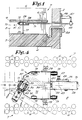
- FIGS. 2 to 5 To clean a steam generator, as shown in fig. 1, a device shown in detail in FIGS. 2 to 5 through an opening 1 in the cylindrical envelope 2, vertical to the generator.
- this generator comprises a bottom plate 3 dividing the interior of the envelope 2 into a lower part 4 and an upper part 5.
- the lower part is divided by a partition into a inlet and outlet for the heating fluid passing through the tubes 6 of a bundle 7 in the shape of an inverted U.
- This bundle 7 is mounted in the upper part 5.
- the end of the tubes 6 of the rising part of the bundle passes through the bottom plate 3 and opens into the aforementioned inlet.
- the tubes 6 of the descending part of the bundle 7 also pass through their bottom end this bottom plate 3 and lead to the abovementioned outlet.
- a free space 8 is formed in which the device for cleaning can be introduced.
- a horizontal distribution plate 9 This plate is crossed by the tubes 6 and is fixed to an inner cylindrical envelope not shown in the figures.
- the opening 1 opens between the bottom plate 3 and the distribution plate 9 on the space 8, near the last plate.
- the tubes 6 of the bundle 7 are arranged in a triangle design.
- the rows of tubes 6 make angles of 30, 90 and 150 degrees with the plane of symmetry of the free space 8.
- the device must spray liquid between these rows to clean the part of the generator located between the bottom plate 3 and the distribution plate 9, part where deposits are formed which must be removed regularly.
- the device is moved in a discontinuous manner parallel to the above-mentioned plane of symmetry and to the bottom plate 3, stopping the device each time so that it can spray liquid at high pressure between one or more pairs of adjacent rows .
- the direction in which the device is moved is indicated below by the longitudinal direction.
- the device comprises a carriage 10 consisting of a hollow hollow base section 11 and a wider mounting box 12 fixed to this section 11.
- wheels 13 projecting through openings 14 in the upper wall of the box. Two wheels are mounted at the front, the other two in protruding parts at the rear. These wheels 13, the axis of rotation of which is transverse, roll on the lower surface of the distribution plate 9.
- front and rear have been considered in relation to the normal direction of advance of the device which is pushed by a high pressure lance 15. It is however obvious that cleaning can be carried out while the device is moving in opposite direction and is therefore drawn by the lance 15.
- an axis 16 on which is fixed a retractable foot 17 which carries at its end and by means of a hydraulic cylinder 18, a transverse axle 19 carrying at its ends a wheel 20.
- this foot In position working, shown in Figures 2 to 4, this foot extends vertically downward, through an opening in the profile 11 and the wheels 20 are supported on the bottom plate 3.
- the cylinder 18 allows to tighten the device between the bottom plate 3 and the distribution plate 9 thus ensuring firm contact between the wheels 13 and the last plate of a part and the wheels 20 and the bottom plate 3 on the other hand.
- the foot 17 In the retracted position, the foot 17 extends horizontally forwards, partly in the profile 11 which is open downwards at the front, which allows the device to pass through the opening 1.
- the pivoting of the foot 17 is effected by means of two racks 21 moving in the longitudinal direction in the opposite direction, on guides 22 mounted on the upper and lower walls of the profile 11, inside the latter.
- the two racks 21 cooperate with the same toothed wheel 23 fixed on the axis 16.
- These racks 21 also cooperate with a second toothed wheel 24 fixed on a transverse axis 25 housed in the profile 11.
- a lever 26 is fixed at one end in projection of this axis 25 and is provided at its free end with a handle 27 at the same time forming a lock blocking the lever 26 to a support 28 fixed to the rear of the box 12, on the profile 11.
- the handle 27 carries a axial pin passing through the lever 26 and entering a notch in the support 28. This handle can be moved axially against a spring in order to remove the pin from the notch, thereby releasing the lever 26.
- the box 12 carries two hydraulic cylinders 29 directed laterally tightening, during a device stop and therefore during spraying, the carriage 10 between two tubes 6 being on either side of the space 8, as shown in fig. 4.
- the device is thus blocked in the horizontal direction while at the same time it is blocked in the vertical direction by the jack 18 as explained above.
- the lines for the liquid for the jacks 18 and 29 and which extend essentially along the lance 15 have not been shown in the figures.
- a spray head On a front part of the profile 11, protruding from the box 12 and partly in the box 12 open at the front, is mounted a spray head, adjustable around a vertical axis.
- This head consists of a support 30, a cylindrical injector holder 31 housed in this support and several injectors 32 mounted in the injector holder 31, the jets of which are directed radially.
- the support 30 can be adjusted in the direction around a vertical axis and for this purpose carries a vertical threaded axis 33 housed in the upper wall of the profile 11.
- a nut 34 screwed onto the axis 33 makes it possible to block the support 30 in a determined position.
- the injector holder 31 is mounted for rotation about its longitudinal axis in a bearing mounted in the support 30.
- This injector holder 31 consists of three detachable parts and is provided with an axial channel 35. In the central part, this channel 35 communicates with two series of three radial channels 36 each opening onto an injector 32.
- first rigid but detachable connection 37 between the injector holder 31 and a hollow high pressure hose 38 which extends through the box 12 and rests on the bottom wall thereof.
- this first connection comprises on the one hand an end piece 39 fixed on one end of the hose 38 and carrying a nut 40 and on the other hand a threaded tube 41 secured to, for example screwed into, the injector holder 31.
- the connection 37 In tightening the nut 40 on this tube 41, the hose 38 and the nozzle holder 31 are made integral, the connection 37 thus transmitting a rotation of the hose 38 to the nozzle holder 31.
- connection 42 also comprises an end piece 39 fixed to the hose 38 and carrying a nut 40, of a on the other hand, and a threaded tube 41 fixed to a nozzle 43 itself fixed to the lance 15.
- the latter end piece 43 is housed in the above-mentioned support 28.
- the support 28 is mounted in an adjustable manner using two screws 44 on the profile 11.
- the hose 38 When the injector holder 31 is directed laterally as shown in FIG. 4 the hose 38 must describe a curve and the connection 42 must be in the most advanced position.
- the connection 42 When the injector holder 31 is in the extension of the longitudinal axis of the carriage 10, the connection 42 must be in a position further back in order to avoid bending of the hose 38.
- the device described is very compact, especially if the foot 17 is retracted. With the retracted foot, the introduction and exit of the device through the opening 1 is very easy.
- the drive of the injector holder 31 and more particularly the oscillation of the latter is done using the lance 15.
- This lance which is rigid, also ensures the intermittent movement of the carriage 10.
- the lance is oscillated by a motor 45 mounted on a flange 46 which is fixed outside the casing 2, around the opening 1.
- a cylinder and piston device 47, also mounted on this flange ensures the intermittent longitudinal displacement of spear 15.
- the handle 27 is released by means of a hook inserted through the opening 1 and the lever 26 is pivoted so as to take out the foot 17. Then the carriage 10 is clamped, when it is in a position in which the injectors 32 can spray between one or more pairs of rows of tubes 6, between the bottom plate 3 and the distribution plate 9 on the one hand and between two tubes 5 on either side of the space 8 on the other hand. After spraying, the carriage 10 is loosened, advanced by one step and tightened, after which the injector holder is again oscillated to spray between other rows. After one or more crossings of the free space 8, the carriage 10 is removed and possibly replaced with the injector holder 31 fixed in another position and the above operation is repeated. The sprayed liquid is collected on the bottom plate 3 and aspirated through suction lines 48.
- the construction and handling of the device is very simple.
- the number and nature of the injectors are easily changeable and the hose is also easily replaceable.
Landscapes
- Physics & Mathematics (AREA)
- Engineering & Computer Science (AREA)
- High Energy & Nuclear Physics (AREA)
- Thermal Sciences (AREA)
- Mechanical Engineering (AREA)
- General Engineering & Computer Science (AREA)
- Cleaning By Liquid Or Steam (AREA)
Priority Applications (2)
| Application Number | Priority Date | Filing Date | Title |
|---|---|---|---|
| BE9000639A BE1004430A3 (fr) | 1990-06-22 | 1990-06-22 | Dispositif pour le nettoyage d'un generateur de vapeur. |
| EP92203215A EP0593818A1 (de) | 1990-06-22 | 1992-10-20 | Reinigungsgerät für Dampferzeuger |
Applications Claiming Priority (2)
| Application Number | Priority Date | Filing Date | Title |
|---|---|---|---|
| BE9000639A BE1004430A3 (fr) | 1990-06-22 | 1990-06-22 | Dispositif pour le nettoyage d'un generateur de vapeur. |
| EP92203215A EP0593818A1 (de) | 1990-06-22 | 1992-10-20 | Reinigungsgerät für Dampferzeuger |
Publications (1)
| Publication Number | Publication Date |
|---|---|
| EP0593818A1 true EP0593818A1 (de) | 1994-04-27 |
Family
ID=25662534
Family Applications (1)
| Application Number | Title | Priority Date | Filing Date |
|---|---|---|---|
| EP92203215A Ceased EP0593818A1 (de) | 1990-06-22 | 1992-10-20 | Reinigungsgerät für Dampferzeuger |
Country Status (2)
| Country | Link |
|---|---|
| EP (1) | EP0593818A1 (de) |
| BE (1) | BE1004430A3 (de) |
Cited By (3)
| Publication number | Priority date | Publication date | Assignee | Title |
|---|---|---|---|---|
| EP0696719A1 (de) * | 1994-08-12 | 1996-02-14 | Framatome | Flüssigkeitsstrahl-Reinigungsvorrichtung für Rohrplatte eines Wärmetauschers und deren Verwendung |
| WO2001048434A1 (en) * | 1999-12-23 | 2001-07-05 | Olmi S.P.A. | Tube nest heat exchanger with cleaning access |
| GB2558616A (en) * | 2017-01-10 | 2018-07-18 | Cape Environmental Services Onshore Ltd | Biomass boiler cleaning method and apparatus |
Families Citing this family (1)
| Publication number | Priority date | Publication date | Assignee | Title |
|---|---|---|---|---|
| BE1004430A3 (fr) * | 1990-06-22 | 1992-11-17 | Innus Ind Nuclear Service | Dispositif pour le nettoyage d'un generateur de vapeur. |
Citations (3)
| Publication number | Priority date | Publication date | Assignee | Title |
|---|---|---|---|---|
| EP0255503A2 (de) * | 1986-07-29 | 1988-02-03 | Smet Jet N.V. | Wasserstrahlreinigung von Dampferzeugern |
| DE3806004A1 (de) * | 1987-02-26 | 1988-09-08 | Innus Ind Nuclear Service | Reinigungsgeraet fuer einen waermetauscher |
| BE1004430A3 (fr) * | 1990-06-22 | 1992-11-17 | Innus Ind Nuclear Service | Dispositif pour le nettoyage d'un generateur de vapeur. |
-
1990
- 1990-06-22 BE BE9000639A patent/BE1004430A3/fr not_active IP Right Cessation
-
1992
- 1992-10-20 EP EP92203215A patent/EP0593818A1/de not_active Ceased
Patent Citations (3)
| Publication number | Priority date | Publication date | Assignee | Title |
|---|---|---|---|---|
| EP0255503A2 (de) * | 1986-07-29 | 1988-02-03 | Smet Jet N.V. | Wasserstrahlreinigung von Dampferzeugern |
| DE3806004A1 (de) * | 1987-02-26 | 1988-09-08 | Innus Ind Nuclear Service | Reinigungsgeraet fuer einen waermetauscher |
| BE1004430A3 (fr) * | 1990-06-22 | 1992-11-17 | Innus Ind Nuclear Service | Dispositif pour le nettoyage d'un generateur de vapeur. |
Cited By (4)
| Publication number | Priority date | Publication date | Assignee | Title |
|---|---|---|---|---|
| EP0696719A1 (de) * | 1994-08-12 | 1996-02-14 | Framatome | Flüssigkeitsstrahl-Reinigungsvorrichtung für Rohrplatte eines Wärmetauschers und deren Verwendung |
| FR2723634A1 (fr) * | 1994-08-12 | 1996-02-16 | Framatome Sa | Dispositif de nettoyage par jet de liquide d'une plaque tubulaire d'un echangeur de chaleur et utilisation. |
| WO2001048434A1 (en) * | 1999-12-23 | 2001-07-05 | Olmi S.P.A. | Tube nest heat exchanger with cleaning access |
| GB2558616A (en) * | 2017-01-10 | 2018-07-18 | Cape Environmental Services Onshore Ltd | Biomass boiler cleaning method and apparatus |
Also Published As
| Publication number | Publication date |
|---|---|
| BE1004430A3 (fr) | 1992-11-17 |
Similar Documents
| Publication | Publication Date | Title |
|---|---|---|
| EP0780627B1 (de) | Verfahren und Vorrichtung zur Reinigung der Endplatte eines Wärmetauschers vom Innern des Wärmetauscherbündels | |
| EP0314019A2 (de) | Poliermaschine mit einer drehenden Scheibe mit einem oder mehreren daran befestigten Köpfen | |
| CH654777A5 (fr) | Machine pour decouper par electro-erosion. | |
| EP0631089B1 (de) | Vorrichtung zum Entfernen von Ablagerungen von dem Rohrboden eines Dampferzeugers | |
| FR2563331A1 (fr) | Procede et appareillage pour le nettoyage des faisceaux de tubes des echangeurs et ensembles analogues | |
| EP0388296B1 (de) | Interventionsvorrichtung, insbesondere zur Prüfung, Inspektion und Wartung von Wärmeaustauschern | |
| BE1004430A3 (fr) | Dispositif pour le nettoyage d'un generateur de vapeur. | |
| EP0559541B1 (de) | Reinigungsinstallation für Behälter wie Müllkästen | |
| FR2550967A1 (fr) | Procede de nettoyage d'un generateur de vapeur | |
| EP2577158B1 (de) | Vorrichtung zur führung einer flexiblen lanzette | |
| EP2998963B1 (de) | Führungsvorrichtung für flexiblen lanze | |
| EP0063073B1 (de) | Vorrichtung zum Positionieren eines Gerätes in den Öffnungen einer Rohrplatte | |
| FR2683473A1 (fr) | Dispositif de travail au laser a l'interieur d'un element tubulaire. | |
| EP0766040A1 (de) | Vorrichtung zur Reinigung eines Dampferzeugers mit einem Wasserwerfer | |
| EP0433179B1 (de) | Verfahren für das Ersetzen einer Heizung eines Druckausgleichgefässes in einem Kernreaktor und in einem solchen Verfahren verwendete Vorrichtung | |
| FR2972071A1 (fr) | Dispositif d'inspection d'un generateur de vapeur | |
| EP0038270B1 (de) | Mittel zum Unterstützen und Verschieben eines Werkzeuges an der Innenseite eines Loches | |
| CH587117A5 (en) | Extruder die turret supporting alternative extrusion dies - for rapid changeover of coating dies to suit different profiles | |
| EP0696719A1 (de) | Flüssigkeitsstrahl-Reinigungsvorrichtung für Rohrplatte eines Wärmetauschers und deren Verwendung | |
| FR2674466A1 (fr) | Procede et dispositif d'ebavurage notamment d'une bande d'acier decoupee en brame. | |
| EP0023008A1 (de) | Bewegbare Maschine zum Waschen von Gemüsen | |
| FR2684482A1 (fr) | Dispositif d'intervention dans un espace delimite par une enveloppe cylindrique comportant au moins deux ouvertures diametralement opposees. | |
| EP0082069A1 (de) | Trage- und Verschiebevorrichtung für Werkzeuge um ein Rohrbündel auf einer rohrförmigen Platte eines Dampfgenerators zu befestigen | |
| FR2914394A1 (fr) | Dispositif d'insertion d'un outillage, notamment d'une sonde a l'interieur d'un generateur de vapeur. | |
| FR2738053A1 (fr) | Installation pour le nettoyage a la lance a eau d'un generateur de vapeur et son procede de mise en oeuvre |
Legal Events
| Date | Code | Title | Description |
|---|---|---|---|
| PUAI | Public reference made under article 153(3) epc to a published international application that has entered the european phase |
Free format text: ORIGINAL CODE: 0009012 |
|
| AK | Designated contracting states |
Kind code of ref document: A1 Designated state(s): DE ES FR SE |
|
| 17P | Request for examination filed |
Effective date: 19940623 |
|
| 17Q | First examination report despatched |
Effective date: 19950706 |
|
| GRAG | Despatch of communication of intention to grant |
Free format text: ORIGINAL CODE: EPIDOS AGRA |
|
| 18R | Application refused |
Effective date: 19960721 |