EP0593860B1 - Boîtier helicoidal pour soufflante radial - Google Patents
Boîtier helicoidal pour soufflante radial Download PDFInfo
- Publication number
- EP0593860B1 EP0593860B1 EP93111713A EP93111713A EP0593860B1 EP 0593860 B1 EP0593860 B1 EP 0593860B1 EP 93111713 A EP93111713 A EP 93111713A EP 93111713 A EP93111713 A EP 93111713A EP 0593860 B1 EP0593860 B1 EP 0593860B1
- Authority
- EP
- European Patent Office
- Prior art keywords
- deep
- housing part
- housing
- collar
- side wall
- Prior art date
- Legal status (The legal status is an assumption and is not a legal conclusion. Google has not performed a legal analysis and makes no representation as to the accuracy of the status listed.)
- Expired - Lifetime
Links
- 239000000463 material Substances 0.000 claims abstract description 18
- 238000009423 ventilation Methods 0.000 claims abstract description 11
- 239000004033 plastic Substances 0.000 claims abstract description 8
- 229920003023 plastic Polymers 0.000 claims abstract description 8
- 210000001331 nose Anatomy 0.000 claims abstract 4
- 238000000465 moulding Methods 0.000 claims 1
- 238000010276 construction Methods 0.000 abstract description 2
- 230000002093 peripheral effect Effects 0.000 description 8
- 239000004793 Polystyrene Substances 0.000 description 4
- 238000002347 injection Methods 0.000 description 3
- 239000007924 injection Substances 0.000 description 3
- 238000003801 milling Methods 0.000 description 3
- 238000013016 damping Methods 0.000 description 2
- 238000004519 manufacturing process Methods 0.000 description 2
- 239000002184 metal Substances 0.000 description 2
- 229920002223 polystyrene Polymers 0.000 description 2
- 239000004800 polyvinyl chloride Substances 0.000 description 2
- 238000001816 cooling Methods 0.000 description 1
- 230000008878 coupling Effects 0.000 description 1
- 238000010168 coupling process Methods 0.000 description 1
- 238000005859 coupling reaction Methods 0.000 description 1
- 238000009434 installation Methods 0.000 description 1
- 238000009413 insulation Methods 0.000 description 1
- 238000011031 large-scale manufacturing process Methods 0.000 description 1
- 238000003754 machining Methods 0.000 description 1
- 239000002985 plastic film Substances 0.000 description 1
- 230000000717 retained effect Effects 0.000 description 1
- 239000000725 suspension Substances 0.000 description 1
- 239000002023 wood Substances 0.000 description 1
Images
Classifications
-
- F—MECHANICAL ENGINEERING; LIGHTING; HEATING; WEAPONS; BLASTING
- F04—POSITIVE - DISPLACEMENT MACHINES FOR LIQUIDS; PUMPS FOR LIQUIDS OR ELASTIC FLUIDS
- F04D—NON-POSITIVE-DISPLACEMENT PUMPS
- F04D29/00—Details, component parts, or accessories
- F04D29/40—Casings; Connections of working fluid
- F04D29/42—Casings; Connections of working fluid for radial or helico-centrifugal pumps
- F04D29/4206—Casings; Connections of working fluid for radial or helico-centrifugal pumps especially adapted for elastic fluid pumps
- F04D29/4226—Fan casings
-
- F—MECHANICAL ENGINEERING; LIGHTING; HEATING; WEAPONS; BLASTING
- F04—POSITIVE - DISPLACEMENT MACHINES FOR LIQUIDS; PUMPS FOR LIQUIDS OR ELASTIC FLUIDS
- F04D—NON-POSITIVE-DISPLACEMENT PUMPS
- F04D29/00—Details, component parts, or accessories
- F04D29/60—Mounting; Assembling; Disassembling
- F04D29/62—Mounting; Assembling; Disassembling of radial or helico-centrifugal pumps
- F04D29/624—Mounting; Assembling; Disassembling of radial or helico-centrifugal pumps especially adapted for elastic fluid pumps
- F04D29/626—Mounting or removal of fans
Definitions
- the invention relates to a spiral housing made of plastic material for radial fans for decentralized room ventilation, which has a closed side wall, a side wall provided with a suction opening and a spiral circumferential wall arranged between them, which is provided with a tangentially adjoining outlet opening, consisting of two along a normal housing parts interconnected to the plane of the fan axis.
- Radial blowers with a spiral housing made of plastic material are used as cooling and / or circulating air blowers in household appliances and are required for this purpose in quantities that enable large-scale production.
- the spiral housing is manufactured as injection molded parts that have a design adapted to the intended use.
- the known radial fans with spiral housings made of plastic material are not readily usable, because the spiral housings must be given a different design.
- the injection molds for the manufacture of the spiral housing require a high cost, but ventilation devices for decentralized room ventilation are only required in relatively small numbers, it is not worthwhile to provide special injection molds for this, which then require a very long payback period.
- radial ventilation fans are used in room ventilation devices, which are usually equipped with spiral housings made of sheet metal (for example US Pat. No. 2,456,488). are equipped and are available relatively inexpensively.
- the radial fans cause a relatively strong intrinsic noise resulting from vibrations of the sheet metal housing during operation, which must be counteracted by additional measures, in particular elastic suspensions and brackets.
- the aim of the invention is to create a spiral housing made of plastic material, which can still be produced inexpensively even in small quantities and which has a high internal damping, which enables a simplified installation of the radial blowers in room ventilation devices, in particular sound insulation fans.
- Forming tools that enable vacuum deformation of flat sheet material into deep-drawn bodies can be produced relatively easily and inexpensively, for example from wood, and be designed so that the side wall and The edge or collar of the deep-drawn body that can be assembled into the spiral housing is given an optimally streamlined shape.
- the end edges of the rim or collar on the second deep-drawn body can be reworked, for example with the help of a freely programmable five-axis milling machine, so that the outwardly projecting lugs are retained on them.
- the recesses can be made in the same manner in the edge or collar of the first deep-drawn body near the side wall with the aid of a finger cutter.
- the sheet material used to manufacture the vacuum deep-drawn body can be, for example, polyvinyl chloride (PVC), standard polystyrene (PS) or impact-resistant polystyrene (SB), the inherent elasticity of which ensures that the lugs on the edge or collar of the second deep-drawn body provide an automatic and secure snap connection enter with the recesses in the rim or collar of the first deep-drawn body when the two deep-drawn bodies are plugged together axially parallel to their edge rims or collar.
- PVC polyvinyl chloride
- PS standard polystyrene
- SB impact-resistant polystyrene
- a flat, circular bowl is formed from the side wall of the first deep-drawing body, the center of which has a cover position with the center of the volute casing, that the bowl bottom has an inwardly arched shape, and that bayonet-like openings are provided in the peripheral wall of the cup, in which the stator of a blower motor via radial arms against the spring force of the arched Cup base - can be locked by a simple, limited angular rotation relative to the deep-drawn body.
- the bayonet-like openings in the peripheral wall of the bowl can also be produced in a simple manner, for example with the aid of a freely programmable five-axis milling machine.
- corresponding passage openings for the radial arms on the stator of the blower motor in the side wall of the first deep-drawn molded part can also be provided with the bayonet-like openings in the peripheral wall of the cup.
- a hump or knobs can be formed from the side wall of the first deep-drawn body in such a way that it lies in the rotating circle area of the radial arms of the blower motor stator and thereby comes into operative connection with one of the radial arms in its engagement position as a rotational position lock.
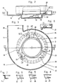
- a radial fan 1 is shown in cross section, in which a fan wheel 3 is accommodated in a so-called spiral housing 2, which sits on the rotor 4 of an electric motor 5, which in turn is fastened in the spiral housing 2.
- the entire radial fan 1 with spiral housing 2, impeller 3, rotor 4 and electric motor 5 has a relative small and flat design, as clearly shown in Fig. 1 of the drawing.
- the spiral housing 2 of the radial fan 1 is composed of two housing parts 6 and 7, which are connected to one another along a plane 9-9 lying normal to the fan axis 8-8.
- Both housing parts 6 and 7 of the spiral housing 2 are produced as vacuum deep-drawn bodies made of a plastic plate material, for example made of polyvinyl chloride (PVC) from standard polystyrene (PS) or impact-resistant polystyrene (SB), by first plasticizing the flat plate material by the action of heat and then by Creation of a vacuum against the contours of a wooden mold or the like is created.
- a plastic plate material for example made of polyvinyl chloride (PVC) from standard polystyrene (PS) or impact-resistant polystyrene (SB)
- the housing part 6 is formed by a first vacuum deep-drawing body, which has a closed side wall 10 and an angled edge rim or collar 11 which adjoins the contour thereof.
- a flat, circular bowl 12 is formed, the center of which coincides with the center of the spiral housing 2 and consequently also has a covering position with the fan axis 8-8.
- the bowl bottom 13 has an inwardly arched shape and in the peripheral wall 14 of the bowl 12 several bayonet-like openings 15, 16, 17 are provided evenly distributed in the circumferential direction, which are only partially shown in FIGS. 4, 5 and 6.
- each of these bayonet-like openings 15, 16, 17 in the peripheral wall 14 of the bowl 12 corresponds to a passage opening 19, 20, 21, which are provided in the side wall 10 of the housing part 6 in a manner which from Fig. 3 of the drawing can be seen.
- the stator 21 hits the inwardly curved cup base 13 and deforms it elastically outwards.
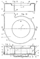
- Slit-like recesses 26 are provided near the side wall 10 in the rim or collar 11 of the housing part 6, namely in a larger number, distributed as uniformly as possible along the circumferential contour. 3 that the housing part 6 is provided with five recesses 26. These recesses 26 can either, as shown in FIG. 2, run straight and parallel to the side wall 10. However, as indicated in FIG. 8, they can also be provided with an arcuate course.
- the housing part 7 of the spiral housing 7 is also produced as a vacuum deep-drawing body made of plate material, in the same way as the housing part 6. It has an essentially flat side wall 27, into which an intake neck 28 is formed as an opening in alignment with the blower axis 8-8.
- the peripheral contour of the second vacuum deep-drawing body forming the housing part 7 is matched to the peripheral contour of the housing part 6.
- the housing part 7 also has a rim or collar 29 directed at right angles to its side wall 27. However, this has a height which approximately corresponds to the inside width 30 of the spiral housing 2, as can be clearly seen from FIG. 1.
- slot-like recesses 26 according to FIG. 2 have to be made relatively narrow if they are to interact with the lugs 32 as a low-play snap-locking device, it is possible in the arcuate configuration according to FIG. 8 to give the recesses 26 a larger opening width. Nevertheless, they interact with the lugs 32 as a low-play snap-in device, because the latter have a three-point system on the arc contour.
- the spiral housing 2 of the radial blowers 1 described above can still be manufactured inexpensively with relatively small quantities and at the same time have the advantage of a relatively high internal damping because they are formed from plastic sheet material by vacuum deformation.
Landscapes
- Engineering & Computer Science (AREA)
- Mechanical Engineering (AREA)
- General Engineering & Computer Science (AREA)
- Structures Of Non-Positive Displacement Pumps (AREA)
Claims (5)
- Carter spiral en matière plastique pour soufflerie radiale pour aération de locaux indépendante, lequel présente une paroi latérale fermée, une paroi latérale munie d'une ouverture d'aspirstion et entre celles-ci une paroi périphérique en spirale qui est équipée d'une ouverture de purge, composé deux pièces de carter (6, 7) reliées entre elles le long d'une surface normalement placée par rapport à l'axe de soufflerie,
caractérisé en ceque les pièces du carter (6 et 7) sont constituées d'un premier et d'un deuxième corps matricés sous vide en lame, chacun présentant un rebord coudé ou une collerette (11, voire 29),que le contour péripnérique du premier corps matricé sous vide (pièce du carter 6) est dimensionné plus généreusement de l'épaisseur de la lame que le contour périphérique du deuxième corps matricé sous vide (pièce du carter 7),que le rebord, voire la collerette (29) du deuxième corps matricé (pièce du carter 7) a une hauteur qui correspond à peu près à la largeur de construction intérieure (30) du carter spiral (2),que sur le deuxième corps matricé sous vide (pièce de carter 7), il y a un plus grand nombre d'ergots (32) le long du contour pêriphérique qui dépassent à partir des extrémités (31) du rebord ou de la collerette (29),et que le premier corps matricé sous vide (pièce du carter 6) contient des évidements (26) sur son rebord ou sa collerette (11) près de la paroi latérale (10) dans lesquels les ergots (32) du rebord ou de la collerette (29) du de deuxième corps matricé sous vide (pièce du carter 7) peuvent s'encliqueter. - Carter spiral selon la revendication 1,
caractérisé en ce que l'ouverture de purge (28) dans la paroi latérale (27) du deuxiéme corps matricé sous vide (pièce du carter 7) a la forme d'un col rentré. - Carter spiral selon l'une des revendications 1 et 2,
caractérisé en ce que le rebord ou la collerette (11) du premier corps matricé sous vide (pièce du carter 6) a une hauteur qui correspond seulement à une fraction de la hauteur du rebord ou de la collerette (29) qui se trouve sur le deuxième corps matricé sous vide (pièce de carter 7). - Carter spiral selon l'une des revendications 1 à 3,
caractérisé en ce qu'il y a une cuvette (12) plate limitée, de forme ronde qui ressort de la paroi latérale (10) du premier corps matricé sous vide (pièce du carter 6), et dont le centre a une position de couverture avec le centre du carter spiral, que le fond de la cuvette (13) a une forme incurvée vers l'intérieur et que l'on a prévu des ouvertures à baïonnette (15, 16, 17) dans la paroi périphérique (14) de la cuvette (12), dans lesquelles le stator (21) d'un moteur de ventilateur (5) est verrouillable par des bras radiaux (22, 23, 24) contre l'effet de ressort du fond de la cuvette incurvé (13). - Carter spiral selon l'une des revendications 1 à 4,
caractérisé en ce, qu'avec les ouvertures à baïonnette (15, 16, 17) dans la paroi periphériqué (14) de la cuve (12), on a prévu des ouvertures de passage correspondantes (18,19,20) pour les bras radiaux (22, 23, 24) du stator du moteur de ventilateur (21) dans la paroi latérale (10) du premier corps matricé (pièce de carter 6).
Applications Claiming Priority (2)
| Application Number | Priority Date | Filing Date | Title |
|---|---|---|---|
| DE9214308U | 1992-10-23 | ||
| DE9214308U DE9214308U1 (de) | 1992-10-23 | 1992-10-23 | Spiralgehäuse für Radialgebläse |
Publications (2)
| Publication Number | Publication Date |
|---|---|
| EP0593860A1 EP0593860A1 (fr) | 1994-04-27 |
| EP0593860B1 true EP0593860B1 (fr) | 1996-02-07 |
Family
ID=6885130
Family Applications (1)
| Application Number | Title | Priority Date | Filing Date |
|---|---|---|---|
| EP93111713A Expired - Lifetime EP0593860B1 (fr) | 1992-10-23 | 1993-07-22 | Boîtier helicoidal pour soufflante radial |
Country Status (3)
| Country | Link |
|---|---|
| EP (1) | EP0593860B1 (fr) |
| AT (1) | ATE134026T1 (fr) |
| DE (2) | DE9214308U1 (fr) |
Families Citing this family (6)
| Publication number | Priority date | Publication date | Assignee | Title |
|---|---|---|---|---|
| DE4321924C1 (de) * | 1993-07-01 | 1994-06-23 | Siegenia Frank Kg | Verfahren zum Herstellen eines Radiallüfters und hiernach hergestellter Radiallüfter |
| FR2831931B1 (fr) * | 2001-11-02 | 2005-08-26 | Valeo Climatisation | Groupe moto-ventilateur a support moteur desaxe |
| WO2003038285A1 (fr) * | 2001-11-02 | 2003-05-08 | Valeo Climatisation | Groupe moto-ventilateur |
| DE102005059636A1 (de) * | 2005-12-14 | 2007-06-21 | Pfeiffer Vacuum Gmbh | Vakuumpumpe |
| CN109083853A (zh) * | 2018-10-24 | 2018-12-25 | 奥克斯空调股份有限公司 | 一种风机结构以及空调器 |
| DE102019129588A1 (de) * | 2019-11-04 | 2021-05-06 | Miele & Cie. Kg | Gebläse, umfassend ein Gehäuse und einen Motor |
Family Cites Families (9)
| Publication number | Priority date | Publication date | Assignee | Title |
|---|---|---|---|---|
| US2456488A (en) * | 1945-03-15 | 1948-12-14 | Torrington Mfg Co | Centrifugal blower housing |
| US2931562A (en) * | 1958-01-20 | 1960-04-05 | Brown & Bigelow | Desk air fan |
| DE1300623B (de) * | 1959-10-06 | 1969-08-07 | Danieels Warmte En Kunststofte | Aus Kunststoff bestehendes Gehaeuse eines Zentrifugalventilators |
| DE6605373U (de) * | 1960-08-19 | 1970-05-14 | Kiefer A | Gehaeuse von zentrifugal-ventilatoren aus kunststoff |
| DE1282836B (de) * | 1960-08-19 | 1968-11-14 | Alice Kiefer Geb Strelow | Verfahren zum Herstellen von Gehaeusen von Zentrifugal-Ventilatoren aus Kunststoff |
| US3154242A (en) * | 1963-06-20 | 1964-10-27 | Rotron Mfg Co | Fan |
| DE1816446A1 (de) * | 1968-12-21 | 1970-07-23 | Siemens Ag | Verfahren zum Herstellen von Spiralgehaeusen fuer Radialgeblaese |
| GB2002182B (en) * | 1977-07-30 | 1982-03-24 | Matsushita Electric Works Ltd | Device for fitting electric motors and for feeding power to the same |
| DE2807273C2 (de) * | 1978-02-21 | 1985-07-18 | Robert Bosch Gmbh, 7000 Stuttgart | Radialgebläse, insbesondere für Heizungen und Klimaanlagen in Kraftfahrzeugen |
-
1992
- 1992-10-23 DE DE9214308U patent/DE9214308U1/de not_active Expired - Lifetime
-
1993
- 1993-07-22 EP EP93111713A patent/EP0593860B1/fr not_active Expired - Lifetime
- 1993-07-22 AT AT93111713T patent/ATE134026T1/de not_active IP Right Cessation
- 1993-07-22 DE DE59301590T patent/DE59301590D1/de not_active Expired - Fee Related
Also Published As
| Publication number | Publication date |
|---|---|
| DE59301590D1 (de) | 1996-03-21 |
| EP0593860A1 (fr) | 1994-04-27 |
| ATE134026T1 (de) | 1996-02-15 |
| DE9214308U1 (de) | 1993-01-07 |
Similar Documents
| Publication | Publication Date | Title |
|---|---|---|
| DE602004002548T2 (de) | Gebläsemotor | |
| EP0642206B2 (fr) | Support pour un moteur électrique, en particulier pour un ventilateur d'un appareil de chauffage ou de climatisation | |
| DE102013105524B4 (de) | Radiallüfter | |
| DE69609800T2 (de) | Geformte, durchströmte Motoranordnung | |
| DE3632993C2 (fr) | ||
| EP0593860B1 (fr) | Boîtier helicoidal pour soufflante radial | |
| EP2338581A1 (fr) | Unité de ventilateur pour ventilateur à filtre | |
| DE102014009146A1 (de) | Elektromotor mit einem Rotor, einem Stator und einem Elektronikgehäuse sowie Lüfterrad für einen Elektromotor | |
| DE2037993B2 (de) | Gehaeuse fuer kleinmotoren | |
| DE1428227A1 (de) | Geblaesegehaeuse | |
| DE4421855B4 (de) | Kompakte Gebläseeinheit für Kraftfahrzeuge | |
| DE4427115C1 (de) | Laufrad für ein Radialgebläse | |
| EP0615069B1 (fr) | Roue de ventilateur | |
| DE3631942C2 (fr) | ||
| DE3735734C2 (fr) | ||
| DE7622070U1 (de) | Selbstreinigende wasserableitpumpe, insbesondere fuer waschmaschinen | |
| DE102011000208A1 (de) | Laufrad für ein Gebläse | |
| EP3421806B1 (fr) | Ventilateur | |
| DE9422144U1 (de) | Halterung für einen Elektromotor, insbesondere für ein Gebläserad einer Heizungs- oder Klimaanlage | |
| EP0260501A1 (fr) | Pompe entraînée par un électromoteur | |
| DE10258346A1 (de) | Bürstenloser Elektromotor | |
| DE10038057B4 (de) | Filterlüfter | |
| EP1258636B1 (fr) | Rotor ventilateur et ventilateur, en particulier ventilateur radial | |
| EP0761976B1 (fr) | Procédé de fabrication d'un boítier d'un ventilateur | |
| DE19500994A1 (de) | Laufrad für ein Radialgebläse |
Legal Events
| Date | Code | Title | Description |
|---|---|---|---|
| PUAI | Public reference made under article 153(3) epc to a published international application that has entered the european phase |
Free format text: ORIGINAL CODE: 0009012 |
|
| AK | Designated contracting states |
Kind code of ref document: A1 Designated state(s): AT BE CH DE DK ES FR GB IT LI NL |
|
| 17P | Request for examination filed |
Effective date: 19940507 |
|
| 17Q | First examination report despatched |
Effective date: 19950725 |
|
| GRAA | (expected) grant |
Free format text: ORIGINAL CODE: 0009210 |
|
| AK | Designated contracting states |
Kind code of ref document: B1 Designated state(s): AT BE CH DE DK ES FR GB IT LI NL |
|
| PG25 | Lapsed in a contracting state [announced via postgrant information from national office to epo] |
Ref country code: NL Free format text: LAPSE BECAUSE OF FAILURE TO SUBMIT A TRANSLATION OF THE DESCRIPTION OR TO PAY THE FEE WITHIN THE PRESCRIBED TIME-LIMIT Effective date: 19960207 Ref country code: IT Free format text: LAPSE BECAUSE OF FAILURE TO SUBMIT A TRANSLATION OF THE DESCRIPTION OR TO PAY THE FEE WITHIN THE PRE;WARNING: LAPSES OF ITALIAN PATENTS WITH EFFECTIVE DATE BEFORE 2007 MAY HAVE OCCURRED AT ANY TIME BEFORE 2007. THE CORRECT EFFECTIVE DATE MAY BE DIFFERENT FROM THE ONE RECORDED.SCRIBED TIME-LIMIT Effective date: 19960207 Ref country code: GB Effective date: 19960207 Ref country code: FR Effective date: 19960207 Ref country code: ES Free format text: THE PATENT HAS BEEN ANNULLED BY A DECISION OF A NATIONAL AUTHORITY Effective date: 19960207 Ref country code: DK Effective date: 19960207 Ref country code: BE Effective date: 19960207 |
|
| REF | Corresponds to: |
Ref document number: 134026 Country of ref document: AT Date of ref document: 19960215 Kind code of ref document: T |
|
| REF | Corresponds to: |
Ref document number: 59301590 Country of ref document: DE Date of ref document: 19960321 |
|
| REG | Reference to a national code |
Ref country code: CH Ref legal event code: NV Representative=s name: PATENTANWAELTE GEORG ROEMPLER UND ALDO ROEMPLER |
|
| NLV1 | Nl: lapsed or annulled due to failure to fulfill the requirements of art. 29p and 29m of the patents act | ||
| EN | Fr: translation not filed | ||
| GBV | Gb: ep patent (uk) treated as always having been void in accordance with gb section 77(7)/1977 [no translation filed] |
Effective date: 19960207 |
|
| PLBQ | Unpublished change to opponent data |
Free format text: ORIGINAL CODE: EPIDOS OPPO |
|
| PLBI | Opposition filed |
Free format text: ORIGINAL CODE: 0009260 |
|
| PLBF | Reply of patent proprietor to notice(s) of opposition |
Free format text: ORIGINAL CODE: EPIDOS OBSO |
|
| 26 | Opposition filed |
Opponent name: LUNOS-LUEFTUNG GMBH & CO. VENTILATOREN KG Effective date: 19961107 |
|
| PLBF | Reply of patent proprietor to notice(s) of opposition |
Free format text: ORIGINAL CODE: EPIDOS OBSO |
|
| PLBO | Opposition rejected |
Free format text: ORIGINAL CODE: EPIDOS REJO |
|
| PLBN | Opposition rejected |
Free format text: ORIGINAL CODE: 0009273 |
|
| STAA | Information on the status of an ep patent application or granted ep patent |
Free format text: STATUS: OPPOSITION REJECTED |
|
| 27O | Opposition rejected |
Effective date: 19971027 |
|
| PGFP | Annual fee paid to national office [announced via postgrant information from national office to epo] |
Ref country code: AT Payment date: 20060720 Year of fee payment: 14 |
|
| PGFP | Annual fee paid to national office [announced via postgrant information from national office to epo] |
Ref country code: CH Payment date: 20060724 Year of fee payment: 14 |
|
| PGFP | Annual fee paid to national office [announced via postgrant information from national office to epo] |
Ref country code: DE Payment date: 20060731 Year of fee payment: 14 |
|
| REG | Reference to a national code |
Ref country code: CH Ref legal event code: PL |
|
| PG25 | Lapsed in a contracting state [announced via postgrant information from national office to epo] |
Ref country code: LI Free format text: LAPSE BECAUSE OF NON-PAYMENT OF DUE FEES Effective date: 20070731 Ref country code: DE Free format text: LAPSE BECAUSE OF NON-PAYMENT OF DUE FEES Effective date: 20080201 Ref country code: CH Free format text: LAPSE BECAUSE OF NON-PAYMENT OF DUE FEES Effective date: 20070731 |
|
| PG25 | Lapsed in a contracting state [announced via postgrant information from national office to epo] |
Ref country code: AT Free format text: LAPSE BECAUSE OF NON-PAYMENT OF DUE FEES Effective date: 20070722 |