EP0593934B1 - Dispositif de fixation pour un appareil électrique - Google Patents
Dispositif de fixation pour un appareil électrique Download PDFInfo
- Publication number
- EP0593934B1 EP0593934B1 EP93115405A EP93115405A EP0593934B1 EP 0593934 B1 EP0593934 B1 EP 0593934B1 EP 93115405 A EP93115405 A EP 93115405A EP 93115405 A EP93115405 A EP 93115405A EP 0593934 B1 EP0593934 B1 EP 0593934B1
- Authority
- EP
- European Patent Office
- Prior art keywords
- holding device
- clamping
- lever
- electrical apparatus
- limbs
- Prior art date
- Legal status (The legal status is an assumption and is not a legal conclusion. Google has not performed a legal analysis and makes no representation as to the accuracy of the status listed.)
- Expired - Lifetime
Links
Images

Classifications
-
- F—MECHANICAL ENGINEERING; LIGHTING; HEATING; WEAPONS; BLASTING
- F16—ENGINEERING ELEMENTS AND UNITS; GENERAL MEASURES FOR PRODUCING AND MAINTAINING EFFECTIVE FUNCTIONING OF MACHINES OR INSTALLATIONS; THERMAL INSULATION IN GENERAL
- F16M—FRAMES, CASINGS OR BEDS OF ENGINES, MACHINES OR APPARATUS, NOT SPECIFIC TO ENGINES, MACHINES OR APPARATUS PROVIDED FOR ELSEWHERE; STANDS; SUPPORTS
- F16M13/00—Other supports for positioning apparatus or articles; Means for steadying hand-held apparatus or articles
- F16M13/02—Other supports for positioning apparatus or articles; Means for steadying hand-held apparatus or articles for supporting on, or attaching to, an object, e.g. tree, gate, window-frame, cycle
-
- B—PERFORMING OPERATIONS; TRANSPORTING
- B60—VEHICLES IN GENERAL
- B60R—VEHICLES, VEHICLE FITTINGS, OR VEHICLE PARTS, NOT OTHERWISE PROVIDED FOR
- B60R11/00—Arrangements for holding or mounting articles, not otherwise provided for
- B60R11/02—Arrangements for holding or mounting articles, not otherwise provided for for radio sets, television sets, telephones, or the like; Arrangement of controls thereof
- B60R11/0241—Arrangements for holding or mounting articles, not otherwise provided for for radio sets, television sets, telephones, or the like; Arrangement of controls thereof for telephones
-
- F—MECHANICAL ENGINEERING; LIGHTING; HEATING; WEAPONS; BLASTING
- F16—ENGINEERING ELEMENTS AND UNITS; GENERAL MEASURES FOR PRODUCING AND MAINTAINING EFFECTIVE FUNCTIONING OF MACHINES OR INSTALLATIONS; THERMAL INSULATION IN GENERAL
- F16M—FRAMES, CASINGS OR BEDS OF ENGINES, MACHINES OR APPARATUS, NOT SPECIFIC TO ENGINES, MACHINES OR APPARATUS PROVIDED FOR ELSEWHERE; STANDS; SUPPORTS
- F16M11/00—Stands or trestles as supports for apparatus or articles placed thereon ; Stands for scientific apparatus such as gravitational force meters
- F16M11/02—Heads
- F16M11/04—Means for attachment of apparatus; Means allowing adjustment of the apparatus relatively to the stand
- F16M11/041—Allowing quick release of the apparatus
-
- F—MECHANICAL ENGINEERING; LIGHTING; HEATING; WEAPONS; BLASTING
- F16—ENGINEERING ELEMENTS AND UNITS; GENERAL MEASURES FOR PRODUCING AND MAINTAINING EFFECTIVE FUNCTIONING OF MACHINES OR INSTALLATIONS; THERMAL INSULATION IN GENERAL
- F16M—FRAMES, CASINGS OR BEDS OF ENGINES, MACHINES OR APPARATUS, NOT SPECIFIC TO ENGINES, MACHINES OR APPARATUS PROVIDED FOR ELSEWHERE; STANDS; SUPPORTS
- F16M13/00—Other supports for positioning apparatus or articles; Means for steadying hand-held apparatus or articles
-
- H—ELECTRICITY
- H04—ELECTRIC COMMUNICATION TECHNIQUE
- H04M—TELEPHONIC COMMUNICATION
- H04M1/00—Substation equipment, e.g. for use by subscribers
- H04M1/02—Constructional features of telephone sets
- H04M1/0297—Telephone sets adapted to be mounted on a desk or on a wall
-
- B—PERFORMING OPERATIONS; TRANSPORTING
- B60—VEHICLES IN GENERAL
- B60R—VEHICLES, VEHICLE FITTINGS, OR VEHICLE PARTS, NOT OTHERWISE PROVIDED FOR
- B60R11/00—Arrangements for holding or mounting articles, not otherwise provided for
- B60R2011/0042—Arrangements for holding or mounting articles, not otherwise provided for characterised by mounting means
- B60R2011/0049—Arrangements for holding or mounting articles, not otherwise provided for characterised by mounting means for non integrated articles
- B60R2011/0064—Connection with the article
- B60R2011/0071—Connection with the article using latches, clips, clamps, straps or the like
Definitions
- the invention is based on a holding device according to the preamble of claim 1.
- a holding device is known (DE-GM 89 01 019), which requires an electrical device which has a groove on two opposite end faces into which a strip-shaped projection and a resilient pawl of the holding device engage.
- the electrical device In the known holding device, the electrical device must first be inserted obliquely onto the strip-shaped projection and then lowered until the resilient pawl engages in the corresponding groove of the electrical device.
- the invention has for its object to develop the holding device such that the attachment of the electrical device, which is preferably a cuboid radio, is simplified for the user.
- the holding device has the advantage that the electrical device only needs to be placed on the holding device and then a lever has to be pivoted. It is therefore not necessary to thread the electrical device.
- this has an angled device part at the end opposite the sliding slide, which part contains a clamping mechanism for releasably holding a device placed on the electrical device. If the electrical device is a radio telephone with a base part and a handset, the handset placed on the base part is held by the clamping mechanism when the base part is inserted into the holding device. Further advantageous embodiments of the invention result from the other subclaims.
- 10 means an L-shaped holding device for a cuboid electrical device, which is preferably a radio telephone, which must be detachably but securely fastened in a vehicle.
- the holding device 10 has a flat, box-shaped lower part 11 which is open at the bottom and merges at one end into an angled part 12.
- Two spaced-apart U-shaped slots 13, 14 in the lower part 11 release a U-shaped pressure piece 15.
- This is interrupted, so that the pressure piece 15 is connected to the lower part 11 at this point.
- the parallel legs 17, 18 of the pressure piece 15 can be moved somewhat transversely to the longitudinal direction of the holding device 10 due to the slots 13, 14.
- the legs 17, 18 and the grooves 45, 46 have a dovetail cross section.
- a flat locking lever 21 pivotably mounted in the wall of the lower part 11 has a two-armed clamping part 22 with flattened portions 23, 24 at the ends and with a lever arm 25, the free end 26 of which is movably mounted in a recess 27 of a slide slide 28.
- the slide valve 28 carries a projection 30 which projects outwards through a longitudinal slot in the lower part 20.
- the slide valve 28 is guided through a guide slot 31 and two parallel guide ribs 32 in the housing wall.
- Four holes 33 are provided for screws 34 which are screwed into corresponding holes in a wall 35.
- the screws 34 are preferably self-tapping.
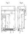
- the radio telephone 40 (see FIGS. 3 and 4) which can be detachably fastened with the holding device 10 consists of a cuboid base part 41 with a recess 42 on the top 43 and a handset 44 (FIG. 4) which are placed in the recess 42 can.
- the angled part 12 of the holding device 10 is designed as a hollow body and, as shown in FIG. 2, contains a clamping mechanism 50 which consists of a two-armed pivoting lever 52 which can be pivoted about a shaft 51 and a clamping lever 53 which is pivotably connected to the pivoting lever 52.
- a free end 54 of the pivot lever 52 protrudes from a first opening 55 and the clamping lever 53 min its free end 56 from a second opening 57.
- the free end 56 of the clamping lever 53 has a clamping piece 58 on its side facing the lower part 11, which is preferably spherical.
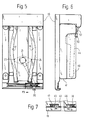
- the base part 41 of the radio telephone 40 to be fastened is placed on the holding device 10 fastened to the wall 35 with the screws 34, the parallel legs 17, 18 (FIGS. 1 and 5) engaging in the parallel grooves 45, 46 of the base part 41.
- the clamping device 50 (FIG. 2) takes its basic position - cf. Solid lines in Fig. 2 - a, in which the free end 54 of the pivot lever 52 from the protrudes first opening 55. If the radio telephone is then pushed in the direction of the arrow P2 (FIG. 3), it moves the swivel lever 52 with its front end face into the position indicated by dashed lines in FIG.
- the base part 41 of the radio telephone 40 comes under the projecting part 36 of the angled part 12 (cf. FIG. 4).
- the extension 30 of the slide valve 28 is then pushed in the direction of arrow P1 until it assumes the clamping position shown in FIG. 5.
- the lever arm 25 is pivoted in such a way that the flats 23 of the clamping lever 22 press the parallel legs 17, 18 of the holding device 10 outwards, until the clamping part 22 snaps into a position in which the flats are approximately parallel to the Legs 17 and 18 stand. This forms a latching position in which the base part 41 of the radio telephone 40 is clamped on the lower part 11; see. 5 and 7.
- the extension 30 (FIG. 5) is moved in the direction of the arrow P3 until it again assumes the position shown in FIG. 1. Then the radio telephone 40 can be conveniently pulled out of the holding device 10 because the clamping lever 53 yields somewhat due to its elasticity.
- a spring element (not shown in the drawing) in the angled part 12 ensures that the clamping device 50 returns to the basic position shown by solid lines in FIG. 2.
Landscapes
- Engineering & Computer Science (AREA)
- General Engineering & Computer Science (AREA)
- Mechanical Engineering (AREA)
- Signal Processing (AREA)
- Telephone Set Structure (AREA)
- Fittings On The Vehicle Exterior For Carrying Loads, And Devices For Holding Or Mounting Articles (AREA)
Claims (6)
- Dispositif de fixation pour un appareil électrique devant être fixé sur une paroi, ce dispositif de fixation comportant une partie inférieure avec des moyens de fixation mobiles, dispositif caractérisé en ce que les moyens de fixation sont constitués par un levier d'enclenchement (21) susceptible d'être déplacé en rotation manuellement, et par deux branches parallèles (17, 18) d'une pièce de pression élastique (15), en ce que ces branches (17, 18) viennent en prise dans des gorges parallèles (45, 46) sur le côté inférieur de l'appareil électrique (40), et en ce qu'une partie de serrage (22) du levier d'enclenchement (21) pousse les branches (17, 18) en les écartant l'une de l'autre lorsque le levier d'enclenchement (21) est amené en rotation dans la position de serrage.
- Dispositif de fixation selon la revendication 1, caractérisé en ce que la pièce de pression élastique (15) est une partie constitutive de la partie inférieure (11) du dispositif de fixation (10) constitué d'une matière synthétique.
- Dispositif de fixation selon la revendication 1 ou 2, caractérisé en ce que le levier d'enclenchement (21) est constitué par la partie de serrage (22) et par un bras de levier (25) assemblé avec elle, dont l'extrémité libre (26) est montée dans un curseur (28) susceptible d'être déplacé, dans les moyens de guidage (31) de la partie inférieure (11), d'une position de base vers une position de serrage et inversement.
- Dispositif de fixation selon l'une des revendications 1 à 3, caractérisé en ce que la partie de serrage (22) comporte, sur ses côtés opposés, respectivement un aplatissement (23, 24) qui, en combinaison avec les branches parallèles (17, 18) de la pièce de pression (15), forme un moyen d'enclenchement.
- Dispositif de fixation selon l'une des revendications 3 ou 4, caractérisé en ce que ce dispositif de fixation (10) comporte, à son extrémité opposée au curseur (28), une partie coudée (12) qui comprend un mécanisme de serrage (50) pour fixer de façon amovible un dispositif (44) déposé sur l'appareil électrique (40).
- Dispositif de fixation selon la revendication 5, caractérisé en ce que le mécanisme de serrage (50) est constitué par un levier oscillant à deux bras (52) et par un levier de serrage (53) articulé avec lui.
Applications Claiming Priority (2)
| Application Number | Priority Date | Filing Date | Title |
|---|---|---|---|
| DE4235041 | 1992-10-17 | ||
| DE4235041A DE4235041A1 (de) | 1992-10-17 | 1992-10-17 | Haltevorrichtung für ein elektrisches Gerät |
Publications (2)
| Publication Number | Publication Date |
|---|---|
| EP0593934A1 EP0593934A1 (fr) | 1994-04-27 |
| EP0593934B1 true EP0593934B1 (fr) | 1996-04-24 |
Family
ID=6470697
Family Applications (1)
| Application Number | Title | Priority Date | Filing Date |
|---|---|---|---|
| EP93115405A Expired - Lifetime EP0593934B1 (fr) | 1992-10-17 | 1993-09-24 | Dispositif de fixation pour un appareil électrique |
Country Status (2)
| Country | Link |
|---|---|
| EP (1) | EP0593934B1 (fr) |
| DE (2) | DE4235041A1 (fr) |
Families Citing this family (3)
| Publication number | Priority date | Publication date | Assignee | Title |
|---|---|---|---|---|
| DE19509685A1 (de) * | 1995-03-07 | 1996-09-12 | Deutsche Telephonwerk Kabel | Kommunikationsendgerät für Bündelfunk |
| DE19624161C2 (de) * | 1996-06-18 | 2001-06-07 | Gerhard Mueller | Halteanordnung |
| CN114776997B (zh) * | 2022-03-23 | 2023-10-10 | 呼伦贝尔安泰热电有限责任公司海拉尔热电厂 | 一种电厂热控用热控仪表安装装置 |
Family Cites Families (5)
| Publication number | Priority date | Publication date | Assignee | Title |
|---|---|---|---|---|
| US4986503A (en) * | 1988-11-25 | 1991-01-22 | Kabat Thomas W | Mounting device |
| DE8901019U1 (de) * | 1989-01-31 | 1989-03-09 | Robert Bosch Gmbh, 7000 Stuttgart | Haltevorrichtung für ein an einer Wand lösbar zu befestigendes Funkgerät |
| US5038253A (en) * | 1990-05-14 | 1991-08-06 | Motorola, Inc. | Transceiver mounting assembly having integrally formed lock |
| US5169097A (en) * | 1990-11-27 | 1992-12-08 | Oki Electric Industry Co., Ltd. | Apparatus and method for supporting an accessory unit within an automobile storage area |
| DE4107996C2 (de) * | 1991-03-13 | 1996-02-15 | Aeg Mobile Communication | Schwenkbares Gehäuse mit elektrischer Steckverbindung zur zeitweiligen Halterung von tragbaren Funkgeräten |
-
1992
- 1992-10-17 DE DE4235041A patent/DE4235041A1/de not_active Withdrawn
-
1993
- 1993-09-24 DE DE59302350T patent/DE59302350D1/de not_active Expired - Fee Related
- 1993-09-24 EP EP93115405A patent/EP0593934B1/fr not_active Expired - Lifetime
Also Published As
| Publication number | Publication date |
|---|---|
| EP0593934A1 (fr) | 1994-04-27 |
| DE4235041A1 (de) | 1994-04-21 |
| DE59302350D1 (de) | 1996-05-30 |
Similar Documents
| Publication | Publication Date | Title |
|---|---|---|
| EP0198099A1 (fr) | Contacteur en particulier contacteur auxiliaire ou contacteur de moteur | |
| DE2511392A1 (de) | Schwingschleifer mit staubabsaugung | |
| EP0593934B1 (fr) | Dispositif de fixation pour un appareil électrique | |
| EP0611931B1 (fr) | Conteneur, en particulier en forme de tiroir | |
| EP0673095A1 (fr) | Commutateur électrique | |
| DE29617895U1 (de) | Versorgungsbalken für die Intensivpflege | |
| DE2448111C3 (de) | Anordnung zum Anschluß elektrischer Leitungen an ein elektrisches Gerät | |
| DE10014130A1 (de) | Elektrischer Verbinder für eine flexible Leiterbahn | |
| DE2615242A1 (de) | Schnellmontagesockel | |
| DE2636632A1 (de) | Elektrischer schalter | |
| CH689908A5 (de) | Vorrichtung zur lösbaren Schnellbefestigung eines elektrischen Reiheneinbaugerätes, insbesondere eines Leitungsschutzschalters. | |
| DE69701734T2 (de) | Steuervorrichtung oder signalisierungvorrichtung wie eine drucktaste | |
| DE2607186A1 (de) | Drucktastenschalter mit einem beweglichen, einrastbaren schieber | |
| DE2608193C3 (de) | Anordnung zur Befestigung elektrischer Baugruppen | |
| DE29500046U1 (de) | Klemmvorrichtung, insbesondere an Operationstischen | |
| WO2002046515A1 (fr) | Adaptateur destine a la fixation de regulateurs de niveau d'eau | |
| DE3205575C2 (de) | Bedienungseinheit für ein elektrisches Gerät | |
| DE19848496C2 (de) | Koppelvorrichtung für eine Bürotischanordnung | |
| DE3326934A1 (de) | Aufnahmevorrichtung und geraeteeinsatz fuer die nachrichtentechnik | |
| DE3340659A1 (de) | Montagesockel fuer ein befehls- oder meldegeraet | |
| AT284938B (de) | Anordnumg zur Befestigung elektrischer Installationsgeräte | |
| DE2424717A1 (de) | Tuchhalter | |
| AT501584B1 (de) | Anschluss- oder geräteadapter | |
| DE3030161A1 (de) | Leuchtengehaeuse mit mindestens einer hakenfoermigen feder zur loesbaren halterung von einsaetzen | |
| DE2422805C2 (de) | Gehäuse für Fernsehempfangsgeräte mit einer Befestigungsvorrichtung für Schaltungsplatten |
Legal Events
| Date | Code | Title | Description |
|---|---|---|---|
| PUAI | Public reference made under article 153(3) epc to a published international application that has entered the european phase |
Free format text: ORIGINAL CODE: 0009012 |
|
| AK | Designated contracting states |
Kind code of ref document: A1 Designated state(s): CH DE ES FR IT LI SE |
|
| 17P | Request for examination filed |
Effective date: 19941027 |
|
| 17Q | First examination report despatched |
Effective date: 19950620 |
|
| GRAA | (expected) grant |
Free format text: ORIGINAL CODE: 0009210 |
|
| AK | Designated contracting states |
Kind code of ref document: B1 Designated state(s): CH DE ES FR IT LI SE |
|
| PG25 | Lapsed in a contracting state [announced via postgrant information from national office to epo] |
Ref country code: IT Free format text: LAPSE BECAUSE OF FAILURE TO SUBMIT A TRANSLATION OF THE DESCRIPTION OR TO PAY THE FEE WITHIN THE PRESCRIBED TIME-LIMIT;WARNING: LAPSES OF ITALIAN PATENTS WITH EFFECTIVE DATE BEFORE 2007 MAY HAVE OCCURRED AT ANY TIME BEFORE 2007. THE CORRECT EFFECTIVE DATE MAY BE DIFFERENT FROM THE ONE RECORDED. Effective date: 19960424 Ref country code: ES Free format text: THE PATENT HAS BEEN ANNULLED BY A DECISION OF A NATIONAL AUTHORITY Effective date: 19960424 |
|
| REG | Reference to a national code |
Ref country code: CH Ref legal event code: NV Representative=s name: SCINTILLA AG, DIREKTION |
|
| ET | Fr: translation filed | ||
| REF | Corresponds to: |
Ref document number: 59302350 Country of ref document: DE Date of ref document: 19960530 |
|
| PG25 | Lapsed in a contracting state [announced via postgrant information from national office to epo] |
Ref country code: SE Effective date: 19960724 |
|
| PG25 | Lapsed in a contracting state [announced via postgrant information from national office to epo] |
Ref country code: LI Effective date: 19960930 Ref country code: CH Effective date: 19960930 |
|
| PLBE | No opposition filed within time limit |
Free format text: ORIGINAL CODE: 0009261 |
|
| 26N | No opposition filed | ||
| REG | Reference to a national code |
Ref country code: CH Ref legal event code: PL |
|
| PG25 | Lapsed in a contracting state [announced via postgrant information from national office to epo] |
Ref country code: DE Effective date: 19970603 |
|
| PG25 | Lapsed in a contracting state [announced via postgrant information from national office to epo] |
Ref country code: FR Effective date: 19970630 |
|
| REG | Reference to a national code |
Ref country code: FR Ref legal event code: ST |
|
| REG | Reference to a national code |
Ref country code: FR Ref legal event code: ST |