EP0593941A1 - Tête d'usinage laser et dispositif supplémentaire pour une machine-outil à commande numérique - Google Patents
Tête d'usinage laser et dispositif supplémentaire pour une machine-outil à commande numérique Download PDFInfo
- Publication number
- EP0593941A1 EP0593941A1 EP93115505A EP93115505A EP0593941A1 EP 0593941 A1 EP0593941 A1 EP 0593941A1 EP 93115505 A EP93115505 A EP 93115505A EP 93115505 A EP93115505 A EP 93115505A EP 0593941 A1 EP0593941 A1 EP 0593941A1
- Authority
- EP
- European Patent Office
- Prior art keywords
- laser
- tool
- processing head
- laser processing
- head
- Prior art date
- Legal status (The legal status is an assumption and is not a legal conclusion. Google has not performed a legal analysis and makes no representation as to the accuracy of the status listed.)
- Granted
Links
Images

Classifications
-
- G—PHYSICS
- G05—CONTROLLING; REGULATING
- G05B—CONTROL OR REGULATING SYSTEMS IN GENERAL; FUNCTIONAL ELEMENTS OF SUCH SYSTEMS; MONITORING OR TESTING ARRANGEMENTS FOR SUCH SYSTEMS OR ELEMENTS
- G05B19/00—Program-control systems
- G05B19/02—Program-control systems electric
- G05B19/18—Numerical control [NC], i.e. automatically operating machines, in particular machine tools, e.g. in a manufacturing environment, so as to execute positioning, movement or co-ordinated operations by means of program data in numerical form
- G05B19/406—Numerical control [NC], i.e. automatically operating machines, in particular machine tools, e.g. in a manufacturing environment, so as to execute positioning, movement or co-ordinated operations by means of program data in numerical form characterised by monitoring or safety
-
- B—PERFORMING OPERATIONS; TRANSPORTING
- B23—MACHINE TOOLS; METAL-WORKING NOT OTHERWISE PROVIDED FOR
- B23B—TURNING; BORING
- B23B31/00—Chucks; Expansion mandrels; Adaptations thereof for remote control
- B23B31/006—Conical shanks of tools
-
- B—PERFORMING OPERATIONS; TRANSPORTING
- B23—MACHINE TOOLS; METAL-WORKING NOT OTHERWISE PROVIDED FOR
- B23K—SOLDERING OR UNSOLDERING; WELDING; CLADDING OR PLATING BY SOLDERING OR WELDING; CUTTING BY APPLYING HEAT LOCALLY, e.g. FLAME CUTTING; WORKING BY LASER BEAM
- B23K26/00—Working by laser beam, e.g. welding, cutting or boring
- B23K26/0093—Working by laser beam, e.g. welding, cutting or boring combined with mechanical machining or metal-working covered by other subclasses than B23K
-
- B—PERFORMING OPERATIONS; TRANSPORTING
- B23—MACHINE TOOLS; METAL-WORKING NOT OTHERWISE PROVIDED FOR
- B23K—SOLDERING OR UNSOLDERING; WELDING; CLADDING OR PLATING BY SOLDERING OR WELDING; CUTTING BY APPLYING HEAT LOCALLY, e.g. FLAME CUTTING; WORKING BY LASER BEAM
- B23K26/00—Working by laser beam, e.g. welding, cutting or boring
- B23K26/14—Working by laser beam, e.g. welding, cutting or boring using a fluid stream, e.g. a jet of gas, in conjunction with the laser beam; Nozzles therefor
- B23K26/1462—Nozzles; Features related to nozzles
- B23K26/1482—Detachable nozzles, e.g. exchangeable or provided with breakaway lines
-
- B—PERFORMING OPERATIONS; TRANSPORTING
- B23—MACHINE TOOLS; METAL-WORKING NOT OTHERWISE PROVIDED FOR
- B23P—METAL-WORKING NOT OTHERWISE PROVIDED FOR; COMBINED OPERATIONS; UNIVERSAL MACHINE TOOLS
- B23P23/00—Machines or arrangements of machines for performing specified combinations of different metal-working operations not covered by a single other subclass
- B23P23/02—Machine tools for performing different machining operations
-
- B—PERFORMING OPERATIONS; TRANSPORTING
- B23—MACHINE TOOLS; METAL-WORKING NOT OTHERWISE PROVIDED FOR
- B23Q—DETAILS, COMPONENTS, OR ACCESSORIES FOR MACHINE TOOLS, e.g. ARRANGEMENTS FOR COPYING OR CONTROLLING; MACHINE TOOLS IN GENERAL CHARACTERISED BY THE CONSTRUCTION OF PARTICULAR DETAILS OR COMPONENTS; COMBINATIONS OR ASSOCIATIONS OF METAL-WORKING MACHINES, NOT DIRECTED TO A PARTICULAR RESULT
- B23Q1/00—Members which are comprised in the general build-up of a form of machine, particularly relatively large fixed members
- B23Q1/0009—Energy-transferring means or control lines for movable machine parts; Control panels or boxes; Control parts
-
- B—PERFORMING OPERATIONS; TRANSPORTING
- B23—MACHINE TOOLS; METAL-WORKING NOT OTHERWISE PROVIDED FOR
- B23Q—DETAILS, COMPONENTS, OR ACCESSORIES FOR MACHINE TOOLS, e.g. ARRANGEMENTS FOR COPYING OR CONTROLLING; MACHINE TOOLS IN GENERAL CHARACTERISED BY THE CONSTRUCTION OF PARTICULAR DETAILS OR COMPONENTS; COMBINATIONS OR ASSOCIATIONS OF METAL-WORKING MACHINES, NOT DIRECTED TO A PARTICULAR RESULT
- B23Q1/00—Members which are comprised in the general build-up of a form of machine, particularly relatively large fixed members
- B23Q1/25—Movable or adjustable work or tool supports
- B23Q1/44—Movable or adjustable work or tool supports using particular mechanisms
- B23Q1/50—Movable or adjustable work or tool supports using particular mechanisms with rotating pairs only, the rotating pairs being the first two elements of the mechanism
- B23Q1/54—Movable or adjustable work or tool supports using particular mechanisms with rotating pairs only, the rotating pairs being the first two elements of the mechanism two rotating pairs only
- B23Q1/545—Movable or adjustable work or tool supports using particular mechanisms with rotating pairs only, the rotating pairs being the first two elements of the mechanism two rotating pairs only comprising spherical surfaces
- B23Q1/5462—Movable or adjustable work or tool supports using particular mechanisms with rotating pairs only, the rotating pairs being the first two elements of the mechanism two rotating pairs only comprising spherical surfaces with one supplementary sliding pair
-
- B—PERFORMING OPERATIONS; TRANSPORTING
- B23—MACHINE TOOLS; METAL-WORKING NOT OTHERWISE PROVIDED FOR
- B23Q—DETAILS, COMPONENTS, OR ACCESSORIES FOR MACHINE TOOLS, e.g. ARRANGEMENTS FOR COPYING OR CONTROLLING; MACHINE TOOLS IN GENERAL CHARACTERISED BY THE CONSTRUCTION OF PARTICULAR DETAILS OR COMPONENTS; COMBINATIONS OR ASSOCIATIONS OF METAL-WORKING MACHINES, NOT DIRECTED TO A PARTICULAR RESULT
- B23Q11/00—Accessories fitted to machine tools for keeping tools or parts of the machine in good working condition or for cooling work; Safety devices specially combined with or arranged in, or specially adapted for use in connection with, machine tools
-
- B—PERFORMING OPERATIONS; TRANSPORTING
- B23—MACHINE TOOLS; METAL-WORKING NOT OTHERWISE PROVIDED FOR
- B23Q—DETAILS, COMPONENTS, OR ACCESSORIES FOR MACHINE TOOLS, e.g. ARRANGEMENTS FOR COPYING OR CONTROLLING; MACHINE TOOLS IN GENERAL CHARACTERISED BY THE CONSTRUCTION OF PARTICULAR DETAILS OR COMPONENTS; COMBINATIONS OR ASSOCIATIONS OF METAL-WORKING MACHINES, NOT DIRECTED TO A PARTICULAR RESULT
- B23Q17/00—Arrangements for observing, indicating or measuring on machine tools
- B23Q17/006—Arrangements for observing, indicating or measuring on machine tools for indicating the presence of a work or tool in its holder
Definitions
- the invention relates to a laser processing head for a numerically controlled machine tool, which, for the purpose of replacement with a mechanical processing tool, can be coupled to the tool holder of the machine tool, corresponds to the tool shaft of the mechanical processing tool, and the coaxial arrangement of the laser head to the axis of the mechanical processing tool permitting tool shank is provided.
- the invention further relates to an additional device for a numerically controlled machine tool with such a laser processing head that can be coupled to the tool holder of the machine tool.
- EP 0158866 B1 discloses a numerically controlled machine tool for optionally machining a workpiece with a mechanical machining tool or with a laser cutting device.
- the mechanical processing tool for example a punching tool
- the laser processing head are each provided with an identically designed shaft with which they are inserted into the tool holder of the machine tool. If the laser processing head is inserted into the tool holder, the geometric axis of the laser head corresponds to the geometric axis of the mechanical processing tool. As a result, the same program can be used in such a machine regardless of the tool.
- the interchangeable laser processing head is designed as a rigid device. It consists of a cylindrical hollow body and comprises a nozzle directed against the workpiece and a lens holder with a lens through which the laser beams are focused on the workpiece.
- the laser beams are deflected in the axial direction via a deflection mirror arranged outside the laser head and directed through the cylindrical hollow body onto the lens.
- a device of the type mentioned at the outset is also known, in which the laser radiation is transmitted from the laser to the laser processing head by means of a light guide cable (JP 3-165983 A, Patents Abstracts of Japan, 1991, Vol.15 / No.404, Sec.M-1168)
- the invention is based on the object of further developing a machine tool of the type mentioned at the outset such that possible displacements of the geometric axis of the laser beam and / or angular deflections of the laser beam which cannot always be avoided due to misalignments in the mechanical and optical system of such a machine, can be corrected at any time in a relatively simple manner.
- this object is achieved in that the laser machining head from a containing the tool shank Part and a part containing the laser optics, the spatial position of each other is adjustable.
- the tool shank with which the laser machining head is inserted into the tool holder can expediently be a tool shank with the standardized dimensions of a tool shank for a cutting tool, so that the laser tool according to the invention Machining head can be clamped in a standard tool holder of a machine tool.
- the part containing the tool shank and the part of the laser machining head containing the laser optics are connected to one another via a self-aligning bearing, the angular position of the two parts relative to one another being adjustable by means of adjusting screws.
- the bearing shell of the self-aligning bearing arranged in the part having the tool shank is expediently adjusted by adjusting screws perpendicular to the axial direction of the tool holder of the machine tool adjustable.
- a further advantageous embodiment of the invention consists in that the laser beams are transmitted from a stationary laser to the laser processing head via a light guide cable which is coupled to the laser processing head laterally at a right angle to the direction of the laser beam emerging from the laser processing head and that for deflecting the laser beams in the axial direction of the tool carrier, an optical system is arranged in the laser machining head.
- a retrofit kit for a numerically controlled machine tool which has a laser machining head provided with a tool shaft that can be coupled to the tool holder of the machine tool, comprises a tool box accommodating the laser processing head in the waiting position and a control circuit controlling the laser and the machine tool, the laser processing head consisting of a part containing the tool shaft and a part containing the laser optics, the spatial position of which can be adjusted relative to one another such that the laser -Processing head has a control switch for controlling the clamping and a position sensor for detecting the clamping position, and that the control switch and / or the position sensor forms a part of the control circuit safety circuit for switching on d drive it laser.
- the machine tool 1 is, for example, a numerically controlled milling machine in which a cross slide is provided with a tool carrier which has a tool spindle arranged concentrically to the tool carrier and driven by an electric motor.
- the tool spindle is coupled to the rotating milling tool as soon as the milling tool is fastened in the tool carrier.
- the rotatable tool spindle can be used directly as a tool carrier serve.
- the machine tool 1 can also be, for example, a numerically controlled lathe, in which the tool is arranged on a cross slide and is displaced longitudinally and transversely to the axis of rotation of the clamped and rotated workpiece.
- both the XY travel control of the cross slide and the control of the drive motor for are carried out with the aid of the numerical control, which is integrated in the schematic representation in the machine tool 1 the tool spindle and the control of the other drive motors, for example the drive motor for the coolant during mechanical processing and the drive motor of the fan supplying the working gas when using the laser processing head.
- the tool carrier of the milling machine is equipped with a standardized clamping coupling, for example for a SK40 steep taper. To this extent, it is preferably a conventional machine tool, such as is used for the machining of workpieces and is available on the market.
- the tool holder of the machine tool 1 is clamped with the laser machining head 2 provided with a tool shaft corresponding to the coupling piece of the tool holder, the construction of which will be described in detail later.
- a flexible light guide cable 3 is coupled to the laser processing head 2, through which the laser beams generated in the laser 4 can be supplied to the laser processing head 2.
- the laser 4 can be arranged at a suitable location on the machine tool 1 in a stationary manner.
- a safety device which comprises a tool box 6 and is connected to the laser control 5.
- the tool box 6 serves to receive the laser processing head 2 when it is not in use and is not clamped to the tool carrier.
- the top of the tool box is provided with a recess adapted to the laser processing head 2, into which the laser head 2 is inserted.
- One or more safety switches 13 are arranged in the tool box 6 and are actuated by the laser head 2 when it is in the tool box.
- the safety device also includes a control switch 9 arranged in the laser head 2. This control switch 9 detects whether the laser head 2 is properly clamped in the tool holder.
- the safety device includes a position sensor 10, which is activated only when the part of the laser head 2 which emits the laser beam is exactly aligned in the desired working position, in which the operator and the surroundings of the machine are protected by suitable safety precautions.
- the safety circuit fulfilling these criteria ensures that, on the one hand, the operator of the machine and the working environment are not endangered by the laser beam, since the laser 4 cannot be switched on as long as the laser head 2 is not firmly clamped and the laser beam is not has the desired direction, that is to say is not aligned exactly downwards in a milling machine. On the other hand, it is additionally ensured that the work spindle, and thus the laser head 2, is not set in rotation in its working position.
- control signals coming from this safety circuit can expediently perform other additional functions. This means that these control signals can be used in addition to switching the laser and the drive motor of the work spindle on and off can still be used to switch the drive motor of the coolant pump on and off and to switch the drive motor of the gas pump delivering the working gas for the laser head on and off. In other words, these control signals coming from the safety circuit can also be used to switch over other devices of the machine tool, the switchover of which is necessary or expedient when changing from mechanical operation of the machine to laser operation and vice versa.
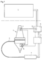
- the structure of the laser processing head 2 is shown in detail in FIG. 2. It comprises two parts which are movably connected to one another to a certain extent, namely the actual tool shaft 12 and a lower part 14 which contains the laser optics.
- a slide 16 loaded with a plate spring 15, in which the clamping receiver 17 provided with an annular flute is seated.
- the self-aligning bearing for mounting the lower part 14 which has the laser optics.
- the self-aligning bearing comprises a bearing shell 19 in the form of a hollow cylindrical body, the upper bearing surface 20 of which is hollow.
- the bearing shell 19 rests on an externally threaded washer 21 which is screwed into a corresponding threaded hole in the tool shank.
- the bearing shell 19 can be adjusted so that the laser beam emerging from the laser head runs coaxially to the spindle axis of rotation of the machine tool.
- the lower part 14 of the laser head 2 is pivoted in all directions.
- the angular position of the lower part 14, and thus the precise alignment of the laser beam, can be adjusted using three screws 28, for example.
- the light guide cable coming from the laser is connected laterally to the lower part 14 of the laser head.
- a connection socket 29 is provided on the side, into which the plug of the light guide cable is inserted.
- the laser beams strike the deflecting mirror 30 arranged in the lower part 14 and are deflected by the latter onto a lens or a lens system 31, through which the laser beams are focused.
- the laser head is provided with a cutting nozzle 32, through which the laser beam on the one hand and a working gas on the other hand exit.
- the connection for the working gas is not shown in the drawing.
- a welding attachment can also be used.
Landscapes
- Engineering & Computer Science (AREA)
- Mechanical Engineering (AREA)
- Physics & Mathematics (AREA)
- Optics & Photonics (AREA)
- Plasma & Fusion (AREA)
- General Physics & Mathematics (AREA)
- Automation & Control Theory (AREA)
- Manufacturing & Machinery (AREA)
- Human Computer Interaction (AREA)
- Laser Beam Processing (AREA)
- Cutting Tools, Boring Holders, And Turrets (AREA)
- Automatic Tool Replacement In Machine Tools (AREA)
- Jigs For Machine Tools (AREA)
- Multi-Process Working Machines And Systems (AREA)
Applications Claiming Priority (2)
| Application Number | Priority Date | Filing Date | Title |
|---|---|---|---|
| DE4235592A DE4235592C1 (de) | 1992-10-22 | 1992-10-22 | Laser-Bearbeitungskopf und Zusatzeinrichtung für eine numerisch gesteuerte Werkzeugmaschine |
| DE4235592 | 1992-10-22 |
Publications (2)
| Publication Number | Publication Date |
|---|---|
| EP0593941A1 true EP0593941A1 (fr) | 1994-04-27 |
| EP0593941B1 EP0593941B1 (fr) | 1995-03-15 |
Family
ID=6471037
Family Applications (1)
| Application Number | Title | Priority Date | Filing Date |
|---|---|---|---|
| EP93115505A Expired - Lifetime EP0593941B1 (fr) | 1992-10-22 | 1993-09-25 | Tête d'usinage laser et dispositif supplémentaire pour une machine-outil à commande numérique |
Country Status (5)
| Country | Link |
|---|---|
| US (1) | US5508490A (fr) |
| EP (1) | EP0593941B1 (fr) |
| JP (1) | JPH06339785A (fr) |
| AT (1) | ATE119816T1 (fr) |
| DE (2) | DE4235592C1 (fr) |
Cited By (2)
| Publication number | Priority date | Publication date | Assignee | Title |
|---|---|---|---|---|
| US5728051A (en) * | 1996-02-27 | 1998-03-17 | Chi; Stephen | Massager having removable massage elements |
| CN105612026A (zh) * | 2013-09-13 | 2016-05-25 | 德马吉森股份公司 | 数控机床 |
Families Citing this family (29)
| Publication number | Priority date | Publication date | Assignee | Title |
|---|---|---|---|---|
| IT1277080B1 (it) * | 1995-12-14 | 1997-11-04 | Salvagnini Italia Spa | Testa di focalizzazione di un fascio laser dotata di una lente di focalizzazione per una macchina di lavorazione di pezzi metallici |
| DE19853365A1 (de) * | 1998-11-19 | 2000-05-25 | Schuler Pressen Gmbh & Co | Verfahren und Vorrichtung zum Umformen |
| AU5168000A (en) * | 1999-05-26 | 2000-12-12 | Ii-Vi Incorporated | Improved optical contacting method and apparatus |
| US6658316B1 (en) | 1999-12-30 | 2003-12-02 | Abb Technology Ag | Parametric programming of robots and automated machines for manufacturing electrical enclosures |
| US6643561B1 (en) | 1999-12-30 | 2003-11-04 | Abb Technology Ag | Parametric programming of laser cutting system |
| DE10060176B4 (de) * | 2000-12-04 | 2008-06-19 | Precitec Kg | Laserbearbeitungskopf |
| US11228735B2 (en) * | 2003-01-14 | 2022-01-18 | Tseng-Lu Chien | LED or laser project light has more than 1 functions |
| JP4390627B2 (ja) * | 2004-05-28 | 2009-12-24 | ヤマザキマザック株式会社 | レーザ焼き入れ工具 |
| US20060006157A1 (en) * | 2004-07-09 | 2006-01-12 | Ingersoll Machine Tools, Inc. | Method and apparatus for repairing or building up surfaces on a workpiece while the workpiece is mounted on a machine tool |
| ATE416878T1 (de) * | 2004-08-06 | 2008-12-15 | Trumpf Werkzeugmaschinen Gmbh | Laserbearbeitungskopf |
| JP2006281390A (ja) * | 2005-04-01 | 2006-10-19 | Jtekt Corp | 複合加工機及びこれを用いたワークの加工方法 |
| DE102006003682A1 (de) * | 2006-01-24 | 2007-07-26 | Jenoptik Automatisierungstechnik Gmbh | Kombinierte Vorrichtung zur Materialbearbeitung mit einem Fräser und einem Laser |
| JP2007313515A (ja) * | 2006-05-23 | 2007-12-06 | Jtekt Corp | 複合加工機及びこれを使用した加工方法 |
| DE102008056278A1 (de) * | 2008-10-25 | 2010-04-29 | Kjellberg Finsterwalde Plasma Und Maschinen Gmbh | System zur thermischen Bearbeitung von Werkstücken |
| DE102008055971A1 (de) * | 2008-11-05 | 2010-05-06 | Komet Group Gmbh | Bearbeitungszentrum mit Drehübertrager für elektrische Energie |
| US11476626B2 (en) | 2008-11-12 | 2022-10-18 | Aaron Chien | DC powered remote control LED light-bar assembly |
| US10509304B2 (en) | 2008-11-12 | 2019-12-17 | Tseng-Lu Chien | LED projection light has features |
| US20100271010A1 (en) * | 2009-04-27 | 2010-10-28 | Visible Assets, Inc | Tool Sensor, System and Method |
| CN102166685B (zh) * | 2011-04-27 | 2013-12-25 | 华中科技大学 | 一种三坐标振镜扫描式激光加工头 |
| JP6139918B2 (ja) * | 2013-03-06 | 2017-05-31 | 株式会社アマダホールディングス | レーザ加工機 |
| US20140283987A1 (en) * | 2013-03-19 | 2014-09-25 | Systems And Materials Research Corporation | Method and apparatus to apply a fill material to a substrate |
| EP3107680A4 (fr) * | 2014-02-20 | 2018-01-03 | Dmg Mori Seiki Advanced Solutions Inc. | Tête de traitement pour un centre de fabrication additif/soustractif hybride |
| CN105773303A (zh) * | 2016-04-12 | 2016-07-20 | 莱芜钢铁集团有限公司 | 机床直线升降精度矫正用辅助组件及方法 |
| CN105643366A (zh) * | 2016-04-12 | 2016-06-08 | 莱芜钢铁集团有限公司 | 机床的水平导轨的水平度矫正用辅助组件及方法 |
| US10464165B2 (en) * | 2016-08-02 | 2019-11-05 | Nakamura-Tome Precision Industry Co., Ltd. | Combined machining apparatus having a laser machining head |
| CA3076196A1 (fr) * | 2017-09-18 | 2019-03-21 | Robert Bosch Tool Corporation | Procede destine a assurer une fonctionnalite critique de securite pour une machine a alimentation electrique |
| US10926355B2 (en) | 2019-02-05 | 2021-02-23 | Dukane Ias, Llc | Systems and methods for laser-welding tubular components using a single, fixed optical reflector with multiple reflecting surfaces |
| US11819940B2 (en) | 2019-02-05 | 2023-11-21 | Dukane Ias, Llc | Systems and methods for laser-welding a workpiece with a laser beam that reaches inaccessible areas of the workpiece using multiple reflecting parts |
| US11931823B2 (en) | 2019-02-05 | 2024-03-19 | Dukane Ias, Llc | Systems and methods for laser-welding a workpiece with a laser beam that reaches inaccessible areas of the workpiece using multiple reflecting parts |
Citations (5)
| Publication number | Priority date | Publication date | Assignee | Title |
|---|---|---|---|---|
| JPS56168918A (en) * | 1980-05-31 | 1981-12-25 | Amada Co Ltd | Laser cutter |
| EP0158866B1 (fr) * | 1984-03-24 | 1989-06-28 | Trumpf GmbH & Co | Machine-outil pour le travail mécanique et thermique d'une pièce de travail |
| JPH03165983A (ja) * | 1989-11-22 | 1991-07-17 | Amada Co Ltd | レーザ・パンチ複合加工機 |
| JPH04197589A (ja) * | 1990-11-28 | 1992-07-17 | Amada Co Ltd | レーザパンチプレス、当該パンチプレスに用いるレーザ加工ヘッドユニット、レーザ加工ヘッドユニットとレーザ発振器とを接続する接続装置及びレーザ光路調整時に用いられるビーム検出装置 |
| WO1992016334A1 (fr) * | 1991-03-15 | 1992-10-01 | Fanuc Ltd | Machine-outil combinee fonctionnant au laser |
Family Cites Families (11)
| Publication number | Priority date | Publication date | Assignee | Title |
|---|---|---|---|---|
| FR2556262B1 (fr) * | 1983-12-09 | 1987-02-20 | Ressencourt Hubert | La presente invention concerne un centre de faconnage de materiaux en feuilles a commande numerique |
| EP0262198B1 (fr) * | 1986-03-25 | 1992-03-25 | Laser Lab Limited | Dispositif a tete de travail |
| JPS63104794A (ja) * | 1986-10-21 | 1988-05-10 | Mitsubishi Electric Corp | レ−ザ加工機 |
| DE8816726U1 (de) * | 1988-04-26 | 1990-05-10 | Carl Baasel Lasertechnik GmbH, 8130 Starnberg | Laserdüsenkopf |
| JPH01321089A (ja) * | 1988-06-22 | 1989-12-27 | Mitsubishi Electric Corp | レーザ加工機用加工ヘッド |
| JPH02224887A (ja) * | 1989-02-28 | 1990-09-06 | Komatsu Ltd | レーザ加工装置 |
| DE3939812C2 (de) * | 1989-12-01 | 1993-11-11 | Deutsche Aerospace | Laserlötsystem für SMD-Elemente |
| JPH04111989A (ja) * | 1990-08-31 | 1992-04-13 | Mitsubishi Electric Corp | レーザ加工装置 |
| WO1992016314A1 (fr) * | 1991-03-12 | 1992-10-01 | Haakansson Lars | Dispositif de nettoyage d'objets, notamment metalliques |
| DE4143414C2 (de) * | 1991-09-03 | 1996-06-20 | Precitec Gmbh | Werkzeugkopf mit automatisch verstellbarer Fokussierungsoptik |
| JP2804206B2 (ja) * | 1992-09-22 | 1998-09-24 | 三菱電機株式会社 | レーザ加工ヘッド |
-
1992
- 1992-10-22 DE DE4235592A patent/DE4235592C1/de not_active Expired - Fee Related
-
1993
- 1993-09-25 EP EP93115505A patent/EP0593941B1/fr not_active Expired - Lifetime
- 1993-09-25 DE DE59300107T patent/DE59300107D1/de not_active Expired - Fee Related
- 1993-09-25 AT AT93115505T patent/ATE119816T1/de not_active IP Right Cessation
- 1993-10-14 US US08/136,510 patent/US5508490A/en not_active Expired - Fee Related
- 1993-10-19 JP JP5260724A patent/JPH06339785A/ja active Pending
Patent Citations (5)
| Publication number | Priority date | Publication date | Assignee | Title |
|---|---|---|---|---|
| JPS56168918A (en) * | 1980-05-31 | 1981-12-25 | Amada Co Ltd | Laser cutter |
| EP0158866B1 (fr) * | 1984-03-24 | 1989-06-28 | Trumpf GmbH & Co | Machine-outil pour le travail mécanique et thermique d'une pièce de travail |
| JPH03165983A (ja) * | 1989-11-22 | 1991-07-17 | Amada Co Ltd | レーザ・パンチ複合加工機 |
| JPH04197589A (ja) * | 1990-11-28 | 1992-07-17 | Amada Co Ltd | レーザパンチプレス、当該パンチプレスに用いるレーザ加工ヘッドユニット、レーザ加工ヘッドユニットとレーザ発振器とを接続する接続装置及びレーザ光路調整時に用いられるビーム検出装置 |
| WO1992016334A1 (fr) * | 1991-03-15 | 1992-10-01 | Fanuc Ltd | Machine-outil combinee fonctionnant au laser |
Non-Patent Citations (3)
| Title |
|---|
| PATENT ABSTRACTS OF JAPAN vol. 006, no. 056 (M - 121) 13 April 1982 (1982-04-13) * |
| PATENT ABSTRACTS OF JAPAN vol. 015, no. 404 (M - 1168) 15 October 1991 (1991-10-15) * |
| PATENT ABSTRACTS OF JAPAN vol. 016, no. 529 (M - 1332) 29 October 1992 (1992-10-29) * |
Cited By (3)
| Publication number | Priority date | Publication date | Assignee | Title |
|---|---|---|---|---|
| US5728051A (en) * | 1996-02-27 | 1998-03-17 | Chi; Stephen | Massager having removable massage elements |
| CN105612026A (zh) * | 2013-09-13 | 2016-05-25 | 德马吉森股份公司 | 数控机床 |
| CN105612026B (zh) * | 2013-09-13 | 2019-08-06 | 德马吉森股份公司 | 数控机床 |
Also Published As
| Publication number | Publication date |
|---|---|
| ATE119816T1 (de) | 1995-04-15 |
| US5508490A (en) | 1996-04-16 |
| DE59300107D1 (de) | 1995-04-20 |
| DE4235592C1 (de) | 1994-01-27 |
| EP0593941B1 (fr) | 1995-03-15 |
| JPH06339785A (ja) | 1994-12-13 |
Similar Documents
| Publication | Publication Date | Title |
|---|---|---|
| EP0593941B1 (fr) | Tête d'usinage laser et dispositif supplémentaire pour une machine-outil à commande numérique | |
| DE60217629T2 (de) | Laser-Positionier-System für Maschine zum Bearbeiten von Löchern | |
| DE102016118189B4 (de) | Verfahren und Laserbearbeitungsmaschine zum Laserschweißen eines ersten und eines zweiten Werkstückabschnitts | |
| EP1034875B1 (fr) | Machine-outil pour l'usinage avec outils de coupe et laser | |
| DE102018005097B4 (de) | Faserauswahlvorrichtung und laservorrichtung | |
| DE2640257C2 (fr) | ||
| DE2933700A1 (de) | Werkzeugmaschine mit schmelzschneideinrichtung | |
| EP0707920A2 (fr) | Tête d'usinage au laser compacte pour l'usinage de matériaux au laser, avec une commande de guidage en ligne intégrée | |
| EP1023140A1 (fr) | Dispositif de soudage pour deux pieces a assembler par un cordon de soudure ferme en soi | |
| DE19636458C1 (de) | Manuell zu positionierende und zu betätigende Einrichtung zum Laserstrahlschweißen | |
| CH622457A5 (fr) | ||
| EP2036652A1 (fr) | Dispositif de soudure au laser avec un dispositif de maintien de la tête laser déplaçable manuellement | |
| EP3475022A1 (fr) | Unité d'usinage pour usiner une pièce au moyen d'un faisceau d'usinage thermique, comprenant un dispositif d'accouplement | |
| DE202017101590U9 (de) | Vorrichtung zur Führung eines Laserstrahls auf ein Werkstück | |
| EP3787833A1 (fr) | Tête de traitement au laser et machine de traitement au laser | |
| CH679081A5 (fr) | ||
| DE3523887C2 (fr) | ||
| DE4242057C2 (de) | Laser-Bearbeitungsanlage | |
| EP0223076A1 (fr) | Système de robot entièrement automatique | |
| DE19813419C2 (de) | Schweißbrennersystem, insbesondere für das MIG/MAG-Schweißen mit Schweißautomaten | |
| DE69708172T2 (de) | Eine struktur zum tragen eines Laserstrahlfokussierkopfes einer Maschine zur Bearbeitung metallischer und nicht-metallischer Teile | |
| DE19531484C2 (de) | Einrichtung zur Einstellung der Lage tragbarer Werkzeuge | |
| DE29716121U1 (de) | Roboterhand für die Bearbeitung von Werkstücken mit Laserstrahlung | |
| DE102020211533B3 (de) | Messinstrument für ein Laserwerkzeug, Laserwerkzeug und Werkstückbearbeitungsvorrichtung sowie Verfahren zum Messen eines Abstands | |
| EP0169943B1 (fr) | Tête porte-outil entraînée pour manipulateurs |
Legal Events
| Date | Code | Title | Description |
|---|---|---|---|
| PUAI | Public reference made under article 153(3) epc to a published international application that has entered the european phase |
Free format text: ORIGINAL CODE: 0009012 |
|
| AK | Designated contracting states |
Kind code of ref document: A1 Designated state(s): AT BE CH DE DK ES FR GB IT LI LU NL SE |
|
| 17P | Request for examination filed |
Effective date: 19940420 |
|
| 17Q | First examination report despatched |
Effective date: 19940823 |
|
| GRAA | (expected) grant |
Free format text: ORIGINAL CODE: 0009210 |
|
| AK | Designated contracting states |
Kind code of ref document: B1 Designated state(s): AT BE CH DE DK ES FR GB IT LI LU NL SE |
|
| PG25 | Lapsed in a contracting state [announced via postgrant information from national office to epo] |
Ref country code: NL Free format text: LAPSE BECAUSE OF FAILURE TO SUBMIT A TRANSLATION OF THE DESCRIPTION OR TO PAY THE FEE WITHIN THE PRESCRIBED TIME-LIMIT Effective date: 19950315 Ref country code: IT Free format text: LAPSE BECAUSE OF FAILURE TO SUBMIT A TRANSLATION OF THE DESCRIPTION OR TO PAY THE FEE WITHIN THE PRE;WARNING: LAPSES OF ITALIAN PATENTS WITH EFFECTIVE DATE BEFORE 2007 MAY HAVE OCCURRED AT ANY TIME BEFORE 2007. THE CORRECT EFFECTIVE DATE MAY BE DIFFERENT FROM THE ONE RECORDED.SCRIBED TIME-LIMIT Effective date: 19950315 Ref country code: GB Effective date: 19950315 Ref country code: FR Effective date: 19950315 Ref country code: ES Free format text: THE PATENT HAS BEEN ANNULLED BY A DECISION OF A NATIONAL AUTHORITY Effective date: 19950315 Ref country code: DK Effective date: 19950315 Ref country code: BE Effective date: 19950315 |
|
| REF | Corresponds to: |
Ref document number: 119816 Country of ref document: AT Date of ref document: 19950415 Kind code of ref document: T |
|
| REF | Corresponds to: |
Ref document number: 59300107 Country of ref document: DE Date of ref document: 19950420 |
|
| PG25 | Lapsed in a contracting state [announced via postgrant information from national office to epo] |
Ref country code: SE Effective date: 19950615 |
|
| EN | Fr: translation not filed | ||
| NLV1 | Nl: lapsed or annulled due to failure to fulfill the requirements of art. 29p and 29m of the patents act | ||
| GBV | Gb: ep patent (uk) treated as always having been void in accordance with gb section 77(7)/1977 [no translation filed] |
Effective date: 19950315 |
|
| PG25 | Lapsed in a contracting state [announced via postgrant information from national office to epo] |
Ref country code: AT Effective date: 19950925 |
|
| PG25 | Lapsed in a contracting state [announced via postgrant information from national office to epo] |
Ref country code: LU Free format text: LAPSE BECAUSE OF NON-PAYMENT OF DUE FEES Effective date: 19950930 Ref country code: LI Effective date: 19950930 Ref country code: CH Effective date: 19950930 |
|
| PLBE | No opposition filed within time limit |
Free format text: ORIGINAL CODE: 0009261 |
|
| 26N | No opposition filed | ||
| REG | Reference to a national code |
Ref country code: CH Ref legal event code: PL |
|
| PGFP | Annual fee paid to national office [announced via postgrant information from national office to epo] |
Ref country code: DE Payment date: 19961210 Year of fee payment: 4 |
|
| PG25 | Lapsed in a contracting state [announced via postgrant information from national office to epo] |
Ref country code: DE Free format text: LAPSE BECAUSE OF NON-PAYMENT OF DUE FEES Effective date: 19980603 |