EP0593970B1 - Dispositif d'entraînement de vis - Google Patents
Dispositif d'entraînement de vis Download PDFInfo
- Publication number
- EP0593970B1 EP0593970B1 EP93116032A EP93116032A EP0593970B1 EP 0593970 B1 EP0593970 B1 EP 0593970B1 EP 93116032 A EP93116032 A EP 93116032A EP 93116032 A EP93116032 A EP 93116032A EP 0593970 B1 EP0593970 B1 EP 0593970B1
- Authority
- EP
- European Patent Office
- Prior art keywords
- screw
- tape
- pawl
- slide member
- holding
- Prior art date
- Legal status (The legal status is an assumption and is not a legal conclusion. Google has not performed a legal analysis and makes no representation as to the accuracy of the status listed.)
- Expired - Lifetime
Links
Images



Classifications
-
- B—PERFORMING OPERATIONS; TRANSPORTING
- B25—HAND TOOLS; PORTABLE POWER-DRIVEN TOOLS; MANIPULATORS
- B25B—TOOLS OR BENCH DEVICES NOT OTHERWISE PROVIDED FOR, FOR FASTENING, CONNECTING, DISENGAGING, OR HOLDING
- B25B23/00—Details of, or accessories for, spanners, wrenches, screwdrivers
- B25B23/02—Arrangements for handling screws or nuts
- B25B23/04—Arrangements for handling screws or nuts for feeding screws or nuts
- B25B23/045—Arrangements for handling screws or nuts for feeding screws or nuts using disposable strips or discs carrying the screws or nuts
Definitions
- the present invention relates to a screw-driving device which is adapted to be coupled to a screwdriver and continuously drive screws held in a screw-holding tape in line one by one during a pressure stroke, which comprises a tubular casing coupled to the forward end of said screwdriver; a slide member slidably fitted for reciprocating movement in the casing; a return spring for returning said slide member to its initial extended position during a return stroke; and a mechanism provided in the slide member for feeding the screw-holding tape by one-step pitches, said tape-feeding mechanism including a guide slot provided in the casing, a two-arm lever having a pin fitted into the guide slot at the end of one arm of the two-arm lever and pivotably connected to said slide member, said two-arm lever having at the end of the other arm thereof a pawl member which is engageable in one of grooves or apertures at one lateral edge of the screw-holding tape guided along a guide passage traversing the slide member
- a screw driving device of this kind is known in the art from DE-U- 92 07 847.
- a two-arm lever is pivotably connected to the slide member, and a pin at one end of the two-arm lever is fitted into the guide slot of the casing with the sprockets being rotatably mounted on the other end of the two-arm lever.
- the sprockets are provided with an additional means for disconnecting the interlick between the sprockets and the two-arm lever during a return stroke in that the two opposite sprockets are each provided on the circumferential surface thereof with a number of radial grooves arranged at equal distances and a traverse through-hole is provided on the two-arm lever at a position opposite the grooves of the sprockets.
- Two locking bars energized toward the respective sprockets at both sides of the two-arm lever by a spring between the locking bars, are inserted and fitted into the through-hole of the two-arm lever.
- the end surfaces of the locking bars directed to the sprockets are bevelled.
- the device of DE-U-92 07 847 has a complicated construction with excessive additional means such as the locking bars, spring means, sprocket grooves and the like being required in addition to the sprockets. Moreover, since the diameter of the sprocket is determined by the pitch of the grooves in the tape and the number of teeth, a large space is generally required for pivotal movement of the two-arm lever. As a result, the sliding member and the casing must be enlarged, resulting in increased cost and decreased handiness.
- screw-driving device comprises a tubular casing coupled to the front end of the screwdriver, a slide member slidably fitted into the casing through a return spring, and a mechanism provided within the slide member to feed a screw-holding tape by one-pitch steps corresponding to the intervals between the adjacent screws on the tape.
- a pin is provided on one side surface of a sprocket having a number of projections on both side edges of the outer periphery thereof, and the pin is fitted into a guide slot provided on one side surface of the tubular casing and extending obliquely and then parallel relative to the longitudinal direction of the casing.
- the slide member When the slide member is pressed against a workpiece, the slide member is forced into the casing and the pin is moved along the guide slot to thereby rotate the sprocket by one-pitch steps corresponding to the distance between the adjacent screws on the tape, so that the screw-holding tape having the grooves fitted onto the sprocket is fed by one pitch.
- the pin of the sprocket is returned through the rectilinear section of the guide slot by the return spring within the casing and, then, passed through the inclined section of the guide slot; therefore, the sprocket will be rotated in the opposite direction by one pitch and returned to the original position.
- a wide variety of complicated mechanisms have hitherto been used to disconnect the interlock between the sprocket and the guide slot near the end of the return stroke.
- a device characterized in that said pawl member is pivotably connected to said other arm and is biased by means of a spring so that the pawl on the pawl member is pivotably urged toward the screw-holding tape and simultaneously, a further pawl member with a further pawl is pivotably connected to the slide member and engageable in one of further grooves or apertures of the screw-holding tape by another spring, said pawls of the pawl members each having a first surface oriented in the feed direction of the screw-holding tape and extending substantially perpendicular to the surface of the screw-holding tape when the respective pawls engage in one of the grooves or apertures of the screw-holding tape, and a second surface oriented opposite the feed direction of the screw-holding tape and inclined so as to form an acute angle with the respective first surface.
- a screw-driving device further comprising a mechanism provided in said slide member for pulling back said screw-holding tape in the direction opposite the tape feeding direction, said tape pulling-back mechanism including projections extending toward each other and provided on both said pawl member pivotably connected to said two-arm lever and said further pawl member pivotably connected to said slide member at the ends of both said pawl members away from the pawls thereof, and a two-arm lever pivotally connected to said slide member and adapted to engage said opposite projections for pulling back said pawls of both pawl members in the direction away from the groove or aperture of the screw-holding tape.
- a screw-driving device further comprising a tape-holding means provided on the back portion of the side of said casing at the side of said slide member provided with a tape-inserting opening, said tape-holding means including a mount secured to the back portion of said casing and a tape-holding member pivotably supported by a pivotal shaft secured to said mount in a parallel manner to the plane of said casing, said tape holding member being supported on said pivotal shaft so that the guide groove thereof is obliquely inclined upwardly toward the tape-inserting opening of said slide member.
- a screw-driving device comprises a tubular casing 1 and a slide member 2 slidably fitted into the casing 1.
- a cylinder part 3 extending out of the back end of the casing 1 is connected to a screwdriver.
- a driver bit 4 at the front end of the screwdriver enters into a through-hole 2c within the slide member 2, which is normally energized forwardly by a return spring 5.
- the slide member 2 is provided therein with a mechanism for feeding a screw-holding tape 7, on which screws 6 are held in line at equal intervals, by one-step pitches corresponding to the distances between the adjacent screws.
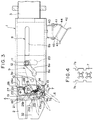
- screw-holding tape two types can be used, one having grooves 7a and 7b opening outwardly along both lateral edges of the tape at a constant pitch, as shown in Fig. 4, and the other having apertures along both lateral edges of the tape at a constant pitch (not shown).
- the mechanism for feeding the screw-holding tape includes a guide slot 8 for a pin described later and provided to pass through one side wall 1a of the casing 1, as shown in Fig. 1.
- the guide slot 8 comprises a rectilinear section 8b extending longitudinally along the casing; an inclined section 8a inclined downwardly and forwardly with respect to the rectlinear section 8b, and a short rectlinear section 8c extending longitudinally along the casing 1 and in front of the inclined section 8a in a continuous manner therewith.
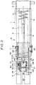
- a two-arm lever 9 is pivotally connected by a pin 10 at one side parallel to the axis B of the driver bit 4 within the slide member 2, as viewed in the sectional plan view of Fig.
- a plate-like pawl member 13 is pivotally connected to the front end of the other arm 9b of the two-arm lever 9 for pivotal motion about a pin 14 and is energized toward the screw-holding tape 7 by a spring 15, which, as apparent from Fig. 1, is hooked at one end to a projection 16 on the side wall of the pawl member 13 and at the other end to a projection 17 provided on the pawl member 13.
- the pawl 13a of the pawl member 13 is normally energized by the spring 15 to thereby be inserted into one of the grooves 7a (Fig. 4) provided at one lateral edge of the screw-holding tape 7 at equal pitches.
- the screw-holding tape 7 is guided through the guide passage, which is defined by a screw-holding tape guiding wall 18 vertically passed through the slide member 2 transversely to the longitudinal direction thereof in Fig. 1 and by a screw-holding tape guiding member 19 of a channel-shaped cross-section (Fig. 2) secured to the slide member 2 opposite the screw-holding tape guide wall 18. Further, the cylinder member 12 at the end of one arm 9a of the two-arm lever 9 is passed through the circular arc-like slot 20 in the side wall of the slide member 2 and extends into the guide slot 8 of the casing 1, as shown in Fig. 2.
- a stopper 30 secured to the front end portion of the casing 1 on the side surface 1b opposite the guide slot 8 so as to extend inwardly of the casing 1 is brought into abutting engagement with the inner end of a slot 31 extending longitudinally of the slide member 2 biased by the spring 5.
- a further T-shaped pawl member 21 (shown by the dotted lines in Figs. 1 and 3) is pivotally connected by a pin 22 at the side opposite the pawl member 13 parallel to the axis B of the driver bit 4, as viewed in the plan sectional view of Fig. 2.
- the pawl member 21 is normally biased toward the screw-holding tape 7 by a torsion spring 24 which engages at one end thereof the inner wall of the slide member 2 and at the other end a projection 23 provided on the lower horizontal portion of the pawl member 21 at the end opposite the pawl 21a (Fig. 3), so that the pawl 21a at the front end of the pawl member 21 is brought into engagement with the groove 7b (Fig. 4) at the other lateral edge of the screw-holding tape 7.
- a torsion spring 24 which engages at one end thereof the inner wall of the slide member 2 and at the other end a projection 23 provided on the lower horizontal portion of the pawl member 21 at the end opposite the pawl 21a (Fig. 3), so that the pawl 21a at the front end of the pawl member 21 is brought into engagement with the groove 7b (Fig. 4) at the other lateral edge of the screw-holding tape 7.
- the pawl member 13 of the other arm 9b of the two-arm lever 9 is forcibly pushed up by the inclined section 8a of the guide slot of the casing 1, and, at that time, the pawl 13a of the pawl member 13 pushes the screw-holding tape 7 up by one-step pitch corresponding to the distance between the adjacent screws on the tape until the tape is restored to the position where indexing of the screw is completed and it is aligned with the axis B of the driver bit 4, as shown in Fig. 1.
- the further pawl member 21 is provided at the side opposite the space from the pawl member 13; however, these pawl members may be provided at the same side if they can be arranged so as not to interfere with each other.
- the grooves or apertures in which the pawls of both pawl members engage must be provided along the same lateral edge of the screw-holding tape 7, with the pitches thereof being offset from each other.
- the slide member 2 is provided with a mechanism for freely pulling back the screw-holding tape 7 in the direction opposite the tape feeding direction A (Figs. 1 and 3).
- the pulling-back mechanism includes a projection 25 (Figs. 2 and 3) provided at the end opposite the pawl 13a of the pawl member 13 and extending inwardly. Particularly referring to Fig.
- a further two-arm lever 26 is pivotally connected at a pin 27 to the interior of the slide member 2, one arm 26a of the other two-arm lever 26 extending into the opening 2a on the upper surface of the slide member 2 and the other arm 26b extending forwardly of the respective projections 25 and 23 of both pawl members 13 and 21 with a slight distance left between it and the pawls.
- the other arm 26b is normally biased to be brought into abutting engagement with the back surface of the tape guide member 19 by a torsion spring 28 wound around the pin 27.
- this pawl pulling-back mechanism when the front end of the one arm 26a of the two-arm lever 26 which exists in the opening 2a is pressed forward, the other arm 26b is pivotally moved backwardly about the pin 27 until it pushes the projections 23 and 25 of both pawl members 13 and 21, so that the pawls 13a and 21a disengage the grooves 7a and 7b at both lateral edges of the screw-holding tape 7, respectively. Accordingly, the screw-holding tape 7 can be freely pulled back. This allows the screws to be replaced by different screws midway during the screw-driving operation, and further allows any screws which have been fed by mistake to be returned to the condition where the screws are to be driven.
- the casing 1 is provided with a tape holding device at the back portion of the side surface corresponding to a tape inserting side.
- the tape-holding device comprises a mount 40 attached to the back portion of the casing 1, and a tape-holding member 42 supported on the mount 40 for pivotal motion about a shaft 41 parallel to-the plane of the casing 1.
- the tape holding member 42 has a guide groove 43 for holding the tape, and the guide groove 43 is supported by the shaft 41 so that it is inclined obliquely and upwardly toward the tape-inserting opening of the slide member 2 at the front of the casing 1, as is apparent from Figs. 1, 3 and 8.
- the tape-holding member 42 is supported at the front end by a short leg 45 and at the back end by a long leg 44, and therefore, has a different radius of pivotal motion at the two ends. Accordingly, during pivotal motion of the tape-holding member 42, the front end of the guide groove 43 describes the path of a small circular arc, and simultaneously, the back end thereof describes the path of a great circular arc, thereby enlarging the range of angle of pivotal motion to guide the tape and smoothly feed the tape.
- an auxially torsion spring 34 is provided around the outer periphery of a cylinder portion 33 enclosing a pin 10 in the center of the pivotal motion of the two-arm lever 9 in the slide member 2.
- One end 34a of the auxially torsion spring 34 is in abutting engagement with a recess of the slide member 2, as shown in Fig. 5, and the other end 34b thereof is in abutting engagement with the stepped portion of the other arm 9b of the two-arm lever 9, as is apparent from Figs. 5 and 6, so that the two-arm lever 9 is normally biased clockwise.
- the two-arm lever 9 begins to be pivotally moved clockwise and the tape 7 is fed by one pitch in the direction A by the pawl 13a of the pawl member 13 of the other arm 9b, which engages the tape 7, and comes to the position shown in Fig. 1.
- the pawl 21a of the further pawl member 21 is pushed out of the groove 7b or aperture against the spring 24 and slides over the tape 7 being fed by one pitch until the pawl 21a fits into the following groove 7b or aperture of the tape again.
- the screw-holding tape-feeding mechanism as set forth in claim 1 is considerably simple in construction and cheap to produce.
- the construction of the tape-pulling back mechanism as set forth in claim 4 enables the tape to be freely pulled back by an operation of a lever, and therefore, the tape can be replaced by a screw-holding tape with a different type of screws during operation as occasion demands.
- the construction of the screw holding mechanism as set forth in claim 5 has a wide range of angles of pivotal motion to guide the tape as compared with that in the prior art, and enables the tape to be smoothly fed.
Landscapes
- Engineering & Computer Science (AREA)
- Mechanical Engineering (AREA)
- Details Of Spanners, Wrenches, And Screw Drivers And Accessories (AREA)
Claims (5)
- Dispositif d'entraînement de vis qui est apte à être accouplé à un tourne-vis et à entraîner en continu, pendant une course de pression, des vis qui sont retenues alignées les unes à la suite des autres dans un ruban (7) de maintien de vis, et qui comprend un boîtier tubulaire (1) accouplé à l'extrémité avant dudit tourne-vis; un élément de coulisseau (2) ajusté à coulissement en vue d'un déplacement en va-et-vient dans le boîtier (1); un ressort de rappel (5) pour rappeler ledit élément de coulisseau (2) vers sa position initiale d'extension pendant une course de rappel; et un mécanisme agencé dans l'élément de coulisseau (2) pour faire avancer pas à pas le ruban (7) de maintien de vis, ledit mécanisme d'avance de ruban incluant une fente de guidage (8) ménagée dans le boîtier (1), un levier (9) à deux bras qui comporte à l'extrémité d'un premier bras (9a) dudit levier (9) à deux bras une broche (11, 12) qui pénètre dans la fente de guidage (8) et est connectée audit élément de coulisseau (2), ledit levier (9) comportant à l'extrémité de son autre bras (9b) un élément (13) à cliquet qui peut venir en prise dans l'une des rainures ou ouvertures ménagées à un bord latéral du ruban (7) de maintien de vis qui est guidé le long d'un passage de guidage (18, 19) transversal à l'élément de coulisseau (2), caractérisé en ce que l'élément (13) à cliquet est connecté à pivotement audit autre bras (9b) et est sollicité au moyen d'un ressort (15) d'une manière telle que le cliquet (13a) prévu sur l'élément (13) à cliquet est sollicité à pivotement vers le ruban (7) de maintien de vis et, simultanément, un autre élément (21) à cliquet comportant un autre cliquet (21a) est connecté à pivotement à l'élément de coulisseau (2) et peut venir en prise sous l'effet d'un autre ressort (24) dans l'une d'autres rainures (7a, 7b), ou ouvertures (7a', 7b') du ruban (7) de maintien de vis, lesdits cliquets (13a, 21a) des éléments (13, 21) à cliquet comportant chacun une première surface orientée dans le sens de l'avance du ruban (7) de maintien de vis et s'étendant d'une façon sensiblement perpendiculaire à la surface du ruban (7) de maintien de vis lorsque les cliquets respectifs (13a, 21a) sont en prise dans l'une des rainures ou ouvertures du ruban (7) de maintien de vis, et une deuxième surface orientée à l'opposé du sens d'avance du ruban de maintien de vis et inclinée de façon à former un angle aigu avec la première surface respective.
- Dispositif d'entraînement de vis selon la revendication 1, dans lequel la fente de guidage (8) inclut en, avant d'un tronçon incliné (8a), un court tronçon rectiligne (8c) qui se raccorde à celui-ci et s'étend dans la direction longitudinale du boîtier (1), grâce à quoi la broche (11, 12) située à l'extrémité du premier bras (9a) dudit levier (9) à deux bras passe dans ce court tronçon linéaire (8c) dans la position d'arrêt du dispositif, position dans laquelle l'élément de coulisseau (2) est dans sa position d'extension maximale hors dudit boîtier (1) sous l'effet du ressort de rappel (5).
- Dispositif d'entraînement de vis selon la revendication 1, qui inclut en outre un organe élastique auxiliaire (31) pour solliciter le levier (9) à deux bras dans le sens opposé au sens dans lequel ledit levier (9) à deux bras est déplacé à pivotement lorsque la broche (11, 12) située à l'extrémité du premier bras (9a) dudit levier (9) à deux bras est déplacée le long d'un tronçon incliné (8a) de la fente de guidage (8) pendant la course de pression.
- Dispositif d'entraînement de vis selon la revendication 1, comprenant en outre un mécanisme (26) agencé dans l'élément de coulisseau (2) pour faire reculer le ruban (7) de maintien de vis dans le sens opposé au sens d'avance du ruban, ledit mécanisme de recul du ruban incluant des saillies (23,25) qui s'étendent l'une vers l'autre et sont agencées, d'une part sur l'élément (13) à cliquet connecté à pivotement au levier (9) à deux bras, et d'autre part sur l'autre élément (21) à cliquet connecté à pivotement audit élément de coulisseau (2), aux extrémités de ces deux éléments (13, 21) à cliquet qui sont éloignées de leur cliquet (13a, 21a), et un levier (26) à deux bras, connecté à pivotement audit élément de coulisseau (2) et apte à venir en prise avec lesdites saillies opposées (23, 25) pour faire reculer les cliquets (13a, 21a) des deux éléments (13, 21) à cliquet dans le sens qui les éloigne de la rainure (7a, 7b) ou de l'ouverture (7a', 7b') du ruban (7) de maintien de vis.
- Dispositif d'entraînement de vis selon la revendication 1, qui comprend en outre un moyen de maintien du ruban agencé sur la partie arrière du côté du boîtier (1), sur le côté de l'élément de coulisseau (2) dans lequel est ménagé un orifice d'insertion du ruban, ledit moyen de maintien du ruban incluant un support fixé à la partie arrière dudit boîtier et un élément de maintien du ruban supporté à pivotement par un arbre formant pivot (41) fixé sur ledit support d'une manière parallèle au plan dudit boîtier (1), l'élément de maintien du ruban étant supporté sur ledit arbre formant pivot (41) d'une manière telle que la rainure de guidage (43) prévue sur ledit élément est inclinée en oblique et vers le haut en direction de l'orifice d'insertion de ruban dudit élément de coulisseau (2).
Applications Claiming Priority (4)
| Application Number | Priority Date | Filing Date | Title |
|---|---|---|---|
| JP281858/92 | 1992-10-20 | ||
| JP4281858A JPH07115306B2 (ja) | 1992-10-20 | 1992-10-20 | ねじ打込装置 |
| JP1671/93 | 1993-01-26 | ||
| JP1993001671U JP2551092Y2 (ja) | 1993-01-26 | 1993-01-26 | ねじ打込装置 |
Publications (2)
| Publication Number | Publication Date |
|---|---|
| EP0593970A1 EP0593970A1 (fr) | 1994-04-27 |
| EP0593970B1 true EP0593970B1 (fr) | 1996-12-27 |
Family
ID=26334943
Family Applications (1)
| Application Number | Title | Priority Date | Filing Date |
|---|---|---|---|
| EP93116032A Expired - Lifetime EP0593970B1 (fr) | 1992-10-20 | 1993-10-05 | Dispositif d'entraînement de vis |
Country Status (3)
| Country | Link |
|---|---|
| US (1) | US5341706A (fr) |
| EP (1) | EP0593970B1 (fr) |
| DE (1) | DE69306906T2 (fr) |
Families Citing this family (45)
| Publication number | Priority date | Publication date | Assignee | Title |
|---|---|---|---|---|
| US5934162A (en) * | 1993-02-17 | 1999-08-10 | Habermehl; G. Lyle | Screwdriver with dual cam slot for collated screws |
| US5839332A (en) * | 1995-04-21 | 1998-11-24 | Max Co., Ltd. | Screw guide in linked-screw tightener |
| US5870933A (en) * | 1995-08-07 | 1999-02-16 | Habermehl; G. Lyle | Advance mechanism for collated screwdriver |
| JPH09285972A (ja) * | 1996-04-18 | 1997-11-04 | Hitachi Koki Co Ltd | ねじ締め工具 |
| DE19628170A1 (de) * | 1996-07-12 | 1998-01-15 | Hilti Ag | Gerät zum Eintreiben von Befestigungselementen in harte Untergründe |
| DE19731948C2 (de) * | 1996-07-26 | 2000-06-21 | Makita Corp | Schraubenförderer in einem kontinuierlich arbeitenden Schraubendrehwerkzeug |
| US5890405A (en) * | 1996-09-11 | 1999-04-06 | Becker; Burkhard | Automated screw driving device |
| US5791207A (en) * | 1997-02-14 | 1998-08-11 | Ahdoot; Ned M. | Fastener feeder |
| WO1999014017A2 (fr) | 1997-09-12 | 1999-03-25 | Jalbert David B | Dispositif tournevis actionne par moteur |
| US6212980B1 (en) | 1999-08-12 | 2001-04-10 | Vermont American Corporation | Screw aligning and guiding device having arrangement which facilitates loading and unloading of screw strip |
| US6164170A (en) * | 1999-12-02 | 2000-12-26 | Habermehl; G. Lyle | Semi-automatic screwdriver for collated screws |
| DE20002058U1 (de) * | 2000-02-04 | 2000-05-04 | AHORN Geräte- und Werkzeuge-Vertiebs GmbH, 35410 Hungen | Magazin mit Magazinband für einen Schrauber |
| CN2497935Y (zh) * | 2001-08-14 | 2002-07-03 | 林昭围 | 螺丝钉带的导引座 |
| US7134367B2 (en) * | 2002-12-09 | 2006-11-14 | Milwaukee Electric Tool Corporation | Fastener feeding system |
| GB2401079B (en) * | 2003-04-30 | 2005-04-27 | Black & Decker Inc | Screw feeder |
| DE102006046707B3 (de) * | 2006-10-02 | 2007-11-29 | Sfs Intec Holding Ag | Einrichtung und System zum automatischen Vorschub von Befestigern und dafür geeigneter Magazinierstreifen |
| DE102007026552B4 (de) * | 2007-06-08 | 2010-04-01 | Helfast Gmbh & Co. Kg I.G. | Vorschubeinrichtung für ein Eintreibwerkzeug zum Zuführen von Befestigungsmitteln, insbesondere Schrauben |
| KR101792291B1 (ko) | 2009-11-11 | 2017-10-31 | 헨롭 리미티드 | 패스너 공급 장치 |
| US8382414B2 (en) * | 2010-01-11 | 2013-02-26 | National Nail Corp. | Threaded fastener and related method of installation |
| US8672204B2 (en) | 2010-01-13 | 2014-03-18 | National Nail Corp. | Fastener, installation tool and related method of use |
| US8955210B2 (en) | 2010-01-13 | 2015-02-17 | National Nail Corp. | Fastener, installation tool and related method of use |
| US9144896B2 (en) | 2010-01-13 | 2015-09-29 | National Nail Corp. | Fastener, installation tool and related method of use |
| US9120214B2 (en) | 2010-01-13 | 2015-09-01 | National Nail Corp. | Fastener, installation tool and related method of use |
| US9802300B2 (en) | 2010-01-13 | 2017-10-31 | National Nail Corp. | Fastener, installation tool and related method of use |
| USD704018S1 (en) | 2012-01-04 | 2014-05-06 | National Nail Corp. | Fastener installation tool |
| US11149445B2 (en) | 2017-08-15 | 2021-10-19 | National Nail Corp. | Hidden fastener unit and related method of use |
| US11261893B2 (en) | 2017-08-15 | 2022-03-01 | National Nail Corp. | Hidden fastener unit and related method of use |
| USD1019365S1 (en) | 2023-05-31 | 2024-03-26 | National Nail Corp. | Fastener positioning device |
| USD945870S1 (en) | 2020-11-17 | 2022-03-15 | National Nail Corp. | Fastener positioning device |
| US11898357B2 (en) | 2017-08-15 | 2024-02-13 | National Nail Corp. | Hidden fastener unit and related method of use |
| US11111679B2 (en) | 2017-08-15 | 2021-09-07 | National Nail Corp. | Hidden fastener unit and related method of use |
| US12234654B2 (en) | 2017-08-15 | 2025-02-25 | National Nail Corp. | Hidden fastener unit and related method of use |
| USD924044S1 (en) | 2019-11-20 | 2021-07-06 | National Nail Corp. | Fastener positioning device |
| US10780489B2 (en) | 2018-02-21 | 2020-09-22 | Newfrey Llc | Tool-free opening tape feed receiver for a self-piercing rivet machine |
| US10456826B2 (en) | 2018-02-21 | 2019-10-29 | Newfrey Llc | Tape feed apparatus and method for a self-piercing rivet machine |
| US10758966B2 (en) | 2018-02-21 | 2020-09-01 | Newfrey Llc | Processor-controlled tape feed apparatus and method for a self-piercing rivet machine |
| USD842086S1 (en) | 2018-02-26 | 2019-03-05 | National Nail Corp. | Screw |
| USD1138705S1 (en) | 2018-05-18 | 2026-08-04 | National Nail Corp. | Fastener positioning device |
| CN108730707B (zh) * | 2018-08-21 | 2024-01-09 | 桂林智神信息技术股份有限公司 | 一种相机快装快拆板的止动结构 |
| EP3666468A1 (fr) * | 2018-12-10 | 2020-06-17 | Hilti Aktiengesellschaft | Dispositif de séparation, chargeur et système de fixation |
| US12365066B2 (en) | 2020-10-14 | 2025-07-22 | Simpson Strong-Tie Company Inc. | Fastener installation systems and adapters |
| US11731252B2 (en) | 2021-01-29 | 2023-08-22 | National Nail Corp. | Screw guide and related method of use |
| US12297649B2 (en) | 2022-10-27 | 2025-05-13 | Primesource Building Products, Inc. | Deck clip |
| US11938596B1 (en) | 2023-01-26 | 2024-03-26 | National Nail Corp. | Fastener installation tool and related method of use |
| USD1022684S1 (en) | 2023-02-23 | 2024-04-16 | National Nail Corp. | Fastener positioning device |
Family Cites Families (7)
| Publication number | Priority date | Publication date | Assignee | Title |
|---|---|---|---|---|
| US4014225A (en) * | 1973-02-02 | 1977-03-29 | Bulten-Kanthal Aktiebolag | Power-driven screwdriver |
| US3910324A (en) * | 1974-04-29 | 1975-10-07 | Duo Fast Corp | Rotary entry fastener driving tool |
| DE2541046C2 (de) * | 1975-09-15 | 1982-10-14 | Feinwerkbau Helfer & Co KG, 3261 Möllenbeck | Vorschubeinrichtung an einem Eintreibwerkzeug zum Zuführen von Befestigungsmitteln, insbesondere Schrauben |
| US4404877A (en) * | 1981-10-09 | 1983-09-20 | Sanyo Industries, Ltd. | Power-driven screwdriver |
| CA2044088A1 (fr) * | 1990-06-18 | 1991-12-19 | Takeo Fujiyama | Visseuse a mecanisme de support et de guidage de courroie |
| US5083483A (en) * | 1991-01-02 | 1992-01-28 | Santomi Shoji Co., Ltd. | Screw positioning device |
| DE9207847U1 (de) * | 1992-06-11 | 1992-09-17 | Helfer & Co KG, 3260 Rinteln | Vorschubeinrichtung an einem Eintreibwerkzeug zum Zuführen von Befestigungsmitteln, insbesondere Schrauben |
-
1993
- 1993-09-29 US US08/128,802 patent/US5341706A/en not_active Expired - Lifetime
- 1993-10-05 EP EP93116032A patent/EP0593970B1/fr not_active Expired - Lifetime
- 1993-10-05 DE DE69306906T patent/DE69306906T2/de not_active Expired - Fee Related
Also Published As
| Publication number | Publication date |
|---|---|
| EP0593970A1 (fr) | 1994-04-27 |
| DE69306906D1 (de) | 1997-02-06 |
| US5341706A (en) | 1994-08-30 |
| HK1006551A1 (en) | 1999-03-05 |
| DE69306906T2 (de) | 1997-07-24 |
Similar Documents
| Publication | Publication Date | Title |
|---|---|---|
| US5341706A (en) | Screw-driving device | |
| EP0064364B1 (fr) | Outil pour la mise en place de moyens de fixation | |
| US4553302A (en) | Installation tool, tangless helically coiled insert | |
| US5322189A (en) | Fastener feeding mechanism in fastener driving device | |
| US5402695A (en) | Feeding device for an inserting tool for supplying fasteners, particularly screws | |
| US4014488A (en) | Fastener feed apparatus and method | |
| US7231854B2 (en) | Connected-screw driver | |
| US5350103A (en) | Easy fastener jam removal tool | |
| US6296166B1 (en) | Belt feeding device for stapler | |
| US5671645A (en) | Screw supply device for coupled screw tightening machine | |
| EP1197301B1 (fr) | Outil de scellement actionné par poudre et déclenché par compression | |
| HK1006551B (en) | Screw-driving device | |
| EP0191183B1 (fr) | Machine de banderolage | |
| US7455205B2 (en) | Magazining device for a drive-in power tool | |
| AU2016362825B2 (en) | Fastener driving system | |
| EP0075664A2 (fr) | Cartouche pour ruban encreur avec dispositif anti-retour pour la bobine réceptrice | |
| WO2023225493A1 (fr) | Dispositif de positionnement d'une série d'éléments de fixation devant un dispositif d'entraînement, et procédés et éléments associés | |
| JPH08139492A (ja) | 電子部品挿入機における電子部品供給装置 | |
| JP2998882B2 (ja) | 連結ネジ用ネジ締め機におけるネジ送り機構 | |
| JPH0657563U (ja) | ねじ打込装置 | |
| JP2622241B2 (ja) | ねじ打込装置 | |
| JP2998886B2 (ja) | 連結ネジ用ネジ締め機における連結ネジの逆抜き機構 | |
| JP2900982B2 (ja) | 連結ネジ用ネジ締め機における連結ネジの逆抜き機構 | |
| JPH07266250A (ja) | ネジ締め機における連結ネジの送りミス防止装置 | |
| US5056943A (en) | Line-spacing device for a typewriter or the like |
Legal Events
| Date | Code | Title | Description |
|---|---|---|---|
| PUAI | Public reference made under article 153(3) epc to a published international application that has entered the european phase |
Free format text: ORIGINAL CODE: 0009012 |
|
| AK | Designated contracting states |
Kind code of ref document: A1 Designated state(s): DE FR GB IT SE |
|
| 17P | Request for examination filed |
Effective date: 19940422 |
|
| 17Q | First examination report despatched |
Effective date: 19941209 |
|
| GRAG | Despatch of communication of intention to grant |
Free format text: ORIGINAL CODE: EPIDOS AGRA |
|
| GRAH | Despatch of communication of intention to grant a patent |
Free format text: ORIGINAL CODE: EPIDOS IGRA |
|
| GRAH | Despatch of communication of intention to grant a patent |
Free format text: ORIGINAL CODE: EPIDOS IGRA |
|
| GRAA | (expected) grant |
Free format text: ORIGINAL CODE: 0009210 |
|
| AK | Designated contracting states |
Kind code of ref document: B1 Designated state(s): DE FR GB IT SE |
|
| REF | Corresponds to: |
Ref document number: 69306906 Country of ref document: DE Date of ref document: 19970206 |
|
| ITF | It: translation for a ep patent filed | ||
| ET | Fr: translation filed | ||
| PLBE | No opposition filed within time limit |
Free format text: ORIGINAL CODE: 0009261 |
|
| STAA | Information on the status of an ep patent application or granted ep patent |
Free format text: STATUS: NO OPPOSITION FILED WITHIN TIME LIMIT |
|
| 26N | No opposition filed | ||
| REG | Reference to a national code |
Ref country code: GB Ref legal event code: IF02 |
|
| PGFP | Annual fee paid to national office [announced via postgrant information from national office to epo] |
Ref country code: GB Payment date: 20031001 Year of fee payment: 11 |
|
| PGFP | Annual fee paid to national office [announced via postgrant information from national office to epo] |
Ref country code: FR Payment date: 20031016 Year of fee payment: 11 |
|
| PGFP | Annual fee paid to national office [announced via postgrant information from national office to epo] |
Ref country code: SE Payment date: 20031020 Year of fee payment: 11 |
|
| PGFP | Annual fee paid to national office [announced via postgrant information from national office to epo] |
Ref country code: DE Payment date: 20031029 Year of fee payment: 11 |
|
| PG25 | Lapsed in a contracting state [announced via postgrant information from national office to epo] |
Ref country code: GB Free format text: LAPSE BECAUSE OF NON-PAYMENT OF DUE FEES Effective date: 20041005 |
|
| PG25 | Lapsed in a contracting state [announced via postgrant information from national office to epo] |
Ref country code: SE Free format text: LAPSE BECAUSE OF NON-PAYMENT OF DUE FEES Effective date: 20041006 |
|
| PG25 | Lapsed in a contracting state [announced via postgrant information from national office to epo] |
Ref country code: DE Free format text: LAPSE BECAUSE OF NON-PAYMENT OF DUE FEES Effective date: 20050503 |
|
| GBPC | Gb: european patent ceased through non-payment of renewal fee |
Effective date: 20041005 |
|
| EUG | Se: european patent has lapsed | ||
| PG25 | Lapsed in a contracting state [announced via postgrant information from national office to epo] |
Ref country code: FR Free format text: LAPSE BECAUSE OF NON-PAYMENT OF DUE FEES Effective date: 20050630 |
|
| REG | Reference to a national code |
Ref country code: FR Ref legal event code: ST |
|
| PG25 | Lapsed in a contracting state [announced via postgrant information from national office to epo] |
Ref country code: IT Free format text: LAPSE BECAUSE OF NON-PAYMENT OF DUE FEES;WARNING: LAPSES OF ITALIAN PATENTS WITH EFFECTIVE DATE BEFORE 2007 MAY HAVE OCCURRED AT ANY TIME BEFORE 2007. THE CORRECT EFFECTIVE DATE MAY BE DIFFERENT FROM THE ONE RECORDED. Effective date: 20051005 |