EP0594040A1 - Méthode pour changer l'écartement d'un véhicule ferroviaire, véhicule ferroviare avec écartement variable et installation à terre correspondante - Google Patents
Méthode pour changer l'écartement d'un véhicule ferroviaire, véhicule ferroviare avec écartement variable et installation à terre correspondante Download PDFInfo
- Publication number
- EP0594040A1 EP0594040A1 EP93116504A EP93116504A EP0594040A1 EP 0594040 A1 EP0594040 A1 EP 0594040A1 EP 93116504 A EP93116504 A EP 93116504A EP 93116504 A EP93116504 A EP 93116504A EP 0594040 A1 EP0594040 A1 EP 0594040A1
- Authority
- EP
- European Patent Office
- Prior art keywords
- wheel
- truck
- wheels
- spacing
- rails
- Prior art date
- Legal status (The legal status is an assumption and is not a legal conclusion. Google has not performed a legal analysis and makes no representation as to the accuracy of the status listed.)
- Granted
Links
Images


Classifications
-
- B—PERFORMING OPERATIONS; TRANSPORTING
- B61—RAILWAYS
- B61H—BRAKES OR OTHER RETARDING DEVICES SPECIALLY ADAPTED FOR RAIL VEHICLES; ARRANGEMENT OR DISPOSITION THEREOF IN RAIL VEHICLES
- B61H9/00—Brakes characterised by, or modified for, their application to special railway systems or purposes
-
- B—PERFORMING OPERATIONS; TRANSPORTING
- B61—RAILWAYS
- B61F—RAIL VEHICLE SUSPENSIONS, e.g. UNDERFRAMES, BOGIES OR ARRANGEMENTS OF WHEEL AXLES; RAIL VEHICLES FOR USE ON TRACKS OF DIFFERENT WIDTH; PREVENTING DERAILING OF RAIL VEHICLES; WHEEL GUARDS, OBSTRUCTION REMOVERS OR THE LIKE FOR RAIL VEHICLES
- B61F7/00—Rail vehicles equipped for use on tracks of different width
Definitions
- the present invention relates to a method for changing, in accordance with a change of a track gauge, i.e. a spacing between a pair of rails of a railway or track, a wheel-spacing (referred to hereafter also as “wheel gauge”), i.e. a spacing between left and right wheels of a truck supporting a vehicle body thereon so that the vehicle constituted by the vehicle body and the changeable or variable wheel-spacing truck can run on rails of different track gauges.
- a variable wheel-spacing truck namely, a truck having wheels of variable wheel-spacing, and to a ground facility therefor.
- the wheel-spacing or gauge of the truck supporting the vehicle body is always maintaind constant according to the constant track gauge, and it is impossible for a vehicle to run from a railway of one track gauge onto another railway of a different track gauge.
- a vehicle runs on a railway having a wider or standard track gauge
- a vehicle runs only on a railway having a narrower track gauge.
- the object of the present invention is to provide a tuck wheel-spacing changing method, a variable wheel-spacing truck and a ground facility therefor, in which the truck may be a self-propelled truck or not, i.e. a tracted truck; running stability of the vehicle is not inferior to a conventional truck of the fixed wheel-spacing; the ground facility includes no moving part; and the wheel-spacing changing mechanism has easy maintenanability.
- a transverse beam, of each track frame constituted by the transom and a side beam, extending perpendicularly to a side beam and supporting a part of the vehicle weight is upwardly pushed by the associated auxiliary wheel just before the truck advances into the intermediate railway, whereby the locking means restricting the positional relation between a tip portion of the transom of one bogie frame and the side beam of the other bogie frame is released and maintained at a released condition. This condition is continued until the truck advances completely onto the wider track gauge railway after passing through the junction railway.
- the truck wheel-spacing is widened until the wheel-spacing coincides with the wider track gauge, and the spacing between the pair of side beams each constituting a part of the bogie frame is also widened in accordance with the widening of the truck wheel-spacing.
- the vehicle weight raised upwardly by the auxiliary wheel is loaded again on the tip portions of the transverse beams, and the transverse positional relation between the side beams and the transverse beams is again fixed and maintained at a fixed condition by means of the locking means.
- the spacing between the bogie frames and the truck wheel-spacing can be maintained at a constant value, and the truck is assured to run on a new wider track gauge railway with sufficient stability.
- the wheel-spacing can be suitably changed according to a method similar to the above-mentioned one.
- the locking means for fixing the truck wheel-spacing can be released by pushing upwards the auxiliary wheels mounted on the bogie frames by utilizing a part of the driving or advancing force of the truck, without any external power for the unlocking.
- the sliding of the wheel(s) to a new position is carried out also by utilizing a part of the driving (advancing) force of the truck, wherein the track rails and the guide rails cooperate to push the wheel(s), and the wheel-spacing is changed also without any special power.
- the locking force for fixing the wheel-spacing is produced when the auxiliary wheels mounted on the truck is separated from the running path means and the vehicle weight is again loaded on the transverse beams of the truck.
- one of the wheels may be prevented from moving relative to the wheel shaft in the axial direction of the shaft while permitting the other wheel to slide relative to the wheel shaft in the axial direction; or both of the wheels may freely slide relative to the wheel shaft in the axial direction.
- a ground facility comprises a) a railway having a narrower track gauge, a railway having a wider track gauge and a junction railway including a middle portion where the track gauge gradually changes and end portions where the track gauge is constant, and b) running path means for the auxiliary wheels extending within the intermediate railway, the running path means being arranged, in plan view, so that a predetermined positional relation to the railway rales of the changing track gauge is maintained, and being shaped, in elevational view, so that a top surface of the path means is higher than the top surfaces of the rails of the junction railway at a region beyond the whole length of the middle portion, while both end portions thereof are continuously inclined downwards to respective ends.
- variable wheel-spacing truck having the above-mentioned arrangement according to the present invention
- one and another transverse beams of one and another "T"-shaped bogie frames are respectively moved relative to the opposite side beams of the opposite bogie frames while maintaining a parallel relation therebetween at a certain spacing therebetween in the vehicle proceeding direction by the help of respective link members.
- the two transversel beams are moved closer to or apart from each other while maintaing their parallel relationship.
- one of the left and right wheels may be fixed to the wheel shaft so as to prevent the wheel from moving relative to the wheel shaft in the axial direction of the shaft, whereby the wheel shaft portion on the fixed wheel side is engaged with and supported by the bogie frame through the axle box and the supporting means therefor, or both of the left and right wheels may be allowed to slide relative to the wheel shaft in the axial direction of the shaft.
- the above-mentioned locking means may include the auxiliary wheels between the left and right wheels to serve as a force-acting point upon separating the bogie frames from each other in a vertical direction for releasing the locking condition, or upon engaging for locking.
- the above-mentioned locking means may be so constructed that one bogie frame on one side of the vehicle is raised or lowered relative to the other bogie frame by use of the auxiliary wheels serving as the force-acting point, which are disposed transversely outside of the running wheel, thereby effecting unlocking or locking by the locking means.
- the above-mentioned locking means may include a locking pin which releases the two bogie frames from each other or engages the two bogie frames pivotally with each other by raising or lowering the auxiliary wheel, respectively.
- a lever member is inclined around a pivot point by the auxiliary wheel, thereby raising an end portion of the link member together with the locking pin as releasing the connection between the transversal beam of one bogie frame and the side beam of another bogie frame.
- the transversely slidable wheel may be adapted to rotate around the wheel shaft.
- the left and right wheels can rotate independently relative to each other, the running stability along a straight railway is excellent.
- the slidable wheel may be adapted to be prevented from rotating relative to the wheel shaft.
- the behavior of these wheels is the same as conventional wheels as far as the rotating feature is concerned.
- a ground facility according to the present invention having the above-mentioned arrangement comprises rails and running path means, but no moving part.
- the rails serve to press the wheels when a vehicle moves from a wider track gauge railway onto a narrower track gauge railway.
- the above-mentioned ground facility may comprise c) a pair of inside guide rails which are arranged to extend beyond the whole length of the running path means and within the above-mentioned junction railway at inside of the pair of rails in plan view, while maintaining a predetermined dimensional relation relative to the railway tracks (rails) with their heights maintained higher than the top surface of the rails.
- the ground facility is composed of rails, running path means and inside guide rails, but includes no moving part.
- the inside guide rails serve to press the wheels when a vehicle moves from a wider track gauge railway into a narrower track gauge railway.
- the above-mentioned ground facility may comprise a pair of outside guide rails which are arranged to extend beyond the whole length of the running path means and within the above-mentioned junction railway section at outside of the pair of rails in plan view, while maintaining a predetermined dimensional relation relative to the rails or tracks, with their heights maintained higher than the top surface of the rails.
- the ground facility is composed of rails, running path means and outside guide rails, but includes no moving part.
- the outside guide rails serve to press the wheels when a vehicle moves from a wider track gauge railway onto a narrower track gauge railway. Since the wheel pressing force is relatively greater in this ground facility in comparison with in that not having the arrangement d), the length of the junction railway section of this ground facility can be shortened in comparison with the ground facility not having arrangement d).
- the above-mentioned ground facility may comprise a pair of inside guide rails which are arranged to extend beyond the whole length of the running path means and within the above-mentioned junction railway section at positions inside of the pair of rails in plan view, while maintaining a predetermined dimensional relation relative to the tracks or rails, with their heights maintained higher than the top surface of the rails, and a pair of outside guide rails which are arranged to extend beyond the whole length of the running path means and within the above-mentioned junction railway section at outside of the pair of rails in plan view, while maintaining a predetermined dimensional relation relative to the tracks or rails, with their heights made higher than the top surface of the rails.
- the ground facility is composed of railway rails, running path means, inside guide rails and outside guide rails, but includes no moving part. It is possible for a vehicle to move from a railway having a narrower track gauge into a railway having a wider track gauge and also to move from a railway having a wider truck gauge into a railway having a narrower truck gauge.
- the inside guide rails serve to press the wheels
- the outside guide rails serve to press the wheels.
- the running path means may be located g) inside of the pair of rails or h) outside of the same, the former arrangement corresponding to a truck having a structural feature F or H where the auxiliary wheel is disposed inside of the rail, while the latter arrangement to a truck having a structural feature G where the auxiliary wheel is disposed outside of the rail.
- Figs. 1A to 1C show a sequence of changing a wheel-spacing or track gauge, wherein Fig. 1A is a side view of a self-propelled truck according to a first embodiment of a variable wheel-spacing truck of a first type of the present invention and a ground facility with running paths disposed outside of rails; Fig. 1B is a plan view of the ground facility shown in Fig. 1A; and Fig. 1C is elevational views of the truck shown in Fig. 1A when standing at locations A to G upon a truck wheel-spacing changing operation.
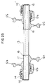
- Figs. 2A and 2B show an embodiment of a ground facility according to the present invention, wherein Fig. 2A is a side view showing running paths arranged outside of both rails, while the facility having inside guide rails and outside guide rails; and Fig. 2B is a plan view of the ground facility shown in Fig. 2A.
- Figs. 3A and 3B show another embodiment of the ground facility, wherein Fig. 3A is a side view showing running paths arranged outside of both rails, and inside guide rails; and Fig. 3B is a plan view of the ground facility shown in Fig. 3A.
- Figs. 4A to 4C show a variable wheel-spacing truck according to the first embodiment, wherein Fig. 4A is a plan view in case of on a narrower track gauge railway and Fig. 4B is a plan view in case of on a wider track gauge railway; and Fig. 4C is an enlarged view of a part H of the truck of Fig. 4A.
- Figs. 5A and 5B are elevational views of the truck shown in Figs. 4 in case of the narrower track gauge railway and in case of on the wider track gauge railway, respectively.
- Fig. 6 is a side view of a truck shown in Figs. 4A and 4B in case auxiliary wheel is not acting.
- Fig. 7A, 7B and 7C are elevational views of side beams, an auxiliary wheel, a transom and a wheel shaft of a truck shown in Fig. 1B at positions A and B, at positions C and D, and at positions F and G, respectively.
- Figs. 8A to 8C show a variable wheel-spacing truck according to the first embodiment as applied to a tracted truck, wherein Figs,. 8A and 8B are plan views in case of on a narrower track gauge railway and in case of on a wider track gauge railway, respectively; and Fig. 8C is an enlarged view of a part H of the truck of Fig. 8A.
- Fig. 9 is an enlarged sectional view of a wheel shaft of a self-propelled truck according to an embodiment of the first type of the present invention, wherein the upper potion of the figure shows the shaft in case of a wider track gauge or wheel-spacing, while the lower portion of the same shows that in case of a narrower track gauge or wheel-spacing.
- Fig. 10 is an enlarged sectional view of a wheel shaft of a tracted truck according to an embodiment of the first type of the present invention, wherein the upper potion of the figure shows the shaft in case of a wider wheel-spacing or track gauge, while the lower portion of the same shows that in case of a narrower wheel-spacing or track gauge.
- Figs. 11A to 11C show a sequence of changing truck wheel-spacing or track gauge, wherein Fig. 11A is a side view of a self-propelled truck according to a second embodiment of a variable wheel-spacing truck of the present invention and a ground facility with running paths disposed inside of rails; Fig. 11B is a plan view of the ground facility shown in Fig. 11A; and Fig. 11C is elevational views of the truck shown in Fig. 11A when standing at locations A to G upon a truck wheel-spacing changing operation.
- Figs. 12A and 12B show an embodiment of a ground facility, wherein Fig. 12A is a side view showing running paths arranged inside of both rails, inside guide rails and outside guide rails; and Fig. 12B is a plan view of the ground facility shown in Fig. 12A.
- Figs. 13A and 13B show another embodiment of the ground facility, wherein Fig. 13A is a side view showing running paths arranged inside of both rails, and inside guide rails, but no outside guide rail; and Fig. 13B is a plan view of the ground facility shown in Fig. 13A.
- Figs. 14A to 14C show a variable wheel-spacing truck according to the second embodiment, wherein Fig. 14A is a plan view in case of a narrower track gauge and Fig. 14B is a plan view in case of a wider track gauge; and Fig. 14C is an enlarged view of a part H of the truck shown in Fig. 14A.
- Figs. 15A and 15B are elevational views of the variable wheel-spacing truck shown in Figs. 14A to 14C in case of a narrower track gauge and in case of a wider track gauge, respectively.
- Fig. 16 is a side view of the truck shown in Figs. 14A and 14B in case auxiliary wheel is not acting.
- Figs. 17A to 17C show a variable wheel-spacing truck according to the second embodiment as applied to a tracted truck, wherein Figs. 17A and 17B are plan views in case of a narrower track gauge and in case of a wider track gauge, respectively; and Fig. 17C is an enlarged view of a part H of the truck shown in Fig. 17A.
- Figs. 18A to 18C show a sequence of changing truck wheel-spacing or track gauge, wherein Fig. 18A is a side view of a self-propelled truck according to the third embodiment of a variable wheel-spacing truck of the present invention and a ground facility including running paths disposed inside of both rails; Fig. 18B is a plan view of the ground facility shown in Fig. 18A; and Fig. 18C is elevational views of the truck shown in Fig. 18A when standing at locations A to G upon a truck wheel-spacing changing operation.
- Figs. 19A to 19C show a variable wheel-spacing truck according to the third embodiment, wherein Fig. 19A is a plan view in case of a narrower track gauge and Fig. 19B is a plan view in case of a wider track gauge; and Fig. 19C is an enlarged view of a part H of the truck shown in Fig. 19A.
- Figs. 20A and 20B are elevational views of the variable wheel-spacing truck shown in Figs. 19A to 19C in case of a narrower track gauge and in case of a wider track gauge, respectively.
- Fig. 21 is a side view of the variable wheel-spacing truck shown in Figs. 19A to 19C in case auxiliary wheel is not acting.
- Fig. 22 is an enlarged perspective view showing a main part of a locking and unlocking means of a lever type in the variable wheel-spacing truck shown in Figs. 19A to 19C.
- Figs. 23A to 23C show a variable wheel-spacing truck according to the third embodiment as applied to a tracted truck, wherein Figs. 23A and 23B are plan views in case of a narrower track gauge and in case of a wider track gauge, respectively; and Fig. 23C is an enlarged view of a part H of the truck shown in Fig. 23A.
- Fig. 24 is an enlarged sectional view of a wheel shaft of a self-propelled truck according to an embodiment of the second type of the present invention, wherein the upper potion of the figure shows the shaft in case of a wider wheel-spacing or track gauge, while the lower portion of the same shows that in case of a narrower wheel-spacing or track gauge.
- Fig. 25 is an enlarged sectional view of a wheel shaft of a variable wheel-spacing truck of a tracted type according to an embodiment of the second type of the present invention, wherein the upper potion of the figure shows the shaft in case of a wider wheel-spacing or track gauge and the lower half portion of the figure shows the shaft in case of a narrower wheel-spacing or track gauge.
- Figs. 26A to 26C show a sequence of changing truck wheel-spacing or track gauge similarly to Figs. 1A to 1C, wherein Fig. 26A is a side view of a self-propelled truck of the second type according to a fourth embodiment of a variable wheel-spacing truck of the present invention and a ground facility including running paths disposed outside of both rails; Fig. 26B is a plan view of the ground facility shown in Fig. 26A; and Fig. 26C is elevational views of the truck shown in Fig. 26A when standing at locations A to G during a truck wheel gauge changing operation.
- Figs. 27A to 27C show a variable wheel-spacing truck according to the fourth embodiment similar to Figs. 4A to 4C, wherein Fig. 27A is a plan view in case of a narrower track gauge and Fig. 27B is a plan view in case of a wider track gauge; and Fig. 27C is an enlarged view of a part H of the truck shown in Fig. 27A.
- Figs. 28A and 28B similar to Figs. 5A and 5B, are elevational views of the truck shown in Figs. 27A to 27C in case of a narrower track gauge and in case of a wider track gauge, respectively.
- Fig. 29 is a side view, similar to Fig. 6, of a variable wheel-spacing truck shown in Figs. 27A to 27C in case auxiliary wheel is not acting.
- Fig. 30A, 30B and 30C are elevational views of side beams, an auxiliary wheel, a transom and a wheel of a truck shown in Figs. 27A to 27B, at positions A and B, at positions C and D, and at positions F and G, similarly to Figs. 7A, 7B and 7C, respectively.
- Figs. 31A to 31C similar to Figs. 8A to 8C, show a variable wheel-spacing truck according to the fourth embodiment as applied to a tracted truck, wherein Figs. 31A and 31B are plan views in case of a narrower track gauge and in case of a wider truck gauge, respectively; and Fig. 31C is an enlarged view of a part H of the truck of Fig. 31A.
- Figs. 32A to 32C show a sequence of changing truck wheel-spacing or track gauge similarly to Figs. 11A to 11C, wherein Fig. 32A is a side view of a self-propelled truck according to a second embodiment of a variable gauge truck of the second type, namely a fifth embodiment of the present invention, and a ground facility including running paths disposed inside of both rails; Fig. 32B is a plan view of the ground facility shown in Fig. 32A; and Fig. 32C is elevational views of the truck shown in Fig. 32A when standing at locations A to G upon a truck wheel-spacing changing operation.
- Figs. 33A to 33C show a variable wheel-spacing truck according to the fifth embodiment similarly to Figs. 14A to 14C, wherein Fig. 33A is a plan view in case of a narrower track gauge and Fig. 33B is a plan view in case of a wider track gauge; and Fig. 33C is an enlarged view of a part H of the truck shown in Fig. 33A.
- Figs. 34A and 34B similar to Figs. 15A and 15B, are elevational views of the truck shown in Figs. 33A to 33C in case of a narrower track gauge and in case of a wider track gauge, respectively.
- Fig. 35 similar to Fig. 16, is a side view of a truck shown in Figs. 33A to 33C in case auxiliary wheel is not acting.
- Figs. 36A to 36C similar to Figs. 17A to 17C, show a variable wheel-spacing truck according to the fifth embodiment as applied to a tracted truck, wherein Figs. 36A and 36B are plan views in case of a narrower track gauge and in case of a wider track gauge, respectively; and Fig. 36C is an enlarged view of a part H of the truck shown in Fig. 36A.
- Figs. 37A to 37C similar to Figs. 18A to 18B, show a sequence of changing truck wheel-spacing or track gauge
- Fig. 37A is a side view of a self-propelled truck according to a third embodiment of a variable gauge truck of the second type, namely a sixth embodiment of the present invention and a ground facility including running paths disposed inside of both rails
- Fig. 37B is a plan view of the ground facility shown in Fig. 37A
- Fig. 37C is elevational views of the truck shown in Fig. 37A when standing at locations A to G upon a truck wheel-spacing changing operation.
- Figs. 38A to 38C similar to Figs. 19A to 19B, show a variable wheel-spacing truck according to the sixth embodiment, wherein Fig. 38A is a plan view in case of a narrower track gauge and Fig. 38B is a plan view in case of a wider track gauge; and Fig. 38C is an enlarged view of a part H of the truck shown in Fig. 38A.
- Figs. 39A and 39B are elevational views of the truck shown in Figs. 38A to 38C in case of a narrower track gauge and in case of a winder track gauge, respectively, similarly to Figs. 20A and 20B.
- Fig. 40 similar to Fig. 21, is a side view of a variable wheel-spacing truck shown in Figs. 38A to 38C in case auxiliary wheel is not acting.
- Figs. 41A to 41C similar to Figs. 23A to 23C, show a variable wheel-spacing truck according to the sixth embodiment as applied to a tracted truck, wherein Figs. 41A and 41B are plan views in case of a narrower track gauge and in case of a wider track gauge, respectively; and Fig. 41C is an enlarged view of a part of the truck shown in Fig. 41A.
- variable wheel-spacing truck and a ground facility therefor as well as a truck wheel-spacing changing method according to preferred embodiments of the present invention will be described below.
- a variable wheel-spacing truck of a first type in which one of a pair of wheels is slidable relative to the wheel shaft in the axial direction of the shaft and the other wheel is prevented from moving axially relative to the wheel shaft.
- Figs. 1A to 8C show arrangements for a wheel-spacing changing method to be used for the variable wheel-spacing truck according to a first embodiment, in which running paths for auxiliary wheels are arranged outside of a railway track, and locking means for prohibiting change of the wheel-spacing is released by the help of a force acted on from an auxiliary wheel.
- 11A to 17C show arrangements for a wheel-spacing changing method to be used for a variable wheel-spacing truck according to a second embodiment, in which running paths for auxiliary wheels are arranged inside of a railway track, and locking means for prohibiting the change of the wheel-spacing is released by the help of a force acted on from an auxiliary wheel.
- FIG. 18A to 23C show arrangements for a wheel-spacing changing method to be used for a variable wheel-spacing truck according to a third embodiment, in which running paths for auxiliary wheels are arranged inside of a railway track, and a lock pin constituting a part of locking means for prohibiting the change of the wheel-spacing is effected or released by the help of a force acted on from an auxiliary wheel and a lock pin included in the locking means.
- Fig. 9 and 10 are common to the trucks according to the above embodiments.
- Figs. 1A is a side view of a ground facility for changing a truck wheel-spacing and a variable wheel-spacing truck, according to the first embodiment, standing typically at a location A and at a location D;
- Fig. 1B is a plan view of the track gauge-change ground facility;
- Fig. 1C is elevational views of the ground facility and the variable wheel-spacing truck according to the first embodiment when standing at locations A to G.
- FIGs. 1A to 1C we now explain a sequence of changing the wheel-spacing from a magnitude for a narrower track gauge to a magnitude for a wider track gauge (in the following description, details of structure of truck 1 are shown in Figs. 4A to 10).
- variable wheel-spacing truck 1 runs on rails 31, 31 of a narrower track gauge railway.
- each of a pair of wheels 12, 12' have intruded into between inside guide rails 34 and an outside guide rails 35.
- auxiliary wheels 21 run on running paths 36, the auxiliary wheels 21 are raised upwards, whereby tip portions of transverse beams 4 of bogie frames 2 are also raised and projections 8 formed on lower surfaces of the transverse beams 4 are drawn out of positioning holes 7 located on outer portions of side beams 3, thereby allowing the pair of wheels 12, 12' and the bogie frames 2, 2 to move relative to each other in an entending direction of the rail load tie, i.e. axial or longitudinal direction of a shaft 13.
- the wheels 12, 12' move from rails 31, 31 of the narrower track gauge railway to rails 32, 32 of a junction railway section, whereby the back-gauge-side surfaces of the wheels 12, 12' are pressed outwards by the inside guide rails 34, 34 and the spacing between two wheels 12, 12' is gradually increased or widened as the truck moves along the rails 32, 32 of the junction railway section. According to the widening of the spacing between the wheels 12, 12', the spacing between the bogie frames 2, 2 supporting these wheels is also widened. Since the fixed wheel 12' is fixed to the wheel shaft 13, the slidable wheel 12 slides outwards on the wheel shaft 13.
- the running paths 36 are already terminated, and the auxiliary wheels 21, 21 are lowered to the original level, whereby the tip portions of the transverse beams 4, 4 are also lowered and the projections 8, 8 formed on the lower surfaces of the transverse beams 4, 4 of the bogie frames 2, 2 intrude into the positioning holes 6, 6 in inner portions of the side beams 3, 3 as positioning the side beams 3, 3 so as to prevent or lock a relative motion between the pair of bogie frames 2, 2.
- the slidable wheel 12 is also fixed to the wheel shaft 13 at a predetermined position, thereby maintaining the spacing between the wheels 12, 12' at a constant value corresponding to a new, i.e. wider, track gauge.
- the wheels 12, 12' come out from between the inside guide rails 34, 34 and the outside guide rails 35, 35, and the truck 1 is allowed to run on rails 33, 33 of a wider track gauge railway.
- the spacing between the wheels 12, 12' of the truck 1 is changed from a narrower one into a wider one.
- the difference from the above case resides only in that the wheels 12, 12' are pressed by the rails 32, 32 of the junction railway section and the outside guide rails 35, 35, or by the rails themselves, and the other features are the same as in the above case.
- Fig. 2A is a right side view of the ground facility to be used for a variable wheel-spacing truck according to the first embodiment
- Fig. 2B is a plan view of the same.
- the ground facility 30 comprises a pair of narrower track gauge rails 31, 31, a pair of wider track gauge rails 33, 33, junction rails 32, 32 connecting the narrower track gauge rails 31, 31 with wider track gauge rails 33, 33, a pair of inside guide rails 34, 34 for pressing the back-gauge-sides of the wheels 12, 12' over the whole length of the junction railway 32, 32 section, a pair of outside guide rails 35, 35 for pressing the outside surfaces of the wheels 12, 12' over the whole length of the junction railway 32, 32 section, and a pair of left and right running paths 36, 36 for passing the auxiliary wheels 21, 21 thereon.
- the pair of inside guide rails 34, 34 are continuously arranged inside of the rails 31, 32, and 33 as separated therefrom with a predetermined distance depending on each of the locations.
- the top surfaces of the inside guide rails 34, 34 having a function of pressing the wheel 12, 12' are positioned a little higher than the top surfaces of the rails 31, 32 and 33.
- the pair of outside guide rails 35, 35 are continuously arranged outside of the rails 31, 32, and 33 as separated therefrom with a predetermined distance depending on each of the locations.
- the top surfaces of the outside guide rails 35, 35, having a function of pressing the wheels 12, 12' are also or similarly positioned a little higher than the top surfaces of the rails 31, 32 and 33.
- both end portions of the inside guide rails 34, 34 and the outside guide rails 35, 35 are bent in directions separating away from the rail 31, 31 or the rail 33, 33 so that the wheels 12, 12' may smoothly intrude into between the rail 31, 31 or the rail 33, 33 and the inside guide rails 34, 34 or the outside guide rails 35, 35.
- the length of the running paths 36, 36 is shorter than the length of the inside guide rails 34, 34 or the outside guide rails 35, 35.
- the right running path 36 is arranged in parallel to the left rails 31, 32 and 33, while the left running path 36 is arranged in parallel to the right rails 31, 32 and 33. Further, as shown in Fig.
- the height of the running surface of each running path 36 is determined so as to raise the auxiliary wheel 21 so that, in running from the location C to the location E, the projection 8 projecting from the lower surface of the transverse beam 4 of the bogie frame 2 escapes out of the positioning hole 6 or 7 formed in the inner or outer portion of the side beam 3, and accordingly, the pair of wheels 12, 12' together with the bogie frames 2, 2 become free to slide relative to each other in the extending direction of the rail road tie, i.e. the axial or longitudinal direction of the sh ft 13.
- the end portions of each running path 36 are inclined downwards for allowing a smooth transitional running of the auxiliary wheel 21.
- Fig. 3A is a right side view of another embodiment of a ground facility to be used for the variable wheel-spacing truck according to the first embodiment
- Fig. 3B is a plan view of the same.
- Figs. 3A 3B show a modification, of the ground facility shown in Figs. 2A and 2B, in which no outside rail 35 is arranged.
- the vehicle In the ground facility shown in Figs. 2A and 2B, the vehicle is allowed to intrude from a narrower track gauge railway as well as from a wider track gauge railway side.
- a ground facility provided with no guide rail or only outside rails as in Figs. 3A and 3B is suitable to be used when a vehicle intrudes only from a wider track gauge railway, while a ground facility provided with only inside guide rails is suitable to be used when a vehicle intrudes only from the narrower track gauge railway.
- Figs. 4A to 6 show, in detail, the first embodiment of the variable wheel-spacing truck.
- Figs. 4A and 4B are plan views of the variable wheel-spacing truck locating at the location A on the narrower track gauge railway and at the location G on the wider track gauge railway, respectively;
- Figs. 5A and 5B are elevational views of the variable wheel-spacing truck locating at the position A on the narrower track gauge railway and at the location G on the wider track gauge railway, respectively;
- Fig. 6 is a side view of the variable wheel-spacing truck.
- the variable wheel-spacing truck 1 comprises a pair of left and right T-shaped bogie frames 2, 2 opposed to each other, and each of the bogie frames 2, 2 includes the side beam 3 and the transom 4 fixed to and extending from the intermediate or middle portion of the side beam 3, while the tip portion of the transom 4 of one bogie frame 2 movably intersects the side beam 3 of the other bogie frame 2.
- a pair of guide members 5, 5 are arranged on the side beam 3 as receiving the transom 4 between the guide members 5, 5.
- a supporting portion 3a integral with the side beam 3 and extending transversely inwards of the truck 1.
- the positioning holes 6 and 7 are formed in the supporting portion 3a and in the side beam body 3 with a predetermined interval therebetween, and on the lower surface of the tip portion of the transom 4 is formed a projection 8, which can selectively intrude into the positioning hole 6 or 7.
- the positioning holes 6 and 7 and the projection 8 constitute a locking means for the side beam 3 of on or another bogie frame 2 and the transom 4 of another or one bogie frame 2.
- an auxiliary wheel 21 On the tip portion of the transom 4 is rotatably mounted, through a J-shaped arm member 22, an auxiliary wheel 21, which serves as a measure for releasing a locking condition between the transom 4 and the side beam 3. Upon a wheel-spacing changing operation, this auxiliary wheel 21 runs or rolls on the running path 36, whereby the auxiliary wheel 21 raises the tip portion of the transverse beam 4 and releases a fitting condition between the positioning hole 6 or 7 and the projection 8.
- auxiliary wheel 21 a sliding member, which only slides, but does not rotate, is also referred to as the term "auxiliary wheel". In this case, however, an influence of abrasion and a force of friction should be taken into consideration.
- the transverse beams 4, 4 of the pair of T-shaped bogie frames 2, 2 are pivotally connected with each other in a parallelogram linkage manner by use of a pair of left and right link members 9, 9. More specifically, on an upper surface of a root portion of one transom 4 and on an upper surface of the tip portion of the other transom 4 are formed respectively semispherical projections 10, which are inserted into engaging recesses 9a, 9a formed in a lower surface of each of the link members 9, 9 for pivotally connecting the link members 9, 9 with the bogie frames 2, 2.
- Each of the engaging recesses 9a, 9a has an elongated shape extending along a line connecting a pair of engaging recesses 9a, 9a as shown in Fig.
- an elastic body 19 such as a pheumatic spring is mounted on each link member 9 at a central portion thereof via an elastic body 18 such as a layered rubber and supports the vehicle weight.
- a traction device 20 disposed at a central portion of the vehicle is provided for transmitting a traction force to the vehicle, and the vehicle weight is not applied thereto.
- the link members 9 and elastic bodies 18 and 19 mainly constitute a vehicle weight supporting means.
- Break device 23 provided for each of the wheels 12, 12' is supported by the transom 4 and the supporting portion 3a so that the break device 23 moves together with an associated one of the wheels 12, 12' upon a wheel-spacing changing operation.
- the variable wheel-spacing truck is a self-propelled one.
- Driving motors 25 are mounted on the front and rear transverse beams 4 via brackets 25a, and a gear mechanism 26 is mounted on a bracket 27 of the transom 4 through a rubber bush 26a to be side by side with each of the driving motor 25.
- the gear mechanism 26 comprises a driving gear and a driven gear 26c engaging with each other both accommodated in a gear case 26b, wherein the driving gear is connected with a driving shaft of the driving motor 25 through a flexible coupling 25b, and the driven gear 26c is integrally connected with the wheel shaft 13 (see Fig. 9).
- each side beam 3 under end portions of each side beam 3 are provided a axle box or bearing box 14, on the fixed wheel 12 side, for rotatably supporting one end portion of the wheel shaft 13 and a axle box 14, on the slidable wheel 12 side, for rotatably and transversely slidably supporting the wheel 12.
- Each of the axle boxes 14, 14' is also supported by a tip portion of a supporting member 15 which extends from a position opposed to an intermediate portion of the lower surface of the side beam 3 in a forward direction or in an rearward direction and is vertically swingably or pivotally supported at the root portion thereof by a bracket 15a secured to the lower surface of the side beam 3.
- Figs. 7A to 7C show processes of the motion of a bogie frame 2 upon the wheel-spacing changing operation, wherein Fig. 7A shows a state at the locations A and B on the narrower track gauge railway; Fig. 7B a state at the locations C to E where the auxiliary wheel 21 runs on the running path 36, in the junction region, with the tip portion of the transom 4 of the bogie frame 2 being raised by the auxiliary wheel 21; and Fig. 7C shows a state at the locations F and G on the wider track gauge railway.
- Figs. 8A and 8B show an variable wheel-spacing truck, according to the first embodiment, as applied to a tracted truck.
- Fig. 8A is a plan view of the truck standing at the location A on the narrower track gauge railway
- Fig. 8B is a plan view of the truck standing at the location G on the wider track gauge railway.
- Fig. 9 is an enlarged sectional view of a driving shaft used in variable wheel-spacing trucks of a self-propelled type according to the first to third embodiments.
- one wheel 12' is press-fitted around the wheel shaft 13
- the other wheel 12 is mounted around the wheel shaft 13 slidably relative to the shaft 13 in a range from position 12s to position 12n which are determined by stoppers 16.
- the wheel 12 may be mounted on the wheel shaft 13 as prevented from rotating relative to the shaft 13 by means of a spline 17 or otherwise may be mounted through a plane bearing located at a position indicated by numeral 17a in Fig. 9 as being allowed to rotate relative to the shaft 13.
- the axle box 14' on the fixed wheel 12' side rotatably supported one end portion of the wheel shaft 13, while the axle box 14 on the slidable wheel 12 side rotatably supports the wheel 12 and is able to slide together with the wheel 12.
- the wheel 12 is for ed with a cylindrical portion 12a extending from one side of the wheel body 12 to fit around the shaft 13, while the cylindrical portion 12a is rotatably supported around its outer periphery by the axle box 14.
- the driven gar 26c is press-fitted around the wheel shaft 13 as forming an integrated unit.
- Fig. 10 is an enlarged sectional view of a wheel shaft equipped in the variable wheel-spacing truck of a tracted type according to the first to third embodiments.
- This wheel shaft has the same structure and function as the driving shaft shown in Fig. 9, except that the wheel shaft 13 is not equipped with a driven gear 26c.
- Figs. 11A to 17C show a second embodiment of a variable wheel-spacing truck.
- This embodiment differs from the above-mentioned first embodiment in that each auxiliary wheel 21 and the associated running path 36 which are provided for raising the tip portion of the associated transom 4 as releasing a locking condition between the side beam 3 of one bogie frame 2 and the transom 4 of the other bogie frame 2 are arranged inside of the rails 31, 32 and 33, namely, inside of the railway track.
- An advantage of this arrangement in comparison with the first embodiment is that it becomes easy to limit or restrict a width of the truck smaller than a width of the vehicle, because the auxiliary wheels 21 are not arranged outside of the above-mentioned rails 31, 32, 33.
- Other structures and functions are substantially the same as in the first embodiment.
- Figs. 18A to 23C show a third embodiment of a variable wheel-spacing truck, in which the auxiliary wheels 21, 21 and the running paths 36, 36 are arranged inside of the rails 31, 32 and 33 similarly to the second embodiment.
- the diference of this embodiment from the first and second embodiments resides in that there is provided a lock pin 46 for establishing a locking condition between the side beam 3 and the transom 4, and lever means 41, 41 adapted to be raised by the auxiliary wheel 21 for raising the lock pin 46 to release the locking condition.
- Fig. 22 is an enlarged view of a positioning means according to the third embodiment of the variable wheel-spacing truck, in which the auxiliary wheel 21 is attached to an end of the transom 4 through lever members 41, 41 but not attached directly to the transom 4, differently from the first and second embodiments. More specifically, as shown in Figs. 21 22, a pair of lever members 41 are pivotally connected at proximal end portions thereof with the tip portion 4a of the transom 4, and at distal end portions thereof with upper portions of arms 44, 44, while the auxiliary wheel 21 is rotatably mounted on lower end portions of the arms 44, 44.
- Each of the lever members 41, 41 is formed with a positioning projection 41a near the proximal end thereof, and a plate member 45 is formed in a lower surface thereof with positioning grooves 45a, 45a to be engaged with the positioning projections 41a, 41a and at a central portion thereof with the lock pin 46 projecting downwards.
- a top portion 46a of the lock pin 46 is shaped semispherical as projecting upwards from an upper surface of the plate member 45.
- the tip portion 4a of the lateral beam 4 has therethrough a through-hole 47 for passing the lock pin 46, while a body portion of the side beam 3 intersecting with the tip portion 4a of the transom 4 and the supporting portion 3a have therein positioning holes 48 an 49 for receiving a lower end of the lock pin 46 passed through the through-hole 47.
- variable wheel-spacing truck of a second type namely, a variable wheel-spacing truck in which both of a pair of (left and right) wheels are adapted to be slidable relative to the wheel shaft in the axial direction of the shaft
- fourth, fifth and sixth embodiments corresponding to the first, second and third embodiments of the variable wheel-spacing truck of the first type.
- Figs. 24 and 25 are enlarged sectional views, corresponding respectively to Figs. 9 and 10, of a wheel drive shaft equipped in a self-propelled truck and a wheel shaft equipped in a tracted truck, respectively each being applied to the variable wheel-spacing truck of each of fourth to sixth embodiment.
- the wheels 12 and 12' are slidable relative to the wheel shaft 13 in a range from position 12s to position 12n and in a range from position 12's to 12'n, respectively.
- the wheels 12, 12' may be mounted unrotatably to the wheel shaft 13 through splines 17, as shown in Figs. 24 and 25, or may be mounted rotatably thereto simply through plane bearings.
- each of the and wheels 12 and 12' comprises an integrally formed cylindrical portion 12a, 12a extending outwards around the wheel shaft, while the cylindrical portions 12a, 12a are rotatably supported at the outer periphery thereof by the axle box 14 and 14', respectively.
- the wheel 12' further comprises an integrally formed cylindrical portion 12b extending inwards, around which is integrally mounted the driven gear 26c.
- Figs. 26A to 31B relate to a variable wheel-spacing truck according to the fourth embodiment of the present invention.
- Figs. 26A to 26C, Figs. 27A to 27C, Figs. 28A and 28B, Fig. 29, Figs. 30A to 30C and Figs. 31A to 31C correspond respectively to Figs. 1A to 1C, Figs. 4A to 4C, Figs. 5A and 5B, Fig. 6, Figs. 7A to 7C and Figs. 8A to 8C relating to the first embodiment.
- the axle boxes 14 and 14' rotatably support the wheels 12 and 12', respectively, and are adapted to slide on the wheel shaft 13 in the axial direction of the shaft 13 together with the wheels 12 and 12'.
- both of the left and right wheels 12, 12 are allowed to slide relative to the wheel shaft 13 in the axial direction of the shaft at the location D with the spacing between the wheels 12, 12 being changed.
- the operation of this fourth embodiment is the same as that of the first embodiment except for the above feature.
- Figs. 32A to 36B relate to a variable wheel-spacing truck according to a fifth embodiment of the present invention.
- Figs. 32A to 32C, Figs. 33A to 33C, Figs. 34A and 34B, Fig. 35 and Figs. 36A to 36C correspond respectively to Figs. 11A to 11C, Figs. 14A to 14C, Figs 15A and 15B, Fig. 16 and Figs. 17A to 17C relating to the second embodiment.
- This fifth embodiment is the same as the second embodiment except that both of each pair of wheels 12, 12' are slidable relative to the wheel shaft 13 in the axial direction of the shaft similarly to in the fourth embodiment.
- Figs. 37A to 41C relate to a variable wheel-spacing truck according to the sixth embodiment of the present invention.
- Figs. 37A to 37C, Figs. 38A to 38C, Figs. 39A and 39B, Fig. 40 and Figs. 41A to 41C correspond respectively to Figs. 18A to 18C, Figs. 19A to 19C, Figs. 20A and 20B, Fig. 21 and Figs. 23A to 23C relating to the third embodiment.
- This embodiment is the same as the third embodiment except that both of each pair of wheels 12, 12 are slidable relative to the wheel shaft 13 in the axial direction of the shaft, similarly to the fourth and fifth embodiment.
- a truck wheel-spacing changing method, a variable wheel-spacing truck and a ground facility therefor have various advantages as follows:
- the truck can be self-propelled without external driving power upon a wheel-spacing changing operation at a junction between wide and narrow track gauges.
- a wheel-pacing changing operation can be surely executed while passengers or baggages are carried in the vehicle; the stability in running after completing the wheel-spacing change is not inferior to that of a conventional truck of a fixed wheel-spacing type; and the ground facility has also a simple structure.
- a tracted truck having no driving power may have substantially the same structure as a self-propelled truck.
- a conversion from a self-propelled truck into a tracted truck or from a tracted truck into a self-propelled truck is simple and can be applied to all of passenger train, electric locomotive, and diesel railcar.
- the length of the wheel shaft projecting outwards from the truck on a narrower track gauge is rather short, and accordingly, the wheel shaft can be easily accommodated within the width of the vehicle.
- a ground facility according to the present invention is composed of rails and running paths, or of rails, running paths and guide rails, which are all rigid and include no moving part. In consequence, an excellent durability and a easy maintainance can be assured, thereby making the ground facility suitable to be used as an outdoor facility and usable for a long time as maintaining a stable condition.
Landscapes
- Engineering & Computer Science (AREA)
- Mechanical Engineering (AREA)
- Handcart (AREA)
- Machines For Laying And Maintaining Railways (AREA)
- Platform Screen Doors And Railroad Systems (AREA)
Applications Claiming Priority (6)
| Application Number | Priority Date | Filing Date | Title |
|---|---|---|---|
| JP308152/92 | 1992-10-21 | ||
| JP30815292 | 1992-10-21 | ||
| JP4308151A JP2822117B2 (ja) | 1992-10-21 | 1992-10-21 | 台車のゲージ変更方法および可変ゲージ台車ならびにゲージ変更設備 |
| JP30815192 | 1992-10-21 | ||
| JP308151/92 | 1992-10-21 | ||
| JP4308152A JP2822118B2 (ja) | 1992-10-21 | 1992-10-21 | 台車のゲージ変更方法および可変ゲージ台車ならびにゲージ変更設備 |
Publications (2)
| Publication Number | Publication Date |
|---|---|
| EP0594040A1 true EP0594040A1 (fr) | 1994-04-27 |
| EP0594040B1 EP0594040B1 (fr) | 2001-09-05 |
Family
ID=26565424
Family Applications (1)
| Application Number | Title | Priority Date | Filing Date |
|---|---|---|---|
| EP93116504A Expired - Lifetime EP0594040B1 (fr) | 1992-10-21 | 1993-10-12 | Méthode pour changer l'écartement d'un véhicule ferroviaire, véhicule ferroviare avec écartement variable et installation à terre correspondante |
Country Status (7)
| Country | Link |
|---|---|
| US (3) | US5421265A (fr) |
| EP (1) | EP0594040B1 (fr) |
| KR (1) | KR960005845B1 (fr) |
| CA (1) | CA2108289C (fr) |
| DE (1) | DE69330706T2 (fr) |
| ES (1) | ES2160099T3 (fr) |
| TW (1) | TW245696B (fr) |
Cited By (7)
| Publication number | Priority date | Publication date | Assignee | Title |
|---|---|---|---|---|
| RU2127684C1 (ru) * | 1995-06-06 | 1999-03-20 | Джапэн Реилвей Констракшн Паблик Корпорейшн | Система переменной ширины колеи, тележка с переменной шириной колеи для подвижного состава (варианты) |
| EP0611847B1 (fr) * | 1993-02-19 | 1999-08-04 | Patentes Talgo, S.A. | Installation fixe pour changer l'écartement d'une voie ferrée |
| EP1112908A3 (fr) * | 1999-12-03 | 2001-10-04 | Patentes Talgo, S.A. | Système d'essieu ferroviaire avec roues à écartement variable |
| AU781868B2 (en) * | 2000-03-28 | 2005-06-16 | Fuji Jukogyo K.K. | Variable-wheel-gage bogie for rolling stock |
| WO2009101023A1 (fr) * | 2008-02-13 | 2009-08-20 | Compagnie Du Chemin De Fer Montreux-Oberland Bernois Sa | Bogie pour écartement de voie variable et station de changement de l’écartement de voie |
| CN107650936A (zh) * | 2017-09-01 | 2018-02-02 | 中车唐山机车车辆有限公司 | 一种应用于变轨距转向架的车轴组件 |
| CN113120019A (zh) * | 2019-12-31 | 2021-07-16 | 陈明东 | 导轨导距轨道通行无极和分极自动变轨距转向架 |
Families Citing this family (25)
| Publication number | Priority date | Publication date | Assignee | Title |
|---|---|---|---|---|
| ES2133224B1 (es) * | 1996-08-14 | 2000-04-16 | Talgo Patentes | "bogie tractor con sistema incorporado de cambio de ancho de via" |
| US9321591B2 (en) | 2009-04-10 | 2016-04-26 | Symbotic, LLC | Autonomous transports for storage and retrieval systems |
| US9561905B2 (en) | 2010-12-15 | 2017-02-07 | Symbotic, LLC | Autonomous transport vehicle |
| US9187244B2 (en) | 2010-12-15 | 2015-11-17 | Symbotic, LLC | BOT payload alignment and sensing |
| US11078017B2 (en) | 2010-12-15 | 2021-08-03 | Symbotic Llc | Automated bot with transfer arm |
| US8965619B2 (en) | 2010-12-15 | 2015-02-24 | Symbotic, LLC | Bot having high speed stability |
| US9499338B2 (en) | 2010-12-15 | 2016-11-22 | Symbotic, LLC | Automated bot transfer arm drive system |
| US8696010B2 (en) | 2010-12-15 | 2014-04-15 | Symbotic, LLC | Suspension system for autonomous transports |
| CN105705441B (zh) | 2013-09-13 | 2018-04-10 | 西姆伯蒂克有限责任公司 | 自主运输车、存储和取回系统及在该系统内传递拣选面的方法 |
| TWI581995B (zh) * | 2014-07-31 | 2017-05-11 | Nippon Steel & Sumitomo Metal Corp | Railway vehicle trolley and railway vehicle with the trolley |
| FR3042769B1 (fr) * | 2015-10-23 | 2019-06-21 | Alstom Transport Technologies | Vehicule ferroviaire comprenant au moins un bogie abaisse |
| US10870439B2 (en) * | 2016-03-29 | 2020-12-22 | Mitsubishi Electric Corporation | Vehicle wheel support device |
| CN107628055B (zh) * | 2017-09-01 | 2023-08-11 | 西南交通大学 | 一种应用于变轨距转向架的轨距变换组件 |
| CN107697094B (zh) * | 2017-09-01 | 2023-08-04 | 西南交通大学 | 一种应用于变轨距转向架的锁紧件 |
| CN107628059B (zh) * | 2017-09-01 | 2023-05-26 | 中车唐山机车车辆有限公司 | 一种应用于变轨距转向架的制动装置 |
| CN108501979A (zh) * | 2018-05-11 | 2018-09-07 | 吉林大学 | 举升承载式轮对卸载变轨距转向架地面配套装置 |
| TWI661910B (zh) * | 2018-10-16 | 2019-06-11 | 台灣高速鐵路股份有限公司 | 軸彈簧固定工具及墊片更換方法 |
| CN109583042B (zh) * | 2018-11-08 | 2023-04-28 | 中车青岛四方机车车辆股份有限公司 | 一种变轨距转向架动力学模型的建模方法和使用方法 |
| EP4153463B1 (fr) * | 2020-05-23 | 2025-10-01 | Anupam Vibhuti | Système de transport à haut rendement comprenant un changement de chariot sans interruption entre des voies le long du plan vertical |
| CN111942422B (zh) * | 2020-08-19 | 2021-06-15 | 青岛思锐科技有限公司 | 识别锁定装置、变轨距制动夹钳单元及轨道车辆 |
| CN112249066B (zh) * | 2020-10-26 | 2024-09-27 | 中车眉山车辆有限公司 | 一种可换轨的石砟漏斗车底架 |
| CN112249071B (zh) * | 2020-10-26 | 2024-09-24 | 中车眉山车辆有限公司 | 一种可换轨铁路货车上旁承及准轨和窄轨的换轨方法 |
| CN114291128B (zh) * | 2022-01-10 | 2023-11-10 | 中车大连机车车辆有限公司 | 一种可标准轨运行的宽轨机车转向架以及过轨运输方法 |
| CN115072302B (zh) * | 2022-07-14 | 2023-05-30 | 燕山大学 | 采用电推杆驱动的升降式转向与导向功能的rgv驱动角模块 |
| CN115072301B (zh) * | 2022-07-14 | 2023-05-30 | 燕山大学 | 采用电推杆驱动的翻转式转向与导向功能的rgv驱动角模块 |
Citations (3)
| Publication number | Priority date | Publication date | Assignee | Title |
|---|---|---|---|---|
| GB191018292A (en) * | 1910-08-02 | 1911-11-02 | Arthur Reginald Angus | Improvements in and connected with the Running Gear of Railway Vehicles. |
| GB1173069A (en) * | 1967-03-23 | 1969-12-03 | Gen Steel Ind Inc | Improvements in or relating to Railway Vehicle Bogies |
| DE2738046A1 (de) * | 1976-08-26 | 1978-03-02 | Vevey Atel Const Mec | Spurenwechselradsatz fuer schienenfahrzeuge |
Family Cites Families (16)
| Publication number | Priority date | Publication date | Assignee | Title |
|---|---|---|---|---|
| US105984A (en) * | 1870-08-02 | Improvement in adjustable railway trucks | ||
| DE208295C (fr) * | ||||
| US173000A (en) * | 1876-02-01 | Improvement in car-axles | ||
| US79252A (en) * | 1868-06-23 | William p | ||
| US9329A (en) * | 1852-10-12 | Apparatus for transporting trains on inclined planes of railroads | ||
| US903654A (en) * | 1906-04-20 | 1908-11-10 | Arthur Reginald Angus | Running-gear of railway-cars. |
| GB191118292A (en) * | 1911-08-12 | 1911-12-14 | George Frederick Humphrey | Improvements in Cooking Utensils. |
| US1108467A (en) * | 1914-02-05 | 1914-08-25 | James Harper Newton | Railway vehicle and track adaptable to change of gage. |
| US3563185A (en) * | 1968-07-08 | 1971-02-16 | Gen Steel Ind Inc | Railway locomotive truck |
| US3563165A (en) * | 1968-07-30 | 1971-02-16 | Walter N Powell | Baling machines |
| US3570408A (en) * | 1968-10-30 | 1971-03-16 | Gen Steel Ind Inc | Bolsterless truck having pivotally connected side frame |
| BE757037A (fr) * | 1969-10-06 | 1971-03-16 | Gen Steel Ind Inc | Bogie-moteur. |
| US4134343A (en) * | 1976-09-27 | 1979-01-16 | General Steel Industries, Inc. | Radial axle railway truck |
| DE2739670A1 (de) * | 1977-09-02 | 1979-03-15 | Dso Bulgarski Darjavni | Drehgestell fuer verschiedene spurweiten |
| JPS5447221A (en) * | 1977-09-20 | 1979-04-13 | Sutopansuko Obedeinenii Buruga | Bogie for different rail gauge |
| JP2876096B2 (ja) * | 1992-11-06 | 1999-03-31 | 川崎重工業株式会社 | 台車のゲージ変更方法および可変ゲージ台車ならびにゲージ変更設備 |
-
1993
- 1993-10-12 DE DE69330706T patent/DE69330706T2/de not_active Expired - Fee Related
- 1993-10-12 EP EP93116504A patent/EP0594040B1/fr not_active Expired - Lifetime
- 1993-10-12 ES ES93116504T patent/ES2160099T3/es not_active Expired - Lifetime
- 1993-10-13 TW TW082108464A patent/TW245696B/zh active
- 1993-10-13 CA CA002108289A patent/CA2108289C/fr not_active Expired - Fee Related
- 1993-10-19 KR KR93021667A patent/KR960005845B1/ko not_active Expired - Fee Related
- 1993-10-21 US US08/139,175 patent/US5421265A/en not_active Expired - Lifetime
-
1995
- 1995-04-13 US US08/421,267 patent/US5546868A/en not_active Expired - Lifetime
-
1996
- 1996-05-17 US US08/649,276 patent/US5655456A/en not_active Expired - Fee Related
Patent Citations (3)
| Publication number | Priority date | Publication date | Assignee | Title |
|---|---|---|---|---|
| GB191018292A (en) * | 1910-08-02 | 1911-11-02 | Arthur Reginald Angus | Improvements in and connected with the Running Gear of Railway Vehicles. |
| GB1173069A (en) * | 1967-03-23 | 1969-12-03 | Gen Steel Ind Inc | Improvements in or relating to Railway Vehicle Bogies |
| DE2738046A1 (de) * | 1976-08-26 | 1978-03-02 | Vevey Atel Const Mec | Spurenwechselradsatz fuer schienenfahrzeuge |
Cited By (10)
| Publication number | Priority date | Publication date | Assignee | Title |
|---|---|---|---|---|
| EP0611847B1 (fr) * | 1993-02-19 | 1999-08-04 | Patentes Talgo, S.A. | Installation fixe pour changer l'écartement d'une voie ferrée |
| RU2127684C1 (ru) * | 1995-06-06 | 1999-03-20 | Джапэн Реилвей Констракшн Паблик Корпорейшн | Система переменной ширины колеи, тележка с переменной шириной колеи для подвижного состава (варианты) |
| CN1071221C (zh) * | 1995-06-06 | 2001-09-19 | 日本铁道建设公团 | 铁路车辆可变轮距转向架 |
| EP1112908A3 (fr) * | 1999-12-03 | 2001-10-04 | Patentes Talgo, S.A. | Système d'essieu ferroviaire avec roues à écartement variable |
| US6457419B1 (en) | 1999-12-03 | 2002-10-01 | Patentes Talgo, S.A. | Train axle system with movable wheels |
| AU781868B2 (en) * | 2000-03-28 | 2005-06-16 | Fuji Jukogyo K.K. | Variable-wheel-gage bogie for rolling stock |
| WO2009101023A1 (fr) * | 2008-02-13 | 2009-08-20 | Compagnie Du Chemin De Fer Montreux-Oberland Bernois Sa | Bogie pour écartement de voie variable et station de changement de l’écartement de voie |
| US8590459B2 (en) | 2008-02-13 | 2013-11-26 | Compagnie Du Chemin De Fer Montreux-Oberland Bernois Sa | Bogie for variable rail gauge and changing station of the rail gauge |
| CN107650936A (zh) * | 2017-09-01 | 2018-02-02 | 中车唐山机车车辆有限公司 | 一种应用于变轨距转向架的车轴组件 |
| CN113120019A (zh) * | 2019-12-31 | 2021-07-16 | 陈明东 | 导轨导距轨道通行无极和分极自动变轨距转向架 |
Also Published As
| Publication number | Publication date |
|---|---|
| EP0594040B1 (fr) | 2001-09-05 |
| CA2108289A1 (fr) | 1994-04-22 |
| US5546868A (en) | 1996-08-20 |
| DE69330706D1 (de) | 2001-10-11 |
| DE69330706T2 (de) | 2002-05-08 |
| TW245696B (fr) | 1995-04-21 |
| US5655456A (en) | 1997-08-12 |
| ES2160099T3 (es) | 2001-11-01 |
| US5421265A (en) | 1995-06-06 |
| KR960005845B1 (en) | 1996-05-03 |
| CA2108289C (fr) | 1999-01-05 |
Similar Documents
| Publication | Publication Date | Title |
|---|---|---|
| US5421265A (en) | Truck wheel-spacing changing method, and variable wheel-spacing truck, and ground facility therefor | |
| US5471933A (en) | Truck wheel-spacing changing method, and variable wheel-spacing truck, and ground facility therefor | |
| KR100537236B1 (ko) | 액슬 지지된 중간 모듈로 분리된 공공 운송 차량의 두 연속 모듈을 위한 복합 관절연결 | |
| AU2009242050B2 (en) | Variable-width bogie with rotating axles and a stationary apparatus for changing track width | |
| PL173392B1 (pl) | Samosterowny wózek pojazdu szynowego | |
| CZ281043B6 (cs) | Podvozek pro nízkopodlažní dráhy | |
| DE69200813T2 (de) | Verbindungsvorrichtung für Gelenkfahrzeuge, insbesondere Schienenfahrzeuge. | |
| JP3470986B2 (ja) | 鉄道車両用軌間可変台車 | |
| PL122717B1 (en) | Set of wagons | |
| US5081934A (en) | Railway bogie with articulated side frames | |
| DE69716406T2 (de) | Eisenbahngelenkwagen für den fahrzeugtransport mit mit verstellbaren einzelrädern ausgerüsteten einachsigen fahrgestellen | |
| EP1652746A1 (fr) | Essieu a autoguidage et wagon l'utilisant | |
| EP0369241B1 (fr) | Suspension spatiale de roues individuelles de véhicules ferroviaires | |
| DE2842340C2 (de) | Hängebahnfahrzeug | |
| CN214459629U (zh) | 一种自适应轨道安装误差的桥梁检查车装置 | |
| CN212921511U (zh) | 一种支撑杆式变轨距转向架 | |
| JP3678947B2 (ja) | 台車のゲージ変更方法およびゲージ変更設備 | |
| JP2822118B2 (ja) | 台車のゲージ変更方法および可変ゲージ台車ならびにゲージ変更設備 | |
| JP2822117B2 (ja) | 台車のゲージ変更方法および可変ゲージ台車ならびにゲージ変更設備 | |
| JPH06135330A (ja) | 操舵リンク付台車 | |
| JPH08169338A (ja) | 鉄道車両の軌間可変台車及び軌間変更装置 | |
| JP3591659B2 (ja) | 水平姿勢維持機構を具えた索条牽引型輸送設備 | |
| RU1775323C (ru) | Узел соединени колесной пары рельсовой тележки с ее боковой рамой | |
| JPS59230859A (ja) | 鉄道車両用台車 | |
| JPH08253142A (ja) | 鉄道車両の運転方法および鉄道車両 |
Legal Events
| Date | Code | Title | Description |
|---|---|---|---|
| PUAI | Public reference made under article 153(3) epc to a published international application that has entered the european phase |
Free format text: ORIGINAL CODE: 0009012 |
|
| AK | Designated contracting states |
Kind code of ref document: A1 Designated state(s): DE ES FR GB IT |
|
| 17P | Request for examination filed |
Effective date: 19940923 |
|
| 17Q | First examination report despatched |
Effective date: 19951228 |
|
| GRAG | Despatch of communication of intention to grant |
Free format text: ORIGINAL CODE: EPIDOS AGRA |
|
| GRAG | Despatch of communication of intention to grant |
Free format text: ORIGINAL CODE: EPIDOS AGRA |
|
| GRAG | Despatch of communication of intention to grant |
Free format text: ORIGINAL CODE: EPIDOS AGRA |
|
| GRAH | Despatch of communication of intention to grant a patent |
Free format text: ORIGINAL CODE: EPIDOS IGRA |
|
| GRAH | Despatch of communication of intention to grant a patent |
Free format text: ORIGINAL CODE: EPIDOS IGRA |
|
| ITF | It: translation for a ep patent filed | ||
| GRAA | (expected) grant |
Free format text: ORIGINAL CODE: 0009210 |
|
| AK | Designated contracting states |
Kind code of ref document: B1 Designated state(s): DE ES FR GB IT |
|
| REF | Corresponds to: |
Ref document number: 69330706 Country of ref document: DE Date of ref document: 20011011 |
|
| REG | Reference to a national code |
Ref country code: ES Ref legal event code: FG2A Ref document number: 2160099 Country of ref document: ES Kind code of ref document: T3 |
|
| ET | Fr: translation filed | ||
| REG | Reference to a national code |
Ref country code: GB Ref legal event code: IF02 |
|
| PLBE | No opposition filed within time limit |
Free format text: ORIGINAL CODE: 0009261 |
|
| STAA | Information on the status of an ep patent application or granted ep patent |
Free format text: STATUS: NO OPPOSITION FILED WITHIN TIME LIMIT |
|
| 26N | No opposition filed | ||
| PGFP | Annual fee paid to national office [announced via postgrant information from national office to epo] |
Ref country code: IT Payment date: 20070820 Year of fee payment: 15 |
|
| PGFP | Annual fee paid to national office [announced via postgrant information from national office to epo] |
Ref country code: GB Payment date: 20071010 Year of fee payment: 15 |
|
| PGFP | Annual fee paid to national office [announced via postgrant information from national office to epo] |
Ref country code: FR Payment date: 20081031 Year of fee payment: 16 |
|
| PGFP | Annual fee paid to national office [announced via postgrant information from national office to epo] |
Ref country code: DE Payment date: 20081218 Year of fee payment: 16 |
|
| GBPC | Gb: european patent ceased through non-payment of renewal fee |
Effective date: 20081012 |
|
| PG25 | Lapsed in a contracting state [announced via postgrant information from national office to epo] |
Ref country code: IT Free format text: LAPSE BECAUSE OF NON-PAYMENT OF DUE FEES Effective date: 20081012 |
|
| PG25 | Lapsed in a contracting state [announced via postgrant information from national office to epo] |
Ref country code: GB Free format text: LAPSE BECAUSE OF NON-PAYMENT OF DUE FEES Effective date: 20081012 |
|
| PGFP | Annual fee paid to national office [announced via postgrant information from national office to epo] |
Ref country code: ES Payment date: 20091005 Year of fee payment: 17 |
|
| REG | Reference to a national code |
Ref country code: FR Ref legal event code: ST Effective date: 20100630 |
|
| PG25 | Lapsed in a contracting state [announced via postgrant information from national office to epo] |
Ref country code: FR Free format text: LAPSE BECAUSE OF NON-PAYMENT OF DUE FEES Effective date: 20091102 Ref country code: DE Free format text: LAPSE BECAUSE OF NON-PAYMENT OF DUE FEES Effective date: 20100501 |
|
| REG | Reference to a national code |
Ref country code: ES Ref legal event code: FD2A Effective date: 20111118 |
|
| PG25 | Lapsed in a contracting state [announced via postgrant information from national office to epo] |
Ref country code: ES Free format text: LAPSE BECAUSE OF NON-PAYMENT OF DUE FEES Effective date: 20101013 |