EP0594073B1 - Four avec une plaque amovible en position séparé de la paroi inférieure de four - Google Patents
Four avec une plaque amovible en position séparé de la paroi inférieure de four Download PDFInfo
- Publication number
- EP0594073B1 EP0594073B1 EP93116682A EP93116682A EP0594073B1 EP 0594073 B1 EP0594073 B1 EP 0594073B1 EP 93116682 A EP93116682 A EP 93116682A EP 93116682 A EP93116682 A EP 93116682A EP 0594073 B1 EP0594073 B1 EP 0594073B1
- Authority
- EP
- European Patent Office
- Prior art keywords
- oven
- shaft
- container
- support
- rotary
- Prior art date
- Legal status (The legal status is an assumption and is not a legal conclusion. Google has not performed a legal analysis and makes no representation as to the accuracy of the status listed.)
- Expired - Lifetime
Links
- 238000010411 cooking Methods 0.000 title claims description 8
- 238000002360 preparation method Methods 0.000 claims description 7
- 230000008878 coupling Effects 0.000 claims description 5
- 238000010168 coupling process Methods 0.000 claims description 5
- 238000005859 coupling reaction Methods 0.000 claims description 5
- 238000010438 heat treatment Methods 0.000 description 7
- 238000010276 construction Methods 0.000 description 2
- 230000005540 biological transmission Effects 0.000 description 1
- 238000004140 cleaning Methods 0.000 description 1
- 230000005611 electricity Effects 0.000 description 1
- 238000003780 insertion Methods 0.000 description 1
- 230000037431 insertion Effects 0.000 description 1
- 230000004048 modification Effects 0.000 description 1
- 238000012986 modification Methods 0.000 description 1
- 230000000284 resting effect Effects 0.000 description 1
Images


Classifications
-
- A—HUMAN NECESSITIES
- A47—FURNITURE; DOMESTIC ARTICLES OR APPLIANCES; COFFEE MILLS; SPICE MILLS; SUCTION CLEANERS IN GENERAL
- A47J—KITCHEN EQUIPMENT; COFFEE MILLS; SPICE MILLS; APPARATUS FOR MAKING BEVERAGES
- A47J37/00—Baking; Roasting; Grilling; Frying
- A47J37/04—Roasting apparatus with movably-mounted food supports or with movable heating implements; Spits
-
- F—MECHANICAL ENGINEERING; LIGHTING; HEATING; WEAPONS; BLASTING
- F24—HEATING; RANGES; VENTILATING
- F24C—DOMESTIC STOVES OR RANGES ; DETAILS OF DOMESTIC STOVES OR RANGES, OF GENERAL APPLICATION
- F24C15/00—Details
- F24C15/16—Shelves, racks or trays inside ovens; Supports therefor
Definitions
- This invention relates to an electric. gas, pyrolytic, multifunctional or combination oven comprising a cooking chamber bounded by side walls, a roof, a rear wall and a lower or base wall, said chamber being open on one side where a usual closable door is positioned, the oven comprising usual heating elements.
- Patent abstract of Japan vol.8 no 57 & JP-A-58210 420 discloses a rotary tray device for an oven in which the tray is positioned in proximity to the base wall.
- An object of the invention is to provide an oven of the aforesaid type with the facility for optimum preparation of contained food by subjecting this latter to movement.
- a further object is to provide an oven of the aforesaid type which is of simple construction and low cost.
- a further object is to provide an oven of the aforesaid type which offers high performance.
- a further object is to provide an oven which can provide multiple preparation of food of which at least a part is in movement within the cooking chamber.
- an oven for food preparation is indicated overall by 1 and is of the electrical resistance heater type.
- the oven can however be of gas, pyrolytic, multifunctional or combination type.
- a cooking chamber 2 bounded by side walls 4 and 5, a roof 6, a lower or base wall 7 and a rear wall 8.
- Parallel overlying guides 10 are provided on the walls 4 and 5 to support usual grids.
- An electrical resistance element 11 can be seen in Figure 1 in proximity to the roof 6.
- the chamber is closed on its open side by a usual openable door (not shown).
- the oven 1 is provided with a flat container or plate 13 movable within the chamber 2 and such as to enable the food placed in the plate to be subjected to uniform heat treatment by the oven heating elements, for example the resistance element 11 and a corresponding resistance element (not shown) provided on the underside of the wall 7.
- the oven heating elements for example the resistance element 11 and a corresponding resistance element (not shown) provided on the underside of the wall 7.
- the container or plate 13 is removably supported by a cross frame 15 comprising arms 16 bent towards the roof 6 of the chamber 2 at their free ends.
- the frame 15 is associated with a pin 18 rigid with a first gear wheel 19 (visible in Figure 4) arranged to cooperate with a second gear wheel 20 (also visible in Figure 4) associated with a shaft 21 rotating about its longitudinal axis by the action of a usual electric motor, such as a stepping motor 23.
- the gear wheels 19 and 20 are preferably bevel gears so that they are able to cooperate properly with each other even if positioned at a right angle to each other. This enables the container or plate 13 to be rotated about a vertical axis W (ie the axis of the pin 18) perpendicular to the axis of said shaft 21.
- the gear wheels 19 and 20 are arranged within a box structure 26 which is supported, via usual bearings not shown, by the shaft 21 and a further shaft 28 (coaxial with the shaft 21) which rest on supports of a grid 32 removably insertable into the guides 10 within the chamber 2.
- a further bearing or the like (not shown) enables the pin 18 to rotate about the axis W within the structure 26.
- the shaft 21, the shaft 28 and the structure 26 associated with them are removably connected to the grid 32 and are slidable on supports 30 on this latter (arrows F and Z, Figure 2).
- This latter comprises in known manner a usual exit shaft 35, hollow at 36 to receive a bayonet for its torsional coupling to the shaft 21.
- This coupling can for example be achieved by making the cavity 36 and one end of said shaft 21 of square cross-section.
- the motor 23 can be a usual roasting-jack already present in the chamber 2 or can be a separate motor provided beyond the walls of said chamber.
- this motor can have several exit shafts 35 (for example three) positioned at different heights in the chamber 2 to enable the structure 25 and the plate 13 to be positioned at different heights within this chamber, said plate being positioned between the roof 6 and the wall 7.
- the container 13 is separated from this latter, and can be removably associated with the oven 1 by virtue of the aforedescribed construction of the support 25.
- the container 13 is associated with a support 25 which is fixed in any known manner to the grid 32.
- the shaft 21 receives its movement via gear wheels 40 and 41 from a shaft 42 which is associated with said grid and can be coupled in a manner similar to that already described in relation to the shaft 21 and motor 23, plus an electric motor, such as a stepping motor 45, provided in the oven in a position eccentric to the wall in proximity to which it is located.
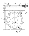
- the shaft 21 is associated with a wheel 63 arranged to cooperate with the edge 64 of the container 13.
- This wheel supported by the shaft 21, drives said container, which is supported by further idle wheels 66 and 67 associated with the grid 32 via fixed shafts 68 and 69 respectively.
- the wheels 63, 66 and 67 are positioned at the vertices of a hypothetical triangle and with the axes of rotation M, N, P lying at an angle ⁇ of 120° apart. Said wheels act as supports for the container 13 (which rests on them) and comprise a groove 63A, 66A, 67A in which the edge 64 of the container 13 is positioned when resting on said wheels.
- the support 25 and the plate or container 13 are inserted into the chamber 2 and the shaft 21 is associated with the motor 23 (or the shaft 42 with the motor 45).
- the shaft 21 moves, with the result that the plate 13 rotates about the axis W by virtue of the gear wheels 19 and 20 or the wheel 63.
- the food contained in this latter is subjected to uniform heating at least by the resistance element 11. In this manner better food preparation is achieved.
- the plate 13 When preparation is complete, the plate 13 can be easily extracted from the chamber 2 of the oven 1 to allow its easy cleaning. Particular embodiments of the invention have been described.
Landscapes
- Engineering & Computer Science (AREA)
- Food Science & Technology (AREA)
- Chemical & Material Sciences (AREA)
- Combustion & Propulsion (AREA)
- Mechanical Engineering (AREA)
- General Engineering & Computer Science (AREA)
- Electric Ovens (AREA)
- Baking, Grill, Roasting (AREA)
Claims (20)
- Four (1) comportant une chambre de cuisson (2) délimitée par des parois latérales (4, 5), une voûte (6), une paroi arrière (8) et une paroi de base (7), et des moyens d'actionnement (23, 45) pour le mouvement rotatif d'un élément de support (15, 63) pour un récipient plat (13) destiné à contenir des aliments pendant leur préparation dans le four (1), caractérisé en ce que ledit élément de support (15, 63) peut être positionné à différentes hauteurs entre la voûte (6) et la paroi de base (7) de la chambre de cuisson (2).
- Four selon la revendication 1, caractérisé en ce que l'élément de support comporte un bâti rotatif (15) supportant le récipient pour aliment (13) et associé à un arbre (21) tournant autour de son propre axe, ledit arbre et le bâti (15) tournant autour d'axes mutuellement perpendiculaires, ledit bâti (15) et ledit arbre (21) définissant un support (25) pour le récipient (13).
- Four selon la revendication 1, caractérisé en ce que l'élément de support pour le récipient (13) est un bâti (15) associé à une première roue dentée (19) prévue pour coopérer avec une deuxième roue dentée (20) associée à un arbre rotatif (21), lesdites première et deuxième roues dentées étant disposées avec un angle l'une par rapport à l'autre, ledit élément (15) et ledit arbre d'entraínement (21) définissant un support (25) pour le récipient (13).
- Four selon la revendication 3, caractérisé en ce que lesdites première et deuxième roues dentées (19, 20) sont disposées à l'intérieur d'une structure en boíte (26) de laquelle sort l'arbre rotatif (21), un axe de rotation (19) perpendiculaire au dit arbre et associé à la première roue dentée (19) et au bâti (15) supportant le récipient pour aliment (13), et un autre arbre (28) coaxial à l'arbre rotatif (21).
- Four selon la revendication 2 ou 3, caractérisé en ce que le récipient pour aliment (13) est associé de façon amovible au bâti rotatif (15).
- Four selon la revendication 2 ou 3, caractérisé en ce que le support (25) est associé à une grille (32).
- Four selon la revendication 6, caractérisé en ce que le support (25) est mobile de façon coulissante sur des supports (30) associés à la grille (32) et est amovible de cette dernière.
- Four selon la revendication 2 ou 3, caractérisé en ce que l'arbre rotatif (21) comporte des moyens (38, 42) pour son engagement en torsion avec les moyens d'actionnement (23) pour son déplacement.
- Four selon la revendication 8, caractérisé en ce que l'arbre rotatif (21) peut être associé de façon amovible aux moyens d'actionnement (23, 45).
- Four selon la revendication 1, caractérisé en ce que les moyens d'actionnement (23, 45) sont constitués par un moteur électrique, de préférence du type pas-à-pas, ledit moteur comportant un arbre de sortie (35) creux (en 36).
- Four selon les revendications 8 et 10, caractérisé en ce que l'arbre rotatif (21) a une extrémité polygonale (38) pouvant coopérer avec la cavité (36) dans l'arbre de sortie (35) du moteur électrique d'entraínement (23).
- Four selon les revendications 8 et 10, caractérisé en ce que l'arbre rotatif (21) coopère par l'intermédiaire d'éléments d'accouplement (40, 41) avec un autre arbre (42) prévu pour coopérer en torsion avec le moteur électrique d'entraínement (45) et positionné avec son axe perpendiculaire à celui de l'arbre rotatif (21).
- Four selon la revendication 12, caractérisé en ce que les moyens d'accouplement sont des roues dentées (40, 41) disposées avec un angle l'une par rapport à l'autre.
- Four selon la revendication 10, caractérisé en ce que le moteur électrique d'entraínement (23) est le moteur de tournebroche habituel.
- Four selon la revendication 10, caractérisé en ce que le moteur électrique d'entraínement (23) comporte plusieurs arbres de sortie (35) disposés à différents niveaux, le récipient (13) pouvant être positionné à différentes hauteurs à l'intérieur de la chambre de cuisson (2) en reliant de manière opérationnelle l'arbre rotatif (21) à ces différents arbres de sortie (35).
- Four selon la revendication 10, caractérisé en ce que le moteur électrique d'entraínement (45) se trouve dans une position excentrée par rapport à la paroi de chambre à proximité de laquelle il est prévu.
- Four selon la revendication 1, caractérisé en ce qu'il comporte, sur le panneau de commande (51) du four (1), un élément d'actionnement (50) destiné à commander le mouvement du récipient rotatif.
- Four selon la revendication 1, caractérisé en ce que l'élément de support mobile est une roue d'entraínement (63) associée à un arbre (21) actionné par un dispositif d'actionnement électrique (45).
- Four selon la revendication 18, caractérisé en ce que la roue d'entraínement (63) coopère avec au moins deux autres roues (66, 67) afin de supporter le récipient (13), lesdites autres roues étant de préférence folles et tournant autour d'arbres de support respectifs (68, 69) associés à une grille (32) qui peut être insérée de façon amovible dans le four (1).
- Four selon la revendication 18, caractérisé en ce que les roues (63, 66, 67) comportent une rainure (63A, 66A, 67A) dans laquelle le bord (64) du récipient plat (13) est placé, lesdits trous étant espacés de préférence d'un angle (α) de 120°.
Applications Claiming Priority (2)
| Application Number | Priority Date | Filing Date | Title |
|---|---|---|---|
| ITMI922395A IT1255890B (it) | 1992-10-19 | 1992-10-19 | Forno con piatto girevole, amovibile, in posizione distanziata da una parete inferiore della sua camera di cottura |
| ITMI922395 | 1992-10-19 |
Publications (3)
| Publication Number | Publication Date |
|---|---|
| EP0594073A2 EP0594073A2 (fr) | 1994-04-27 |
| EP0594073A3 EP0594073A3 (en) | 1995-08-23 |
| EP0594073B1 true EP0594073B1 (fr) | 1998-11-11 |
Family
ID=11364137
Family Applications (1)
| Application Number | Title | Priority Date | Filing Date |
|---|---|---|---|
| EP93116682A Expired - Lifetime EP0594073B1 (fr) | 1992-10-19 | 1993-10-15 | Four avec une plaque amovible en position séparé de la paroi inférieure de four |
Country Status (3)
| Country | Link |
|---|---|
| EP (1) | EP0594073B1 (fr) |
| DE (1) | DE69322055T2 (fr) |
| IT (1) | IT1255890B (fr) |
Families Citing this family (5)
| Publication number | Priority date | Publication date | Assignee | Title |
|---|---|---|---|---|
| US5534679A (en) * | 1994-05-20 | 1996-07-09 | Quadlux, Inc. | Apparatus for automated food handling |
| US8267257B2 (en) | 2007-03-09 | 2012-09-18 | Electrolux Home Products, Inc. | Turntable oven rack |
| TW200920259A (en) * | 2007-11-12 | 2009-05-16 | Wen-Qing Li | Efficient power-saving oven |
| ITBS20080033A1 (it) * | 2008-02-13 | 2009-08-14 | Asg International S R L | Dispositivo di cottura per forno, in particolare per la preparazione di kebab |
| US11933499B2 (en) | 2021-10-05 | 2024-03-19 | Haier Us Appliance Solutions, Inc. | Removable bottom panel for an oven appliance |
Family Cites Families (3)
| Publication number | Priority date | Publication date | Assignee | Title |
|---|---|---|---|---|
| IT8234016U1 (it) * | 1982-04-26 | 1983-10-26 | Zanussi A Spa Industrie | Griglia girevole |
| JPS58210420A (ja) * | 1982-05-31 | 1983-12-07 | Toshiba Corp | オ−ブンレンジの回転皿装置 |
| US4924763A (en) * | 1988-10-17 | 1990-05-15 | Pizza Hut | Compact pizza oven |
-
1992
- 1992-10-19 IT ITMI922395A patent/IT1255890B/it active IP Right Grant
-
1993
- 1993-10-15 DE DE69322055T patent/DE69322055T2/de not_active Expired - Fee Related
- 1993-10-15 EP EP93116682A patent/EP0594073B1/fr not_active Expired - Lifetime
Also Published As
| Publication number | Publication date |
|---|---|
| ITMI922395A1 (it) | 1994-04-19 |
| DE69322055T2 (de) | 1999-06-10 |
| IT1255890B (it) | 1995-11-17 |
| EP0594073A2 (fr) | 1994-04-27 |
| ITMI922395A0 (it) | 1992-10-19 |
| DE69322055D1 (de) | 1998-12-17 |
| EP0594073A3 (en) | 1995-08-23 |
Similar Documents
| Publication | Publication Date | Title |
|---|---|---|
| KR100793797B1 (ko) | 히팅장치 및 이를 포함하는 조리기기 | |
| US4305329A (en) | Turntable oven | |
| EP1748255B1 (fr) | Four électrique | |
| WO2008112480A1 (fr) | Grille de four à plateau tournant | |
| CN109674357B (zh) | 多功能速烤烤箱 | |
| EP1201998B1 (fr) | Four de cuisson | |
| EP0594073A2 (fr) | Four avec une plaque amovible en position séparé de la paroi inférieure de four | |
| US2348545A (en) | Roaster for stoves | |
| US8245633B2 (en) | Bread baking support and associated appliance | |
| EP1059490A2 (fr) | Four de cuisson à support de plats réglable en hauteur et procédé de fonctionnement du four | |
| US3232247A (en) | Oven assembly | |
| KR0135713B1 (ko) | 전자레인지의 출력조절장치 | |
| DE19737833A1 (de) | Gestellschiebevorrichtung für einen Gasherd | |
| CN222485954U (zh) | 一种手撕面包生产用的隧道式烤炉 | |
| US1208637A (en) | Electric cooking apparatus. | |
| US5337654A (en) | Portable oven air circulator | |
| KR102348573B1 (ko) | 멀티 가열방식의 회전 그릴장치 | |
| CN214341864U (zh) | 一种用于烤制烹饪设备的烤架及烤制烹饪设备 | |
| KR100190677B1 (ko) | 전자렌지 | |
| KR100219093B1 (ko) | 오븐레인지의 회전테이블장치 | |
| EP0174732B1 (fr) | Four à micro-ondes | |
| KR100685987B1 (ko) | 전자 레인지 | |
| JPH02102Y2 (fr) | ||
| CN215127502U (zh) | 一种带有转叉组件的电烤箱 | |
| JP2520881Y2 (ja) | 加熱調理器 |
Legal Events
| Date | Code | Title | Description |
|---|---|---|---|
| PUAI | Public reference made under article 153(3) epc to a published international application that has entered the european phase |
Free format text: ORIGINAL CODE: 0009012 |
|
| AK | Designated contracting states |
Kind code of ref document: A2 Designated state(s): DE FR GB |
|
| PUAL | Search report despatched |
Free format text: ORIGINAL CODE: 0009013 |
|
| AK | Designated contracting states |
Kind code of ref document: A3 Designated state(s): DE FR GB |
|
| 17P | Request for examination filed |
Effective date: 19960213 |
|
| 17Q | First examination report despatched |
Effective date: 19960718 |
|
| GRAG | Despatch of communication of intention to grant |
Free format text: ORIGINAL CODE: EPIDOS AGRA |
|
| GRAG | Despatch of communication of intention to grant |
Free format text: ORIGINAL CODE: EPIDOS AGRA |
|
| GRAH | Despatch of communication of intention to grant a patent |
Free format text: ORIGINAL CODE: EPIDOS IGRA |
|
| GRAH | Despatch of communication of intention to grant a patent |
Free format text: ORIGINAL CODE: EPIDOS IGRA |
|
| GRAA | (expected) grant |
Free format text: ORIGINAL CODE: 0009210 |
|
| AK | Designated contracting states |
Kind code of ref document: B1 Designated state(s): DE FR GB |
|
| REF | Corresponds to: |
Ref document number: 69322055 Country of ref document: DE Date of ref document: 19981217 |
|
| ET | Fr: translation filed | ||
| PLBE | No opposition filed within time limit |
Free format text: ORIGINAL CODE: 0009261 |
|
| STAA | Information on the status of an ep patent application or granted ep patent |
Free format text: STATUS: NO OPPOSITION FILED WITHIN TIME LIMIT |
|
| 26N | No opposition filed | ||
| PGFP | Annual fee paid to national office [announced via postgrant information from national office to epo] |
Ref country code: FR Payment date: 20011010 Year of fee payment: 9 |
|
| PGFP | Annual fee paid to national office [announced via postgrant information from national office to epo] |
Ref country code: GB Payment date: 20011017 Year of fee payment: 9 |
|
| PGFP | Annual fee paid to national office [announced via postgrant information from national office to epo] |
Ref country code: DE Payment date: 20011029 Year of fee payment: 9 |
|
| REG | Reference to a national code |
Ref country code: GB Ref legal event code: IF02 |
|
| PG25 | Lapsed in a contracting state [announced via postgrant information from national office to epo] |
Ref country code: GB Free format text: LAPSE BECAUSE OF NON-PAYMENT OF DUE FEES Effective date: 20021015 |
|
| PG25 | Lapsed in a contracting state [announced via postgrant information from national office to epo] |
Ref country code: DE Free format text: LAPSE BECAUSE OF NON-PAYMENT OF DUE FEES Effective date: 20030501 |
|
| GBPC | Gb: european patent ceased through non-payment of renewal fee |
Effective date: 20021015 |
|
| PG25 | Lapsed in a contracting state [announced via postgrant information from national office to epo] |
Ref country code: FR Free format text: LAPSE BECAUSE OF NON-PAYMENT OF DUE FEES Effective date: 20030630 |
|
| REG | Reference to a national code |
Ref country code: FR Ref legal event code: ST |