EP0594076A1 - Drallauslass - Google Patents
Drallauslass Download PDFInfo
- Publication number
- EP0594076A1 EP0594076A1 EP93116686A EP93116686A EP0594076A1 EP 0594076 A1 EP0594076 A1 EP 0594076A1 EP 93116686 A EP93116686 A EP 93116686A EP 93116686 A EP93116686 A EP 93116686A EP 0594076 A1 EP0594076 A1 EP 0594076A1
- Authority
- EP
- European Patent Office
- Prior art keywords
- outlet
- openings
- swirl
- slots
- air
- Prior art date
- Legal status (The legal status is an assumption and is not a legal conclusion. Google has not performed a legal analysis and makes no representation as to the accuracy of the status listed.)
- Granted
Links
- 241000446313 Lamella Species 0.000 claims abstract description 3
- 230000000295 complement effect Effects 0.000 description 1
- 230000006698 induction Effects 0.000 description 1
- 238000000034 method Methods 0.000 description 1
- 238000004080 punching Methods 0.000 description 1
- 238000003466 welding Methods 0.000 description 1
Images
Classifications
-
- F—MECHANICAL ENGINEERING; LIGHTING; HEATING; WEAPONS; BLASTING
- F24—HEATING; RANGES; VENTILATING
- F24F—AIR-CONDITIONING; AIR-HUMIDIFICATION; VENTILATION; USE OF AIR CURRENTS FOR SCREENING
- F24F13/00—Details common to, or for air-conditioning, air-humidification, ventilation or use of air currents for screening
- F24F13/02—Ducting arrangements
- F24F13/06—Outlets for directing or distributing air into rooms or spaces, e.g. ceiling air diffuser
Definitions
- the invention relates to a swirl outlet with an outlet disk, in which star-shaped outlet slots are formed, each of which is assigned an air guide lamella.
- Such swirl outlets are known in many forms and designs. Reference is made here, for example, to DE-OS 40 26 932.9. Bearing disks, such as are shown, for example, in DE-OS 38 32 052.5, are generally used to fix the air guide vanes.
- the object of the present invention is to further improve these swirl outlets and to increase the amount of air to be introduced.
- openings are provided in and / or around the outlet slots in the outlet disk.
- the fluidic connection between the air guide fins and the openings is also important.
- the air flows through the openings more or less deeply vertically into a room.
- the air guide fins give the air flow, which emerges from the outlet slots, a swirl, which engages in the vertical air flow of the openings and deflects them. This significantly improves the induction into the room.
- the openings are not only arranged between the outlet slots, but there is a ring of openings around the outlet slots. If the outlet disc is round, this ring is also round. However, an angular configuration is also conceivable, depending on how the outlet disk is shaped. It is essential that the outer ring of openings creates a kind of cylindrical air curtain in which the swirled air can be introduced deep into a room. In this way, warm air in particular can be introduced very deeply into a room before the targeted guidance is canceled and then the warm air is distributed and rises again.
- the majority of the openings between the outlet slots are formed with a relatively small diameter, while the openings in the ring around the outlet slots have a larger diameter.
- the air flows through the outlet slots more freely, so that the sufficient swirl can be given to it.
- the openings in the ring around the outlet slots also allow the air to enter the room more freely.
- the air emerging from the openings with a smaller diameter is carried away by the swirl flow, but pulls the swirl flow down into the room. From this it can be seen that the individual different air flows complement each other effectively.
- a swirl outlet R according to the invention has gem.
- outlet slots 5 are formed in the outlet disk 1.
- these outlet slots 5 have different lengths 1 1 and 1 2 .
- the openings 6 do not all have the same diameter, but can be shaped differently. All of these shapes and differences in shape are intended to be encompassed by the present inventive concept.
- 5 slats 7 are assigned to the outlet slots. These slats 7 are preferably rotatably mounted on an axis 8, the axis 8 extending between two bearing disks 9 and 10.
- the bearing disks 9 and 10 can be punched out of the material of the outlet disk 1 during the punching process for the outlet slots 5 and bent upwards. Other definitions for the bearing disc are also within the scope of the invention. However, the bearing disks preferably have one Footbridge 11, which forms a groove 12 or 13 on both sides towards the bearing disk 9 or 10. To fix the bearing disk 9 or 10 in the outlet slot 5, the bearing disk 9 or 10 can then be inserted into the outlet slot 5 and rotated until the marginal edges of the outlet slot 5 each enter the groove 12 or 13. As a result, the setting of the fins 7 is simplified, and no additional welding spots or the like are. Fixings needed.
Landscapes
- Engineering & Computer Science (AREA)
- Combustion & Propulsion (AREA)
- Mechanical Engineering (AREA)
- General Engineering & Computer Science (AREA)
- Chemical & Material Sciences (AREA)
- Air-Flow Control Members (AREA)
- Cyclones (AREA)
- Duct Arrangements (AREA)
- Cooling Or The Like Of Electrical Apparatus (AREA)
- Percussion Or Vibration Massage (AREA)
- Treatment Of Fiber Materials (AREA)
- Pharmaceuticals Containing Other Organic And Inorganic Compounds (AREA)
- Professional, Industrial, Or Sporting Protective Garments (AREA)
- Multiple-Way Valves (AREA)
- Grinding-Machine Dressing And Accessory Apparatuses (AREA)
Abstract
Description
- Die Erfindung betrifft einen Drallauslaß mit einer Auslaßscheibe, in welche sternförmig angeordnete Auslaßschlitze eingeformt sind, denen jeweils eine Luftleitlamelle zugeordnet ist.
- Derartige Drallauslässe sind in vielfältiger Form und Ausführung bekannt. Verwiesen wird hier beispielsweise auf die DE-OS 40 26 932.9. Zur Festlegung der Luftleitlamellen dienen in der Regel Lagerscheiben, wie sie beispielsweise in der DE-OS 38 32 052.5 dargestellt sind.
- Derartige Drallauslässe haben sich zum Einbringen von Warm- und/oder Kaltluft bestens bewährt, allerdings ist die Menge der in einen Raum einzubringenden Luft durch die Anzahl und Größe der Auslaßschlitze begrenzt.
- Dervorliegenden Erfindung liegt die Aufgabe zugrunde, diese Drallauslässe noch weiter zu verbessern und die Menge der einzubringenden Luft zu erhöhen.
- Zur Lösung dieser Aufgabe führt, daß zwischen und/oder um die Auslaßschlitze Durchbrüche in der Auslaßscheibe vorgesehen sind.
- Bei einem derartigen Auslaß wird durch die Auslaßscheibe ein gewisser Vordruck aufgebaut, so daß die Luft nicht nur durch die Auslaßschlitze sondern insbesondere auch durch die Durchbrüche nach außen strömt. D.h., aus der gesamten Auslaßscheibe strömt Luft und zwar in unterschiedlichen Richtungen. Dadurch wird der freie Querschnitt der Luftaustrittsöffnungen erheblich erhöht, und es kann über einen einzigen Auslaß wesentlich mehr Luft einem Raum zugeführt werden.
- Wesentlich ist aber auch die strömungstechnische Verbindung zwischen den Luftleitlamellen und den Durchbrüchen. Je nach dem Vordruck vor der Auslaßscheibe strömt durch die Durchbrüche die Luft mehr oder weniger tief senkrecht in einen Raum ein. Dagegen geben die Luftleitlamellen der Luftströmung, welche aus den Auslaßschlitzen austritt, einen Drall mit, welcher in die senkrechte Luftströmung der Durchbrüche eingreift und diese umlenkt. Hierdurch wird die Induktion in den Raum wesentlich verbessert.
- In einem bevorzugten Ausführungsbeispiel der Erfindung sind nicht nur zwischen den Auslaßschlitzen die Durchbrüche angeordnet, sondern es befindet sich ein Ring von Durchbrüchen um die Auslaßschlitze herum. Sofern die Auslaßscheibe rund geformt ist, ist dieser Ring ebenfalls rund. Jedoch ist auch eine eckige Ausgestaltung denkbar, je nachdem, wie die Auslaßscheibe geformt ist. Wesentlich ist dabei, daß der äußere Ring von Durchbrüchen quasi einen zylinderförmigen Luftschleier erzeugt, in welchem die mit einem Drall versehene Luft tief in einen Raum eingeführt werden kann. Auf diese Weise kann insbesondere Warmluft sehr tief in einen Raum eingeführt werden, bevor die gezielte Führung aufgehoben wird und sich dann die warme Luft verteilt und wieder nach oben steigt.
- Um eine gute und gewollte Steuerung der Luftströmung zu erreichen, hat es sich als günstig erwiesen, wenn der größte Teil der Durchbrüche zwischen den Auslaßschlitzen mit einem relativ geringen Durchmesser geformt ist, während die Durchbrüche im Ring um die Auslaßschlitze einen größeren Durchmesser aufweisen. Bei einem gleichen Vordruck vor der Auslaßscheibe strömt die Luft durch die Auslaßschlitze freier, so daß ihr der genügende Drall mitgegeben werden kann. Auch durch die Durchbrüche im Ring um die Auslaßschlitze kann die Luft freier in den Raum eintreten. Die aus den Durchbrüchen mit einem geringeren Durchmesser austretende Luft wird dagegen von der Drallströmung mitgerissen, zieht jedoch die Drallströmung nach unten in den Raum. Daraus ist ersichtlich, daß sich die einzelnen unterschiedlichen Luftströmungen wirkungsvoll ergänzen.
- Weitere Vorteile, Merkmale und Einzelheiten der Erfindung ergeben sich aus der nachfolgenden Beschreibung bevorzugter Ausführungsbeispiele sowie anhand der Zeichnung; diese zeigt in
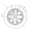
- Fig. 1 eine Draufsicht auf einen erfindungsgemäßen Drallauslaß;
- Fig. 2 einen Querschnitt durch den Drallauslaß gem. Fig. 1 entlang Linie 11 - II.
- Ein erfindungsgemäßer Drallauslaß R weist gem. den Figuren 1 und 2 eine Auslaßscheibe 1 auf, welche von einem trichterförmig nach außen gewölbten Randstreifen 2 umfangen ist. In Gebrauchslage liegt dieser trichterförmige Randstreifen 2 mit seiner Außenkante 3 einer Decke 4 von unten her an.
- In die Auslaßscheibe 1 sind zum einen rechteckförmige Auslaßschlitze 5 eingeformt. Im vorliegenden Ausführungsbeispiel weisen diese Auslaßschlitze 5 unterschiedliche Längen 11 und 12 auf. Zum anderen befinden sich in der Auslaßscheibe zwischen den Auslaßschlitzen 5 viele relativ kleine Durchbrüche 6, welche im vorliegenden Ausführungsbeispiel als runde Löcher geformt sind. Im Rahmen der Erfindung liegen jedoch alle anderen geometrischen Formen, beispielsweise eckige, elipsenförmige, tropfenförmige usw. Löcher. Ferner ist erkennbar, daß die Durchbrüche 6 nicht alle den gleichen Durchmesser haben, sondern unterschiedlich geformt sein können. Sämtliche dieser Formen und Formunterschiede sollen vom vorliegenden Erfindungsgedanken umfaßt sein.
- Ferner ist insbesondere in Fig. 2 erkennbar, daß den Auslaßschlitzen 5 Lamellen 7 zugeordnet sind. Bevorzugt sind diese Lamellen 7 drehbar an einer Achse 8 gelagert, wobei sich die Achse 8 zwischen zwei Lagerscheiben 9 und 10 erstreckt.
- Die Lagerscheiben 9 und 10 können während des StanzvorgangesfürdieAuslaßschlitze 5 aus dem Material der Auslaßscheibe 1 herausgestanzt und nach oben abgebogen sein. Im Rahmen der Erfindung liegen auch andere Festlegungen für die Lagerscheibe. Bevorzugt weisen jedoch die Lagerscheiben einen Fußsteg 11 auf, welcher zur Lagerscheibe 9 bzw. 10 hin beidsseits eine Nut 12 bzw. 13 ausformt. Zum Festlegen der Lagerscheibe 9 bzw. 10 in dem Auslaßschlitz 5 kann dann die Lagerscheibe 9 bzw. 10 in den Auslaßschlitz 5 eingesetzt und gedreht werden, bis die Randkanten des Auslaßschlitzes 5 jeweils in die Nut 12 bzw. 13 einfahren. Hierdurch ist das Festlegen der Lamellen 7 vereinfacht, und es werden keine zusätzlichen Schweißpunkte od.dgl. Befestigungen benötigt.
Claims (7)
dadurch gekennzeichnet,
daß zwischen und/oder um die Auslaßschlitze (5) Durchbrüche (6) in der Auslaßscheibe (1) vorgesehen sind.
Applications Claiming Priority (2)
| Application Number | Priority Date | Filing Date | Title |
|---|---|---|---|
| DE9214369U DE9214369U1 (de) | 1992-10-23 | 1992-10-23 | Drallauslaß |
| DE9214369U | 1992-10-23 |
Publications (2)
| Publication Number | Publication Date |
|---|---|
| EP0594076A1 true EP0594076A1 (de) | 1994-04-27 |
| EP0594076B1 EP0594076B1 (de) | 1996-01-31 |
Family
ID=6885176
Family Applications (1)
| Application Number | Title | Priority Date | Filing Date |
|---|---|---|---|
| EP93116686A Expired - Lifetime EP0594076B1 (de) | 1992-10-23 | 1993-10-15 | Drallauslass |
Country Status (8)
| Country | Link |
|---|---|
| EP (1) | EP0594076B1 (de) |
| AT (1) | ATE133774T1 (de) |
| CZ (1) | CZ225193A3 (de) |
| DE (2) | DE9214369U1 (de) |
| ES (1) | ES2082574T3 (de) |
| HU (1) | HUT65570A (de) |
| PL (1) | PL300827A1 (de) |
| SK (1) | SK117393A3 (de) |
Cited By (3)
| Publication number | Priority date | Publication date | Assignee | Title |
|---|---|---|---|---|
| DE4405630A1 (de) * | 1994-02-22 | 1995-08-24 | Schako Metallwarenfabrik | Deckenauslaß |
| WO1995023318A1 (de) * | 1994-02-23 | 1995-08-31 | Schako Metallwarenfabrik Ferdinand Schad Kg | Drallauslass |
| EP2322867A1 (de) | 2009-11-11 | 2011-05-18 | TROX GmbH | Auslass, insbesondere Drallauslass, zur Belüftung von Räumen |
Families Citing this family (3)
| Publication number | Priority date | Publication date | Assignee | Title |
|---|---|---|---|---|
| DE4305471C2 (de) * | 1993-02-24 | 1997-06-19 | Fritz Juergen Eidmann | Deckenluftauslaß, insbesondere Luftauslaßschiene |
| DE9303880U1 (de) * | 1993-03-19 | 1993-06-03 | "Schako" Metallwarenfabrik Ferdinand Schad KG Zweigniederlassung Kolbingen, 7201 Kolbingen | Düsenauslaß |
| DE4416841C2 (de) * | 1994-05-13 | 1997-10-23 | Mueller Erwin Gmbh & Co | Luftauslaß, insbesondere Deckenluftauslaß |
Citations (5)
| Publication number | Priority date | Publication date | Assignee | Title |
|---|---|---|---|---|
| GB2120778A (en) * | 1982-05-20 | 1983-12-07 | Howorth Air Eng Ltd | Outlet device for an air conditioning system |
| US4955286A (en) * | 1988-07-01 | 1990-09-11 | Schako Metallwarenfabrik Ferdinand Schad Ag | Turbulence outlet |
| DE4026932A1 (de) * | 1990-08-25 | 1992-04-30 | Schako Metallwarenfabrik | Deckenauslass |
| US5120274A (en) * | 1988-03-18 | 1992-06-09 | Schako Metallwarenfabrik Ferdinand Schad Kg | Ceiling outlet |
| DE4140208C1 (en) * | 1991-12-05 | 1993-05-19 | Erwin Mueller Gmbh & Co, 4450 Lingen, De | Ventilating and air conditioning air outlet - has adjustable slats hingeably mounted on corresp. edge of front plate apertures |
Family Cites Families (3)
| Publication number | Priority date | Publication date | Assignee | Title |
|---|---|---|---|---|
| DE2838400C2 (de) * | 1978-09-02 | 1982-09-23 | Schako Metallwarenfabrik Ferdinand Schad Gmbh, Zweigniederlassung Kolbingen, 7201 Kolbingen | Luftauslaß zur Belüftung von Räumen |
| DE3042216C2 (de) * | 1980-11-08 | 1986-03-27 | H. Krantz Gmbh & Co, 5100 Aachen | Drallauslaß |
| DE4116481A1 (de) * | 1991-05-21 | 1992-11-26 | Schako Metallwarenfabrik | Luftauslass |
-
1992
- 1992-10-23 DE DE9214369U patent/DE9214369U1/de not_active Expired - Lifetime
-
1993
- 1993-10-15 EP EP93116686A patent/EP0594076B1/de not_active Expired - Lifetime
- 1993-10-15 ES ES93116686T patent/ES2082574T3/es not_active Expired - Lifetime
- 1993-10-15 AT AT93116686T patent/ATE133774T1/de not_active IP Right Cessation
- 1993-10-15 DE DE59301549T patent/DE59301549D1/de not_active Expired - Fee Related
- 1993-10-22 CZ CZ932251A patent/CZ225193A3/cs unknown
- 1993-10-22 HU HU9302993A patent/HUT65570A/hu unknown
- 1993-10-22 PL PL93300827A patent/PL300827A1/xx unknown
- 1993-10-25 SK SK1173-93A patent/SK117393A3/sk unknown
Patent Citations (5)
| Publication number | Priority date | Publication date | Assignee | Title |
|---|---|---|---|---|
| GB2120778A (en) * | 1982-05-20 | 1983-12-07 | Howorth Air Eng Ltd | Outlet device for an air conditioning system |
| US5120274A (en) * | 1988-03-18 | 1992-06-09 | Schako Metallwarenfabrik Ferdinand Schad Kg | Ceiling outlet |
| US4955286A (en) * | 1988-07-01 | 1990-09-11 | Schako Metallwarenfabrik Ferdinand Schad Ag | Turbulence outlet |
| DE4026932A1 (de) * | 1990-08-25 | 1992-04-30 | Schako Metallwarenfabrik | Deckenauslass |
| DE4140208C1 (en) * | 1991-12-05 | 1993-05-19 | Erwin Mueller Gmbh & Co, 4450 Lingen, De | Ventilating and air conditioning air outlet - has adjustable slats hingeably mounted on corresp. edge of front plate apertures |
Cited By (3)
| Publication number | Priority date | Publication date | Assignee | Title |
|---|---|---|---|---|
| DE4405630A1 (de) * | 1994-02-22 | 1995-08-24 | Schako Metallwarenfabrik | Deckenauslaß |
| WO1995023318A1 (de) * | 1994-02-23 | 1995-08-31 | Schako Metallwarenfabrik Ferdinand Schad Kg | Drallauslass |
| EP2322867A1 (de) | 2009-11-11 | 2011-05-18 | TROX GmbH | Auslass, insbesondere Drallauslass, zur Belüftung von Räumen |
Also Published As
| Publication number | Publication date |
|---|---|
| PL300827A1 (en) | 1994-05-16 |
| SK117393A3 (en) | 1994-09-07 |
| EP0594076B1 (de) | 1996-01-31 |
| ES2082574T3 (es) | 1996-03-16 |
| DE59301549D1 (de) | 1996-03-14 |
| HU9302993D0 (en) | 1994-01-28 |
| ATE133774T1 (de) | 1996-02-15 |
| DE9214369U1 (de) | 1993-02-04 |
| CZ225193A3 (en) | 1994-05-18 |
| HUT65570A (en) | 1994-07-28 |
Similar Documents
| Publication | Publication Date | Title |
|---|---|---|
| EP0931198B1 (de) | Strahlregler | |
| DE69322625T2 (de) | Düse und verfahren zur belüftung | |
| DE10292792B4 (de) | Klimatisierungskanal für ein Fahrzeug | |
| EP1287208A1 (de) | Strahlregler | |
| EP4058640B1 (de) | Strahlregler | |
| DE102017115012B3 (de) | Belüftungskanal für eine Lüftungsvorrichtung eines Kraftfahrzeugs | |
| DE4037287C2 (de) | Auslaß | |
| EP0335151B1 (de) | Luftauslass zur Erzeugung einer turbulenzarmen Verdrängungsströmung | |
| EP0594076B1 (de) | Drallauslass | |
| EP0360147B1 (de) | Drallauslass | |
| DE202019101313U1 (de) | Strahlregler | |
| DE60312410T2 (de) | Klimaanlage mit einem Gitter mit verminderter Geräuschentwicklung | |
| WO2021069191A1 (de) | Sanitäres einbauteil und baureihe für ein sanitäres einbauteil | |
| AT523395A4 (de) | Vorrichtung zum Beduften eines Raumes | |
| DE19626884C2 (de) | Luftauslaß | |
| DD297226A5 (de) | Induktivdurchlass | |
| DE4405738C1 (de) | Drallauslaß | |
| DE4405630C2 (de) | Deckenauslaß | |
| EP0567795A1 (de) | Luftauslass | |
| EP0239854B1 (de) | Luftauslass | |
| DE69105947T2 (de) | Lüftungsanlage. | |
| DE102013206872A1 (de) | Lüftungsdüse | |
| DE69407707T2 (de) | Aufhängegerippe für eine aufgehängte Decke | |
| DE1291694B (de) | Vorrichtung zum Belueften von unter Druck aus einem Zapfhahn fliessendem Wasser | |
| WO1995014892A1 (de) | Verfahren zum herstellen eines schlitzauslasses |
Legal Events
| Date | Code | Title | Description |
|---|---|---|---|
| PUAI | Public reference made under article 153(3) epc to a published international application that has entered the european phase |
Free format text: ORIGINAL CODE: 0009012 |
|
| AK | Designated contracting states |
Kind code of ref document: A1 Designated state(s): AT BE CH DE DK ES FR GB GR IE IT LI LU MC NL PT SE |
|
| 17P | Request for examination filed |
Effective date: 19940705 |
|
| 17Q | First examination report despatched |
Effective date: 19950707 |
|
| GRAA | (expected) grant |
Free format text: ORIGINAL CODE: 0009210 |
|
| AK | Designated contracting states |
Kind code of ref document: B1 Designated state(s): AT BE CH DE DK ES FR GB GR IE IT LI LU MC NL PT SE |
|
| PG25 | Lapsed in a contracting state [announced via postgrant information from national office to epo] |
Ref country code: GR Free format text: LAPSE BECAUSE OF FAILURE TO SUBMIT A TRANSLATION OF THE DESCRIPTION OR TO PAY THE FEE WITHIN THE PRESCRIBED TIME-LIMIT Effective date: 19960131 Ref country code: DK Effective date: 19960131 |
|
| REF | Corresponds to: |
Ref document number: 133774 Country of ref document: AT Date of ref document: 19960215 Kind code of ref document: T |
|
| ET | Fr: translation filed | ||
| REG | Reference to a national code |
Ref country code: IE Ref legal event code: FG4D Free format text: 67104 |
|
| REF | Corresponds to: |
Ref document number: 59301549 Country of ref document: DE Date of ref document: 19960314 |
|
| REG | Reference to a national code |
Ref country code: ES Ref legal event code: FG2A Ref document number: 2082574 Country of ref document: ES Kind code of ref document: T3 |
|
| REG | Reference to a national code |
Ref country code: CH Ref legal event code: NV Representative=s name: BRYNJULV LEGLAND |
|
| ITF | It: translation for a ep patent filed | ||
| PG25 | Lapsed in a contracting state [announced via postgrant information from national office to epo] |
Ref country code: SE Effective date: 19960430 Ref country code: PT Effective date: 19960430 |
|
| GBT | Gb: translation of ep patent filed (gb section 77(6)(a)/1977) |
Effective date: 19960423 |
|
| PG25 | Lapsed in a contracting state [announced via postgrant information from national office to epo] |
Ref country code: IE Free format text: LAPSE BECAUSE OF NON-PAYMENT OF DUE FEES Effective date: 19960815 |
|
| REG | Reference to a national code |
Ref country code: IE Ref legal event code: FD4D Ref document number: 67104 Country of ref document: IE |
|
| PG25 | Lapsed in a contracting state [announced via postgrant information from national office to epo] |
Ref country code: AT Effective date: 19961015 |
|
| PG25 | Lapsed in a contracting state [announced via postgrant information from national office to epo] |
Ref country code: ES Free format text: LAPSE BECAUSE OF NON-PAYMENT OF DUE FEES Effective date: 19961016 |
|
| PG25 | Lapsed in a contracting state [announced via postgrant information from national office to epo] |
Ref country code: LU Free format text: LAPSE BECAUSE OF NON-PAYMENT OF DUE FEES Effective date: 19961031 Ref country code: LI Effective date: 19961031 Ref country code: CH Effective date: 19961031 Ref country code: BE Effective date: 19961031 |
|
| PLBE | No opposition filed within time limit |
Free format text: ORIGINAL CODE: 0009261 |
|
| STAA | Information on the status of an ep patent application or granted ep patent |
Free format text: STATUS: NO OPPOSITION FILED WITHIN TIME LIMIT |
|
| 26N | No opposition filed | ||
| BERE | Be: lapsed |
Owner name: SCHAKO METALLWARENFABRIK FERDINAND SCHAD K.G. Effective date: 19961031 |
|
| PG25 | Lapsed in a contracting state [announced via postgrant information from national office to epo] |
Ref country code: MC Effective date: 19970430 |
|
| REG | Reference to a national code |
Ref country code: CH Ref legal event code: PL |
|
| PG25 | Lapsed in a contracting state [announced via postgrant information from national office to epo] |
Ref country code: FR Effective date: 19970630 |
|
| REG | Reference to a national code |
Ref country code: FR Ref legal event code: ST |
|
| PG25 | Lapsed in a contracting state [announced via postgrant information from national office to epo] |
Ref country code: GB Free format text: LAPSE BECAUSE OF NON-PAYMENT OF DUE FEES Effective date: 19971015 |
|
| PG25 | Lapsed in a contracting state [announced via postgrant information from national office to epo] |
Ref country code: NL Free format text: LAPSE BECAUSE OF NON-PAYMENT OF DUE FEES Effective date: 19980501 |
|
| GBPC | Gb: european patent ceased through non-payment of renewal fee |
Effective date: 19971015 |
|
| NLV4 | Nl: lapsed or anulled due to non-payment of the annual fee |
Effective date: 19980501 |
|
| REG | Reference to a national code |
Ref country code: ES Ref legal event code: FD2A Effective date: 19971112 |
|
| PG25 | Lapsed in a contracting state [announced via postgrant information from national office to epo] |
Ref country code: IT Free format text: LAPSE BECAUSE OF NON-PAYMENT OF DUE FEES;WARNING: LAPSES OF ITALIAN PATENTS WITH EFFECTIVE DATE BEFORE 2007 MAY HAVE OCCURRED AT ANY TIME BEFORE 2007. THE CORRECT EFFECTIVE DATE MAY BE DIFFERENT FROM THE ONE RECORDED. Effective date: 20051015 |
|
| PGFP | Annual fee paid to national office [announced via postgrant information from national office to epo] |
Ref country code: DE Payment date: 20051227 Year of fee payment: 13 |
|
| PG25 | Lapsed in a contracting state [announced via postgrant information from national office to epo] |
Ref country code: DE Free format text: LAPSE BECAUSE OF NON-PAYMENT OF DUE FEES Effective date: 20070501 |