EP0594090A1 - Dispositif de positionnement d'objets - Google Patents
Dispositif de positionnement d'objets Download PDFInfo
- Publication number
- EP0594090A1 EP0594090A1 EP93116757A EP93116757A EP0594090A1 EP 0594090 A1 EP0594090 A1 EP 0594090A1 EP 93116757 A EP93116757 A EP 93116757A EP 93116757 A EP93116757 A EP 93116757A EP 0594090 A1 EP0594090 A1 EP 0594090A1
- Authority
- EP
- European Patent Office
- Prior art keywords
- alignment
- engagement
- piece goods
- good
- running
- Prior art date
- Legal status (The legal status is an assumption and is not a legal conclusion. Google has not performed a legal analysis and makes no representation as to the accuracy of the status listed.)
- Granted
Links
- 230000033001 locomotion Effects 0.000 claims abstract description 44
- 238000012546 transfer Methods 0.000 claims abstract description 5
- 230000001360 synchronised effect Effects 0.000 claims description 3
- 230000007704 transition Effects 0.000 claims description 3
- 238000005452 bending Methods 0.000 claims 1
- 239000000969 carrier Substances 0.000 claims 1
- 238000006073 displacement reaction Methods 0.000 claims 1
- 238000004806 packaging method and process Methods 0.000 abstract description 3
- 239000013598 vector Substances 0.000 description 4
- 238000013459 approach Methods 0.000 description 3
- 238000013461 design Methods 0.000 description 3
- 239000000463 material Substances 0.000 description 3
- 230000007423 decrease Effects 0.000 description 2
- 238000012545 processing Methods 0.000 description 2
- 230000001154 acute effect Effects 0.000 description 1
- 230000005540 biological transmission Effects 0.000 description 1
- 238000009459 flexible packaging Methods 0.000 description 1
- 238000009434 installation Methods 0.000 description 1
- 230000001788 irregular Effects 0.000 description 1
- 239000007769 metal material Substances 0.000 description 1
- 238000000034 method Methods 0.000 description 1
- 230000002093 peripheral effect Effects 0.000 description 1
- 230000000284 resting effect Effects 0.000 description 1
- 230000003068 static effect Effects 0.000 description 1
Images
Classifications
-
- B—PERFORMING OPERATIONS; TRANSPORTING
- B65—CONVEYING; PACKING; STORING; HANDLING THIN OR FILAMENTARY MATERIAL
- B65H—HANDLING THIN OR FILAMENTARY MATERIAL, e.g. SHEETS, WEBS, CABLES
- B65H31/00—Pile receivers
- B65H31/34—Apparatus for squaring-up piled articles
Definitions
- the invention relates to a positioning device with which piece goods in a predetermined movement path or a fixed position z. B. can be provided so that it is aligned with one, two or three orthogonal spatial axes with respect to a reference plane or a reference point or a base.
- General cargo seen in at least one of the spatial axes, can have an irregular or regular rounded or angular shape, in particular an external shape, for example triangular, rectangular, square and similar.
- the piece goods can be deformable, at least when they are in contact with a base area, and are essentially incompressible, but essentially deformable parallel to the base area, but can be deformed, as is the case, for example, with piece goods consisting of a large number of the same size and flush with one another in a stack
- Leaf layers is the case which can be shifted against each other parallel to their planes or can be lifted off each other transversely to their planes
- the piece goods form a strictly rectangular cuboid, which can be highly resistant to deformation, although its individual layers have thicknesses of less than two or one tenth of a millimeter and are essential in the case of paper or paper-like materials higher flexibility than e.g. metallic materials have approximately the same dimensions.
- General cargo is aligned especially for the purpose of subsequent processing.
- the piece goods are aligned with a packaging station, in which they are brought together in a precisely predetermined position with a flexible packaging wrapping that is still essentially spread out and this is then wrapped around the piece goods.
- This can e.g. in that the piece goods are aligned between box-shaped walls and their four sides can slide transversely to a base surface and at right angles and parallel to each other on the inside walls.
- Another object of the invention is to provide a positioning device in which disadvantages of known designs or of the type described are avoided and which ensures an increased working speed, in particular when the piece goods are subjected to low loads.
- the alignment can take place in that alignment surfaces act on narrowly delimited zones of the piece goods and thereby introduce alignment forces into the piece goods, each approximately parallel to one, two or three of the spatial axes can act in opposite directions after deviation from the desired alignment state.
- Two or three alignment movements approximately at right angles to one another or parallel to the spatial axes are advantageously superimposed on one another in such a way that a reduction ratio between 5: 1 and 18: 1, in particular between 10: 1 and 14: 1, exists between at least two alignment movements with regard to the movement path , where, depending on the level of the alignment resistances between these limit values, any integer multiple can be advantageous.
- the alignment along the relatively longer movement path can simultaneously serve to transport the piece goods, for example to an aligned ready position determined by the stop and / or interruption of the drive. Simultaneously with this conveying movement, the general cargo is then aligned in a direction transverse to it by a relatively much smaller path and, if necessary, in a further direction transverse to both of the aforementioned directions by a relatively even smaller path, namely transverse to its base surface.
- This last alignment can be done in a simple manner in that the piece goods are pushed with their base surface onto a correspondingly aligned base surface.
- the alignment base does not have to be moved relative to the device base, but the piece goods can be moved and thereby simultaneously transferred from one station, for example a stacking picture, to another work station, in which it then moves to the base area after two about parallel spatial axes arrives exactly aligned and is stopped.
- the alignment movements are advantageously not in a vertical, but in a different, e.g. approximately horizontal direction, the base advantageously deviating from a vertical position, namely as a wing for receiving the weight on the underside of the piece goods.
- two alignment movements are expediently approximately parallel to this direction or plane or, in the case of stack layers, parallel to their planes.
- the alignment surfaces advantageously attack uniformly over the entire extent of the piece goods that lies transversely to the planes mentioned.
- the alignment surfaces are brought into engagement with the associated counter surfaces of the piece goods over its entire associated extent essentially simultaneously by transverse movements.
- the respective alignment surface can be tilted at least by a few angular degrees about an axis that is approximately parallel to it or approximately perpendicular and at most at a short distance from it, so that it automatically adjusts itself to an essentially full-surface position under the contact forces can and not only lies in point or line form on the piece goods.
- the alignment surface can be deflected at least over part of its travel in a direction away from the piece goods against a restoring force, so that it acts relatively softly on the piece goods. It is only at the end of their travel that the alignment surface is expediently or positively supported against such deflection movements, so that the general cargo is in any case forced into its predetermined alignment position in this last phase. In this last phase, the alignment surface can move outward on an arch path, by means of which the reduction ratio mentioned is reduced in this last phase.
- a particularly fast way of working can be achieved if the alignment surfaces take over the respective piece goods from a conveyor running at a uniform speed, which expediently forms a substantially continuous continuation of the base area and on which the piece goods can then be roughly pre-aligned transversely to the conveying direction before it slides onto the actual base area.
- the alignment surfaces can have a higher conveying speed than the conveyor, so that they catch up the piece goods in the manner of sliders on the back and after running onto the piece goods, they move them at a correspondingly higher speed relative to the transporter and the subsequent piece goods.
- the alignment surfaces are then stopped, so that they continue to secure the piece goods and form a slide guide lying transversely to the base area, along which the piece goods can be transferred to the processing position of the associated work station.
- the following piece goods are conveyed further at the same speed, the intermediate distances between successive piece goods being selected such that the alignment surfaces of the piece goods transferred into the working position are already released before they have to be moved again in order to take over a subsequent piece goods.
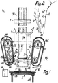
- the positioning device 1 is used to feed piece goods 2, e.g. Paper giant of at least one or more 100 sheets each, to a work station in which the piece goods 2 arrive precisely aligned in view of their underside or base surface 3, so that the work station associated with the work station can be carried out by moving them at right angles to their base surface.
- the piece goods 2 have, at right angles to the flat base surface 3 in pairs opposite one another and at right angles to one another, flat side surfaces 4 to 7 which adjoin one another in right-angled corner zones.
- the base surface 3 is parallel to a flat top surface 8 of the same size.
- the device 1 has, for example, a frame-like device base 9, which determines an alignment base 10, against which the respective piece goods 2 are to assume a more precisely determined, fixed position, both in plan view and in view of each side surface 4 to 7.
- the height is determined by an essentially flat base surface 11, on which the piece goods 2 rests with the base surface 3.
- a precise alignment transversely to the side surfaces 6, 7 is determined by a continuously flat alignment surface 12, which is used for the full-surface contact of the side surface 6 and in a view of the base surface 11 at a distance of this lies, which can be in the order of a third of the distance between the side surfaces 6, 7.
- the alignment surface 12 is opposite to approximately parallel and planar alignment surfaces 14, which are intended for the installation of the side surface 7 with areas that correspond to only half to a twelfth, in particular a fifth to a tenth, of the total surface area of the side surface 7 .
- Each alignment surface 14 is directly adjoined in a rigid assignment by an approximately flat, also flat alignment surface 13, which is intended for contacting the associated side surface 4 or 5 with an area component which can also be of the order of magnitude mentioned.
- Alignment surfaces 13 are provided only at a distance from the alignment surface 12, namely in the region of the corner zone of the piece goods 2 delimited by the side surface 7, so that this does not directly adhere to the side surfaces 4, 5 over most of its extent between the side surfaces 6, 7 Alignment surfaces. All alignment surfaces 12 to 14 extend at least over the total height of the piece goods 2.
- At least one, namely the alignment surface 12, is larger than the associated side surface 6, so that it protrudes beyond the base surface 3, the top surface 8 and / or the side surface 4 or 5 and the side surface 6 rests essentially over its entire surface.
- the alignment surface 12 is formed by a plate surface of a plate-shaped alignment body 15, which is advantageously essentially vertical.
- a pair of two alignment surfaces 13, 14 delimiting a protruding corner zone is formed by an alignment body 16 or 17 which is angular in cross section, which is designed as an angularly continuous profile bar which is constant over its entire length and is approximately at right angles to the base surface 11 or extends approximately parallel to the alignment surface 12.
- the angle leg forming the wider alignment surface 13 is longer than the angle leg forming the narrower alignment surface 14.
- Each alignment surface 14 lies in a top view with a lateral distance from the base surface 11, while each alignment surface 13 lies in the ready position with a considerably greater distance from the alignment surface 12.
- the angle between the alignment surfaces 13, 14 essentially corresponds exactly to the angle between the associated side surfaces 4, 7 and 5, 7 in the region of the corner zone of the piece goods 2.
- the alignment surface 12 is not moved by a direct drive or is arranged essentially stationary, while the alignment surfaces 13, 14 can each be moved transversely against the alignment surface 12 by the drive with the piece goods 2.
- the respective alignment body 16 or 17 is fastened to two essentially identical support members 18 which are spaced apart from one another transversely to the base surface 11 or parallel to the alignment surface 12 and in the longitudinal direction of which the respective alignment body 16 or 17 is essentially rigid or is positively attached.
- the support members 18 are expediently formed by roller chains, toothed belts or the like. So that they can be driven without slippage.
- the strand 19 of each support element 18 facing the piece goods 2 lies in a view of the base surface 11 according to FIG. 1 at an acute angle of less than 30, 20, 15 or 10 ° with respect to a plane or plane approximately perpendicular to the surfaces 11, 12 or to the associated side surface 4 or 5 and approaches the center of the alignment surface 12. This position of the strand 19 determines the respectively effective movement path of the associated alignment surface 13, 14.
- the support members 18 are in each case endlessly guided around two deflections 20, 21 lying one behind the other transversely to the alignment surface 12 in the form of chain wheels, of which the deflection closer to the alignment surface 12 has a deflection radius which is approximately one third smaller.
- the axes 22 of the front deflections 20, which are closer to the alignment surface 12 are at a smaller distance than the axis 23 of the respective rear deflection 21, although the common axial plane of the deflections 22, 23 to the strand 19 lies at an angle of a few degrees of angle closing to the alignment surface 12.
- two or more alignment bodies 16, 17 can be distributed at equal intervals along its length, which act successively for aligning successive piece goods 2, so that a rapid work sequence is possible at relatively low speeds and always the same direction of rotation.
- the support members 18 and the deflections 20, 21 are mounted on a bracket 24, which can be continuously adjusted on the base 9 transversely to the alignment surface 12 or approximately parallel to the base surface 11 and can be fixed in the respectively set position. Furthermore, the support members 18 or dreams 19 including the deflections 20, 21 can be adjusted and fixed transversely to the aforementioned central plane or approximately parallel to the surfaces 11, 12 in a corresponding manner. As a result, the device 1 can be set for piece goods 2 of different sizes.
- the transverse adjustability can be oppositely synchronized, for example by linkage or the like. In such a way that both strands 19 are always at the same distance from the aforementioned central plane.
- the shafts of the deflections 20, 21 are each mounted in bearings 25, 26, which are adjustable in the manner described.
- the respective rear bearing 26 is assigned a tensioning device 27, by means of which the associated support member 18 can be continuously tensioned in tension and secured in the respectively set tensioning state.
- the respective strand 19 is not supported on the inside, but rather can be pressed inward against its tension into a flat sheet position, such a sheet position being indicated by dash-dotted lines on the left in FIG. 1.
- the resilient force acting against the deflection is greatest directly adjacent to the respective deflection 20, 21 and decreases steadily towards the middle of the length of the run 19, where it is the smallest. This length is greater than the corresponding length of the piece good 2 and less than double it.
- the alignment body 15 is transversely or approximately at right angles to the alignment surface 12 in a bearing 28 of the base 9, e.g. characterized in that a plurality of spaced-apart slide rods are provided on the back of the alignment body 15, which run in slide bushes.
- the alignment body 15 can only be moved against a relatively large resistance by pressure against the outer surface 12, because this pressure is counteracted by a counterforce 29, e.g. a spring arrangement which self-resets the alignment body 15 when released.
- This arrangement can e.g. formed by one or more pneumatic piston springs and their resistance or spring characteristics to adapt to the weight, the frictional resistances or the like.
- the side of the base surface 11 remote from the alignment surface 12 is approximately in the said central plane lying conveyor 30 for the piece goods 2, which can be formed, for example, by the upper run of a belt conveyor, and whose supporting surface, which is associated with the base surfaces 3, lies at least in the region adjacent to the base surface 11 with the latter approximately in one plane or, in contrast, slightly higher.
- the base surface 11 is formed by a lifting table 32 which can be moved transversely or at right angles to it and which can be raised from the supply position which is approximately level with the transporter 30 by an amount which is greater than the distance between the base surface 3 and the top surface 8 of the piece goods 2 is.
- the sliding surfaces 12 to 14 protrude approximately the same distance and further than the piece goods 2 from the base 11, but the lifting table 32 or the base 11 can be moved beyond the associated ends of the sliding surfaces.
- the front end of the conveyor belt runs over a deflection 31 that it has only a small gap distance from the associated edge of the base 11 in the view according to FIG. 1, and thereby a transfer station 33 is formed, at which the piece goods 2 from the moving conveyor 30 so can be moved to the fixed base 11 that it is completely released from the transporter 30.
- the base surface 11 or the lifting table 32 is offset inward from one to all side surfaces 4 to 7 of the piece goods 2, the distance from the side surfaces 4, 5 being smaller than the distance from the side surface 6 and the associated outer edge can align with the side surface 7 so that it does not protrude beyond it.
- the width of the supporting surface of the conveyor 30 is also narrower than that of the piece goods 2 and also that of the base area 11, so that the piece goods 2 on both sides laterally about the same distance free or unsupported protrudes, which is exaggerated in Fig. 1.
- the base surface 11 or the table 32 is expediently composed of flat parts of the same or adjoining format. By removing or adding such format parts, the base 11 can be adapted to different layouts of piece goods 2.
- the conveyor 30 conveys the piece goods 2 in the conveying direction 34 at right angles to the alignment surface 12 at a constant speed and at equal intervals, which correspond approximately to one to two times the associated extent of the piece goods 2 or the length of the strands 19, the being approximately perpendicular to the conveying direction 34 lying side surface 6 forms the front and the parallel side surface 7 facing away from it forms the rear side surface, while the side surfaces 4, 5 lie approximately parallel to the conveying direction 34.
- the support members 18, which had been stationary until then are set in motion by drive in the sense that they run in the area of the dreams 19 in approximately the same direction as the transporter 30.
- the alignment bodies 16, 17 intended for alignment are moved over most of the deflections 21 in such a way that the alignment surfaces 14 are initially at a distance behind the rear side surface 7.
- the alignment surfaces 13, 14 initially approach the piece goods 2 at a speed laterally or transversely to the conveying direction 34, which is greater than the speed component parallel to the conveying direction 34, this speed component initially being less than the conveying speed of the transporter 30.
- the approach speed decreases and the conveying component of the alignment surfaces 13, 14 increases until when they have left the deflection 21 they have reached that value which corresponds to the direction and speed of movement of the strand 19 and is essentially constant over its length.
- the alignment surfaces 13, 14 are still at a distance behind the side surface 7, but their speed in the conveying direction 34 is greater than that of the conveyor 30.
- the alignment surfaces 14 fetch the rear side surface 7 in the region between the first half after leaving the deflections 21 and the first third of the strands 19 and lie against them, initially resting only over part of their width, while the alignment surfaces 13 are still at a distance from the side surfaces 4, 5.
- the alignment surfaces 14 then advance the piece goods 2 on the conveyor 30, which acts as a sliding surface and continues to run at the lower speed 36, at the higher speed 37, sliding inwards along the side surface 7.
- the piece goods 2 are already pre-aligned on the conveyor 30, but only within larger tolerances with respect to the lateral orientation transverse to the conveying direction 34 and with respect to its rotational position about an axis perpendicular to the conveying plane.
- the alignment body 16 or 17, which runs freely between the deflections 20, 21, can deviate slightly under the alignment resistance emanating from the piece goods 2, because the strand 19 can be transferred under the pressure against the alignment surface 13 into the arc path indicated by dash-dotted lines, from which it is when released, resiliently returns to the straight, straight position.
- the alignment surface 14 can initially only engage with the side surface with part of its width, namely following the side surface 4 or 5 7, while the alignment surface 13 initially only engages with a part of its width adjoining its front end with the associated side surface 4 or 5. Due to the internal flexibility of the support member 18 or due to the articulation between the chain links the alignment body 16, 17 can also be mounted such that it adjusts itself to the respective side surface 4, 5, 7 in such a way that its alignment surfaces 13, 14 are aligned parallel to the respectively associated side surface when they are first touched.
- the alignment body 16 or 17 can, for example, be pivotably mounted in a self-adjusting manner with respect to the support member 18 about a tilt axis 40 approximately parallel to the two alignment surfaces 13, 14 or approximately perpendicular to the base surface 11, this tilt axis 40 expediently in a range between the center of the width the alignment surface 13 and its transition into the alignment surface 14.
- the alignment body 16 or 17 does not lie in the area of the free run 19, but rather approximately on the circumference of the associated deflection 20, so that it is supported here in a form-fitting manner against movements away from the piece goods 2.
- the aligning body 16, 17 runs under the progressively increasing resilient force on the deflection 20, so that it is possibly moved form-fittingly from the arc path indicated by dash-dotted lines with an increased alignment speed 38 along the circumference of the deflection 20 to the mentioned central plane and in this last phase of movement the exact alignment is inevitable.
- the front deflections 20 also lie in a common axial plane 44 which is approximately perpendicular to the conveying direction 34, and in the ready position the axial plane 44 passes through the alignment surfaces 13, in particular approximately through the middle of their width, which is why the axial plane 44 is opposite the side surface 7 in the ready position is slightly offset to the front.
- the aligning bodies 16, 17 are synchronized by a common drive 39 and mutually in the conveying direction 34 driven exactly aligned, the drive acting appropriately on the front deflections 20 so that the strands 19 are drawn.
- the drive 39 can lie approximately in the axis of a front deflection 20, and the deflections 20 can be connected to one another in a drive-free manner via a transmission (not shown in more detail).
- a drive device 41 is assigned to the drive 39, which stops the movement of the alignment bodies 16, 17 which are in engagement with the piece goods 2 when the aligned ready position is reached.
- the general cargo has its front side surface 6 against the alignment surface 12. If the piece goods 2 may still be slightly twisted during this casserole, it initially runs onto the alignment surface 12 only on one side and slides along this with a sliding, possibly further rotation, on the base surface 11 until the side surface 6 is in full contact with the alignment surface 12. At the same time, the side surface 6 takes the alignment surface 12 against the counterforce 29, by means of which the piece goods 2 are pressed against the alignment surfaces 14.
- the counterforce 29 can already act on the alignment surface 12 in the form of, for example, a prestressed spring force in the starting position, in which the alignment surface 12 is not yet loaded by the piece goods 2.
- a cam controller or cam gear with a standstill phase is also conceivable for drive control.
- a control signal can be derived from the position of the alignment surface 12, on the basis of which the control device 41 stops the alignment bodies 16, 17 exactly when the aligned ready position is reached, so that this shutdown does not take place through a resistance emanating from the piece goods 2.
- the alignment surfaces 12 to 14 form a conveying shaft which is perpendicular to the base surface 11 and is considerably longer than the thickness of the piece goods 2 and which is in the region of two mutually opposite corner zones by relatively narrow angular guides, namely the alignment surfaces 13, 14, and in the region thereof distant transverse surface 6 is limited by a flat sliding surface, namely the alignment surface 12.
- the piece goods 2 are completely exposed between these sliding surfaces, which occupy only a fraction of the side surfaces 4, 5, 7.
- a device can be provided at a distance above the piece goods 2, by means of which packaging paper or the like can be held ready in a position that is approximately flat, such that it is approximately parallel to the base surface 3 or the cover surface 8 at a distance above the upper end of the shaft lies.
- packaging paper or the like When the aligned piece goods 2 are lifted with the lifting table 32, its top layer 8 abuts against the underside of the wrapping paper and takes it upwards, so that it can be knocked down laterally over the side surfaces 4 to 7 and then onto the base surface 3, which is exposed due to the limited size of the base 11 in the edge area.
- the piece goods 2 completely lifted out of the open end of the conveying shaft and thus encased are then supported in the edge area, so that the lifting table 32 can be lowered back into its starting position and then takes over the next following piece goods 2 in the manner described.
- the aligning bodies 15 to 17 thus form a slide shaft which can be converted from an expanded state into a narrowed ready state, the narrowing movement of the aligning bodies 16, 17 being oriented obliquely in the manner described and the shaft boundaries 12 to 14 being pretensioned on at least two side surfaces 6, 7 facing away from one another can concern.
- the support members 18 and the deflections 20, 21 can lie behind or below the plane of the base 11 or the conveying plane of the transporter 30, so that only the alignment bodies 16, 17 protrude freely above this plane.
- the components mentioned are expediently essentially encapsulated in a housing 42, separate housings being expediently provided on both sides of the conveyor track for the two alignment units.
- the alignment bodies 16, 17 can protrude through openings in end walls of these housings.
- the respective housing 42 it is also conceivable to design the respective housing 42 such that it has a passage 43 in the form of an opening in its peripheral wall, through which the respective alignment body 16 or 17 exits the housing 42 when it passes over the deflection 21 moved into the area of the strand 19, so that the alignment body 16 or only over the effective travel for alignment is outside the housing. After part of the circulation via the deflection 20, the alignment body 16 or 17 then re-enters the housing 42, in which it lies during the entire return along the opposite run.
- Each of the named components or each of the arrangements can only be provided once, two or more times, e.g. in order to align several piece goods 2 simultaneously and / or in succession in a single positioning device in one or more conveying levels or in one or more alignment stations.
Landscapes
- Engineering & Computer Science (AREA)
- Mechanical Engineering (AREA)
- Attitude Control For Articles On Conveyors (AREA)
- Special Conveying (AREA)
- Control Of Conveyors (AREA)
- Container Filling Or Packaging Operations (AREA)
- Auxiliary Devices For And Details Of Packaging Control (AREA)
Applications Claiming Priority (2)
| Application Number | Priority Date | Filing Date | Title |
|---|---|---|---|
| DE4235413A DE4235413A1 (de) | 1992-10-21 | 1992-10-21 | Positioniervorrichtung für Stückgut |
| DE4235413 | 1992-10-21 |
Publications (2)
| Publication Number | Publication Date |
|---|---|
| EP0594090A1 true EP0594090A1 (fr) | 1994-04-27 |
| EP0594090B1 EP0594090B1 (fr) | 1997-01-02 |
Family
ID=6470934
Family Applications (1)
| Application Number | Title | Priority Date | Filing Date |
|---|---|---|---|
| EP93116757A Expired - Lifetime EP0594090B1 (fr) | 1992-10-21 | 1993-10-16 | Dispositif de positionnement d'objets |
Country Status (5)
| Country | Link |
|---|---|
| US (1) | US5379879A (fr) |
| EP (1) | EP0594090B1 (fr) |
| JP (1) | JPH06219547A (fr) |
| DE (2) | DE4235413A1 (fr) |
| ES (1) | ES2096177T3 (fr) |
Families Citing this family (6)
| Publication number | Priority date | Publication date | Assignee | Title |
|---|---|---|---|---|
| DE19728402C2 (de) * | 1996-12-21 | 2000-06-29 | Christoph Stimpfl | Vorrichtung zum Ausrichten von zylindrischen Gegenständen |
| US6454257B1 (en) | 2000-08-15 | 2002-09-24 | Versa Tech, L.L.C. | Article jogging apparatus |
| US6736256B2 (en) * | 2001-04-27 | 2004-05-18 | Gemofor Inc. | Apparatus and method for controlling a longitudinal shifting of an elongated piece along a predetermined length |
| DE50303207D1 (de) * | 2003-08-07 | 2006-06-08 | Mueller Martini Holding Ag | Vorrichtung zum Zentrieren eines Schuppenstromes |
| US9290283B2 (en) | 2012-03-16 | 2016-03-22 | Pemco Inc. | Method and apparatus for wrapping a folio ream of paper |
| DE102014208596A1 (de) * | 2014-05-08 | 2015-11-12 | Bayerische Motoren Werke Aktiengesellschaft | Transportsystem |
Citations (7)
| Publication number | Priority date | Publication date | Assignee | Title |
|---|---|---|---|---|
| DE2702737A1 (de) * | 1976-01-27 | 1977-07-28 | Grapha Holding Ag | Vorrichtung zum herstellen von stapeln aus druckbogen |
| GB1558688A (en) * | 1976-12-14 | 1980-01-09 | Bailey P E | Bundle squaring machine |
| CH625183A5 (en) * | 1977-12-30 | 1981-09-15 | Harris Corp | Method and apparatus for transferring an article from an incoming path to an outgoing path |
| DE3221601A1 (de) * | 1981-06-27 | 1983-03-10 | E.C.H. Will (Gmbh & Co), 2000 Hamburg | Vorrichtung zum ausrichten von kontinuierlich bewegten blattstapeln |
| FR2520337A1 (fr) * | 1982-01-22 | 1983-07-29 | Stobb Inc | Procede et dispositif de formation de piles compensees de feuilles de papier pliees |
| EP0373331A2 (fr) * | 1988-11-16 | 1990-06-20 | Pemco | Procédé et appareil pour manipuler des piles de feuilles de papier dans des machines d'emballage |
| DE9109971U1 (de) * | 1991-02-22 | 1991-11-28 | Wrapmatic S.p.A., Lippo di Calderara di Reno, Bologna | Vorrichtung zum Kompaktieren von Ries von Papier |
Family Cites Families (34)
| Publication number | Priority date | Publication date | Assignee | Title |
|---|---|---|---|---|
| DE446779C (de) * | 1927-07-11 | Dentler & Maass G M B H | Vorrichtung zum Zufuehren und gleichzeitigen Ausrichten von Gegenstaenden an Verpackungs-, Etikettier- u. dgl. Maschinen | |
| US1733221A (en) * | 1927-10-12 | 1929-10-29 | American Equipment Company | Pallet squaring and aligning device |
| US2641371A (en) * | 1948-08-13 | 1953-06-09 | R W Webster And Company Ltd | Conveyer system |
| US2669342A (en) * | 1951-04-02 | 1954-02-16 | Abc Packaging Machine Corp | Collapsible lug container feed construction |
| US2805757A (en) * | 1955-10-31 | 1957-09-10 | Cutler Hammer Inc | Newspaper conveyors |
| BE548293A (fr) * | 1956-05-09 | 1900-01-01 | ||
| US2840224A (en) * | 1957-04-24 | 1958-06-24 | Baljak Corp | Conveying devices for accelerating and timing articles |
| DE1105384B (de) * | 1958-05-02 | 1961-04-27 | Hans Mueller | Vorrichtung zum Foerdern und Anlegen von zu Broschueren vereinigten Papier-bogen an eine Schneidstation |
| US3061303A (en) * | 1961-02-21 | 1962-10-30 | Didde Glaser Inc | Self-centering parallel guide assembly |
| DE1150354B (de) * | 1961-07-29 | 1963-06-20 | Leipziger Buchbindereimaschine | Vorrichtung zum Foerdern und Anlegen von zu Buchbloecken vereinigten Papierbogen |
| US3312326A (en) * | 1965-08-23 | 1967-04-04 | American Can Co | Article orienting apparatus |
| DE1973346U (de) * | 1967-07-18 | 1967-11-23 | August Wickersheim K G | Vorrichtung zum zufuehren von verpackungsgut, insbesondere von zu stapeln zusammengefassten zeitschriften, zeitungen und dgl., zu verpackungseinrichtungen. |
| US3502194A (en) * | 1968-05-27 | 1970-03-24 | Mead Corp | Conveyor system |
| DE1756752A1 (de) * | 1968-07-08 | 1970-05-06 | Demag Zug Gmbh | Leiteinrichtung fuer rechteckiges Foerdergut auf Foerderbahnen |
| GB1253140A (fr) * | 1969-07-24 | 1971-11-10 | ||
| GB1415854A (en) * | 1972-03-10 | 1975-11-26 | Cadbury Ltd | Transfer apparatus |
| US4015843A (en) * | 1975-10-14 | 1977-04-05 | Tennant James R | Newspaper streamliner |
| SU595228A1 (ru) * | 1976-08-23 | 1978-02-28 | Gorfunkel Lev V | Устройство дл ориентировани штучных изделий |
| US4203694A (en) * | 1978-05-15 | 1980-05-20 | Hayssen Manufacturing Company | Squaring reams of paper for wrapping |
| US4341299A (en) * | 1980-05-08 | 1982-07-27 | Mccorquodale Machine Systems Limited | Apparatus for performing operations on a stack of sheets |
| US4381108A (en) * | 1981-06-29 | 1983-04-26 | Newsome John R | Device for aligning signatures fed in shingled relation |
| CA1196882A (fr) * | 1981-09-28 | 1985-11-19 | Timothy G. Mally | Methode et dispositif d'empilage |
| JPS5917442A (ja) * | 1982-07-16 | 1984-01-28 | Hashimoto Denki Co Ltd | 薄板の振動整列搬送装置 |
| US4489533A (en) * | 1982-12-06 | 1984-12-25 | Hobart Corporation | Package handling in a film wrapping machine |
| DE3403909C2 (de) * | 1984-02-04 | 1995-04-13 | Winkler Duennebier Kg Masch | Vorrichtung zum Transportieren und Ausrichten von aufeinanderfolgenden flachen Gegenständen |
| JPS6133916A (ja) * | 1984-07-17 | 1986-02-18 | 日本たばこ産業株式会社 | 集積包装機用製品供給装置 |
| CH668242A5 (de) * | 1985-11-26 | 1988-12-15 | Ferag Ag | Seitenrichter. |
| DE3603484A1 (de) * | 1986-02-05 | 1987-08-06 | Womako Masch Konstr | Verfahren und vorrichtung zum geordneten abtransport von papierstapeln |
| US4895244A (en) * | 1986-07-28 | 1990-01-23 | Libbey-Owens-Ford Co. | Apparatus for aligning glass sheets in a production line |
| DE3629914C1 (en) * | 1986-09-03 | 1987-08-13 | Helmut Woerner | Stop with a damping device |
| DE4000263A1 (de) * | 1990-01-03 | 1991-07-04 | System Gmbh | Vorrichtung zum richten von stapeln |
| JPH0767922B2 (ja) * | 1990-05-31 | 1995-07-26 | 株式会社フジキカイ | 横型製袋充填包装機の被包装物供給装置 |
| DE4024037A1 (de) * | 1990-07-28 | 1992-01-30 | Handtmann A Punkt Automation | Einrichtung zum transport von stueckguetern |
| DE59108491D1 (de) * | 1991-09-27 | 1997-02-27 | Siemens Ag | Sensor zur Bestimmung der Sauerstoffkonzentration und der Ermittlung des Anteils unverbrannter Treibstoffe im Abgas einer Brennkraftmaschine |
-
1992
- 1992-10-21 DE DE4235413A patent/DE4235413A1/de not_active Withdrawn
-
1993
- 1993-10-16 ES ES93116757T patent/ES2096177T3/es not_active Expired - Lifetime
- 1993-10-16 DE DE59304963T patent/DE59304963D1/de not_active Expired - Fee Related
- 1993-10-16 EP EP93116757A patent/EP0594090B1/fr not_active Expired - Lifetime
- 1993-10-19 JP JP5283854A patent/JPH06219547A/ja active Pending
- 1993-10-21 US US08/139,785 patent/US5379879A/en not_active Expired - Fee Related
Patent Citations (7)
| Publication number | Priority date | Publication date | Assignee | Title |
|---|---|---|---|---|
| DE2702737A1 (de) * | 1976-01-27 | 1977-07-28 | Grapha Holding Ag | Vorrichtung zum herstellen von stapeln aus druckbogen |
| GB1558688A (en) * | 1976-12-14 | 1980-01-09 | Bailey P E | Bundle squaring machine |
| CH625183A5 (en) * | 1977-12-30 | 1981-09-15 | Harris Corp | Method and apparatus for transferring an article from an incoming path to an outgoing path |
| DE3221601A1 (de) * | 1981-06-27 | 1983-03-10 | E.C.H. Will (Gmbh & Co), 2000 Hamburg | Vorrichtung zum ausrichten von kontinuierlich bewegten blattstapeln |
| FR2520337A1 (fr) * | 1982-01-22 | 1983-07-29 | Stobb Inc | Procede et dispositif de formation de piles compensees de feuilles de papier pliees |
| EP0373331A2 (fr) * | 1988-11-16 | 1990-06-20 | Pemco | Procédé et appareil pour manipuler des piles de feuilles de papier dans des machines d'emballage |
| DE9109971U1 (de) * | 1991-02-22 | 1991-11-28 | Wrapmatic S.p.A., Lippo di Calderara di Reno, Bologna | Vorrichtung zum Kompaktieren von Ries von Papier |
Also Published As
| Publication number | Publication date |
|---|---|
| EP0594090B1 (fr) | 1997-01-02 |
| DE59304963D1 (de) | 1997-02-13 |
| ES2096177T3 (es) | 1997-03-01 |
| JPH06219547A (ja) | 1994-08-09 |
| US5379879A (en) | 1995-01-10 |
| DE4235413A1 (de) | 1994-04-28 |
Similar Documents
| Publication | Publication Date | Title |
|---|---|---|
| EP1498370B1 (fr) | Dispositif pour orienter des articles | |
| EP2826735B1 (fr) | Section ajustable de stockage tampon d'un dispositif de convoyage et procédé de stockage intermédiaire d'articles | |
| DE10157953B4 (de) | Fördervorrichtung für Maschinen zur Verpackung von Rollen und dergleichen | |
| EP0105954A1 (fr) | Transporteur à bande, appliqué en particulier aux dispositifs d'emballage | |
| EP0156127A1 (fr) | Dispositif pour palettisation | |
| AT394021B (de) | Vorrichtung zum foerdern von gegenstaenden | |
| EP2377762A1 (fr) | Dispositif et procédé destinés à l'enveloppement d'une pile de marchandise à l'aide d'une feuille | |
| EP1502883B1 (fr) | Dispositif de transport transversal de rames de papier | |
| DE69200723T2 (de) | Vorrichtung zum Aufnehmen und synchronisierten Überführen verschiedener Gegenstände. | |
| DE2245515B2 (de) | Stapelvorrichtung zum Aufsetzen und Austragen von Tütenstapeln | |
| DE3119016C2 (fr) | ||
| EP0594090B1 (fr) | Dispositif de positionnement d'objets | |
| EP3129311A1 (fr) | Procédé et dispositif permettant de déplacer horizontalement des groupes d'articles | |
| EP0161412B1 (fr) | Dispositif de transport pour convoyer des montages supports de pièces | |
| EP1050471A2 (fr) | Transporteur pour boítes pliantes dans une machine d'emballage | |
| DE602004004205T3 (de) | Automatisches System zum Sortieren und Palettieren von Artikeln | |
| EP1447356B1 (fr) | Convoyeur à rouleaux pour le transport et/ou le stockage d'articles | |
| DE29519805U1 (de) | Transfereinrichtung für Fördergut | |
| EP1829803A1 (fr) | Dispositif de transport destiné au transport d'objets entre deux surfaces voisines | |
| EP1218271B1 (fr) | Dispositif pour tourner une pile de papier | |
| DE2227135C3 (de) | Vorrichtung zum gruppenweisen Abtrennen einer vorbestimmten Anzahl von sich schuppenartig Überlappenden, flachen Gegenständen | |
| DE2920667A1 (de) | Verfahren und vorrichtung zum stapeln von quaderfoermigen produkten, insbesondere von quaderfoermigen druckerzeugnissen, zeitschriften o.dgl. | |
| DE102024124038B3 (de) | Rollenbahn zum Fördern von Fördergut sowie Verfahren zum Betrieb der Rollenbahn | |
| DE102024124039B3 (de) | Rollenbahn zum Fördern von Fördergut sowie Verfahren zum Betrieb der Rollenbahn | |
| DE3011875C2 (de) | Rollenfördereinrichtung mit veränderbarer Förderbreite |
Legal Events
| Date | Code | Title | Description |
|---|---|---|---|
| PUAI | Public reference made under article 153(3) epc to a published international application that has entered the european phase |
Free format text: ORIGINAL CODE: 0009012 |
|
| AK | Designated contracting states |
Kind code of ref document: A1 Designated state(s): CH DE ES IT LI |
|
| 17P | Request for examination filed |
Effective date: 19940428 |
|
| 17Q | First examination report despatched |
Effective date: 19940607 |
|
| RAP1 | Party data changed (applicant data changed or rights of an application transferred) |
Owner name: BIELOMATIK LEUZE GMBH + CO |
|
| GRAG | Despatch of communication of intention to grant |
Free format text: ORIGINAL CODE: EPIDOS AGRA |
|
| GRAH | Despatch of communication of intention to grant a patent |
Free format text: ORIGINAL CODE: EPIDOS IGRA |
|
| GRAH | Despatch of communication of intention to grant a patent |
Free format text: ORIGINAL CODE: EPIDOS IGRA |
|
| GRAA | (expected) grant |
Free format text: ORIGINAL CODE: 0009210 |
|
| AK | Designated contracting states |
Kind code of ref document: B1 Designated state(s): CH DE ES IT LI |
|
| REG | Reference to a national code |
Ref country code: CH Ref legal event code: NV Representative=s name: A. BRAUN, BRAUN, HERITIER, ESCHMANN AG PATENTANWAE Ref country code: CH Ref legal event code: EP |
|
| REF | Corresponds to: |
Ref document number: 59304963 Country of ref document: DE Date of ref document: 19970213 |
|
| REG | Reference to a national code |
Ref country code: ES Ref legal event code: FG2A Ref document number: 2096177 Country of ref document: ES Kind code of ref document: T3 |
|
| ITF | It: translation for a ep patent filed | ||
| PLBE | No opposition filed within time limit |
Free format text: ORIGINAL CODE: 0009261 |
|
| STAA | Information on the status of an ep patent application or granted ep patent |
Free format text: STATUS: NO OPPOSITION FILED WITHIN TIME LIMIT |
|
| 26N | No opposition filed | ||
| PGFP | Annual fee paid to national office [announced via postgrant information from national office to epo] |
Ref country code: ES Payment date: 20071030 Year of fee payment: 15 Ref country code: DE Payment date: 20071025 Year of fee payment: 15 |
|
| PGFP | Annual fee paid to national office [announced via postgrant information from national office to epo] |
Ref country code: CH Payment date: 20071015 Year of fee payment: 15 Ref country code: IT Payment date: 20071025 Year of fee payment: 15 |
|
| REG | Reference to a national code |
Ref country code: CH Ref legal event code: PFA Owner name: BIELOMATIK LEUZE GMBH + CO Free format text: BIELOMATIK LEUZE GMBH + CO#DAIMLERSTRASSE 6-10#D-72639 NEUFFEN (DE) -TRANSFER TO- BIELOMATIK LEUZE GMBH + CO#DAIMLERSTRASSE 6-10#D-72639 NEUFFEN (DE) |
|
| REG | Reference to a national code |
Ref country code: CH Ref legal event code: PL |
|
| PG25 | Lapsed in a contracting state [announced via postgrant information from national office to epo] |
Ref country code: IT Free format text: LAPSE BECAUSE OF NON-PAYMENT OF DUE FEES Effective date: 20081016 Ref country code: DE Free format text: LAPSE BECAUSE OF NON-PAYMENT OF DUE FEES Effective date: 20090501 |
|
| PG25 | Lapsed in a contracting state [announced via postgrant information from national office to epo] |
Ref country code: LI Free format text: LAPSE BECAUSE OF NON-PAYMENT OF DUE FEES Effective date: 20081031 Ref country code: CH Free format text: LAPSE BECAUSE OF NON-PAYMENT OF DUE FEES Effective date: 20081031 |
|
| REG | Reference to a national code |
Ref country code: ES Ref legal event code: FD2A Effective date: 20081017 |
|
| PG25 | Lapsed in a contracting state [announced via postgrant information from national office to epo] |
Ref country code: ES Free format text: LAPSE BECAUSE OF NON-PAYMENT OF DUE FEES Effective date: 20081017 |