EP0594132A2 - Appareil d'enregistrement pour un support d'enregistrement optique - Google Patents
Appareil d'enregistrement pour un support d'enregistrement optique Download PDFInfo
- Publication number
- EP0594132A2 EP0594132A2 EP93116888A EP93116888A EP0594132A2 EP 0594132 A2 EP0594132 A2 EP 0594132A2 EP 93116888 A EP93116888 A EP 93116888A EP 93116888 A EP93116888 A EP 93116888A EP 0594132 A2 EP0594132 A2 EP 0594132A2
- Authority
- EP
- European Patent Office
- Prior art keywords
- recording
- optical
- error
- optical head
- controller
- Prior art date
- Legal status (The legal status is an assumption and is not a legal conclusion. Google has not performed a legal analysis and makes no representation as to the accuracy of the status listed.)
- Granted
Links
Images


Classifications
-
- G—PHYSICS
- G11—INFORMATION STORAGE
- G11B—INFORMATION STORAGE BASED ON RELATIVE MOVEMENT BETWEEN RECORD CARRIER AND TRANSDUCER
- G11B11/00—Recording on or reproducing from the same record carrier wherein for these two operations the methods are covered by different main groups of groups G11B3/00 - G11B7/00 or by different subgroups of group G11B9/00; Record carriers therefor
- G11B11/03—Recording on or reproducing from the same record carrier wherein for these two operations the methods are covered by different main groups of groups G11B3/00 - G11B7/00 or by different subgroups of group G11B9/00; Record carriers therefor using recording by deforming with non-mechanical means, e.g. laser, beam of particles
-
- G—PHYSICS
- G11—INFORMATION STORAGE
- G11B—INFORMATION STORAGE BASED ON RELATIVE MOVEMENT BETWEEN RECORD CARRIER AND TRANSDUCER
- G11B7/00—Recording or reproducing by optical means, e.g. recording using a thermal beam of optical radiation by modifying optical properties or the physical structure, reproducing using an optical beam at lower power by sensing optical properties; Record carriers therefor
- G11B7/12—Heads, e.g. forming of the optical beam spot or modulation of the optical beam
- G11B7/125—Optical beam sources therefor, e.g. laser control circuitry specially adapted for optical storage devices; Modulators, e.g. means for controlling the size or intensity of optical spots or optical traces
- G11B7/126—Circuits, methods or arrangements for laser control or stabilisation
-
- G—PHYSICS
- G11—INFORMATION STORAGE
- G11B—INFORMATION STORAGE BASED ON RELATIVE MOVEMENT BETWEEN RECORD CARRIER AND TRANSDUCER
- G11B11/00—Recording on or reproducing from the same record carrier wherein for these two operations the methods are covered by different main groups of groups G11B3/00 - G11B7/00 or by different subgroups of group G11B9/00; Record carriers therefor
- G11B11/10—Recording on or reproducing from the same record carrier wherein for these two operations the methods are covered by different main groups of groups G11B3/00 - G11B7/00 or by different subgroups of group G11B9/00; Record carriers therefor using recording by magnetic means or other means for magnetisation or demagnetisation of a record carrier, e.g. light induced spin magnetisation; Demagnetisation by thermal or stress means in the presence or not of an orienting magnetic field
- G11B11/105—Recording on or reproducing from the same record carrier wherein for these two operations the methods are covered by different main groups of groups G11B3/00 - G11B7/00 or by different subgroups of group G11B9/00; Record carriers therefor using recording by magnetic means or other means for magnetisation or demagnetisation of a record carrier, e.g. light induced spin magnetisation; Demagnetisation by thermal or stress means in the presence or not of an orienting magnetic field using a beam of light or a magnetic field for recording by change of magnetisation and a beam of light for reproducing, i.e. magneto-optical, e.g. light-induced thermomagnetic recording, spin magnetisation recording, Kerr or Faraday effect reproducing
- G11B11/10595—Control of operating function
-
- G—PHYSICS
- G11—INFORMATION STORAGE
- G11B—INFORMATION STORAGE BASED ON RELATIVE MOVEMENT BETWEEN RECORD CARRIER AND TRANSDUCER
- G11B19/00—Driving, starting, stopping record carriers not specifically of filamentary or web form, or of supports therefor; Control thereof; Control of operating function ; Driving both disc and head
- G11B19/02—Control of operating function, e.g. switching from recording to reproducing
-
- G—PHYSICS
- G11—INFORMATION STORAGE
- G11B—INFORMATION STORAGE BASED ON RELATIVE MOVEMENT BETWEEN RECORD CARRIER AND TRANSDUCER
- G11B20/00—Signal processing not specific to the method of recording or reproducing; Circuits therefor
- G11B20/10—Digital recording or reproducing
- G11B20/18—Error detection or correction; Testing, e.g. of drop-outs
Definitions
- the present invention relates generally to recording apparatus for an optical recording medium. More particularly, the present invention relates to a recording apparatus for recording audio data or general data on an optical recording medium.
- Erasable discs on which the user can write or record different musical data or audio data repeatedly are known.
- One such known erasable disc is a magneto-optical disc.
- a magnetic head is used to apply a vertical magnetic field from one side to a recording location of the disc while heating the same recording location above the Curie temperature by irradiating the magneto-optical disc from the opposite side with a light beam emitted from an optical head, for example, at a higher output level than in the reproducing or playback mode.
- recording data based on the information signals are supplied to a drive circuit for a light source of the optical head so as to modulate a light beam according to the recording data, and an external magnetic field of the magnetic head is applied with a constant intensity and in one direction.
- the recording data are supplied to a drive circuit of the magnetic head for enabling the magnetic head to output an external magnetic field such that the direction of N and S poles of the external magnetic field is reversed according to the recording data, and a light beam is continuously emitted from the optical head at an output level which is required for the recording operation.
- a signal such as an audio signal
- a magneto-optical disc is subjected to a predetermined modulation process and then supplied as recording data to a magnetic head.
- the magnetic head generates a vertical magnetic field based on the recording data and applies the vertical magnetic field to the magneto-optical disc.
- an optical head irradiates the magneto-optical disc with a light beam to heat a recording layer of the magneto-optical disc at a temperature above the Curie temperature thereof. Since the magneto-optical disc and the light beam move relatively to one another, the temperature of the recording layer drops below the Curie temperature during which time the recording layer is magnetized in accordance with the direction of the vertical magnetic field applied from the magnetic head. As a result of this magnetization, the audio signal is recorded on the magneto-optical disc.
- a light beam of a reproducing or playback level (i.e., an output level required for the reproducing or playback operation) is emitted from the optical head onto the magneto-optical disc to read address information previously recorded on the magneto-optical disc, and the optical head is moved or transferred to a desired position on the magneto-optical disc.
- the light beam emitted from the optical head is caused to arrive at a desired recording start point or position whereupon the output level of the light beam emitted from the optical head is changed to a recording level which is an output level required for the recording operation.
- the vertical magnetic field based on the recording data is applied from the magnetic head to the magneto-optical disc in the manner described above.
- the optical disc recording apparatus reads address information from the light beam reflecting from the disc and also extracts a focus servo signal and a tracking servo signal from the reflected light beam during an accessing operation regardless of whether the accessing operation is done for the recording operation or the reproducing or playback operation.
- an automatic gain control (AGC) circuit is provided in order to obtain pieces of extracted information, such as focusing information and tracking information, in terms of signals having a constant amplitude level.
- AGC automatic gain control
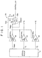
- An optical head or an optical pickup 31 shown in FIG. 1 includes a photodetector (not shown) for detecting the light beam reflected by the magneto-optical disc.
- the output from the photodetector is subjected to an operation process through which an RF signal S ABCD , a tracking error signal TE, and a focusing error signal FE are outputted.
- These signals S ABCD , TE and FE are supplied to a sum signal amplifier 32, a tracking error amplifier 33 and a focusing error amplifier, respectively.
- the RF signal S ABCD amplified by the sum signal amplifier 32 is supplied to an address decoder unit, a data decoder unit (neither shown), and a time constant circuit 35 composed of first and second resistors R1, R2 and a capacitor C.
- the output signal of the time constant circuit 35 is fed back, as an AGC control signal C AGC , to the sum signal amplifier 32, the tracking error amplifier 33 and the focusing error amplifier 34 for controlling the gain of the respective amplifiers 32, 33, 34.
- the gain of each of the amplifiers 32, 33, 34 decreases.
- the gain of each amplifier 32, 33, 34 increases with a decrease in the level of the AGC control signal C AGC .
- the output from each of the amplifiers 32, 33, 34 is controlled at a constant level.
- amplitude levels of the focusing error signal FE and the tracking error signal TE are controlled constantly.
- the time constant circuit 35 includes a switch 36 which is constructed to select a first terminal T1 or a second terminal T2 depending on a switching control signal C SW supplied from a controller (not shown) such as a microcomputer.
- a controller not shown
- the time constant of the time constant circuit 5 is set to a relatively large value due to the combination of the resistors R1, R2 and the capacitor C.
- the time constant of the time constant circuit 5 is set to a relatively small value due to the combination of the resistor R1 and the capacitor C.
- the terminal T1 of the switch 36 is selected to increase the time constant of the AGC control signal C AGC in order to insure a continued recording or reproducing operation without undue fluctuation of the signal level even in the presence of a slight damage on the magneto-optical disc.
- a recording track shown in FIG. 2(a) has a defect Def, such as a flaw, existing at a recording start point or position where the laser power is changed to a high level, as shown in FIG. 2(b).
- Def defect Def
- the detected quantity of the light beam reflecting from the magneto-optical disc is reduced.
- the time constant of the AGC control signal C AGC is set to have a small value under the control of the switching control signal C SW shown in FIG. 2(c). Accordingly, the AGC control signal C AGC instantaneously follows up an increase in the laser power, thereby increasing the gain of the amplifiers 32, 33, 34 abruptly.
- the amplitude level of the tracking error signal TE becomes unstable, as shown in FIG. 2(e), so that the servo operation is performed unstably.
- the same may be said of the focusing error signal FE.
- an operation failure such as a defocusing or a track jump is likely to occur, disabling the recording apparatus from continuing the normal recording operation.
- an object of the present invention to provide a recording apparatus for an optical recording medium which is able to solve the above-mentioned problems.
- a recording apparatus for an optical recording medium having a pregroove and address data.
- the recording apparatus includes a recording head apparatus and a controller.
- the recording head apparatus has an optical head device and records data on the optical recording medium along the pregroove.
- the optical head device radiates a light beam having an intensity which is enough to record the data on the optical recording medium.
- the optical head device includes a photodetector.
- the controller controls the recording head apparatus and receives an output signal supplied from the photodetector.
- the optical head device is controlled to move a recording start point from the previous recording start point by a predetermined value when the controller detects the occurrence of a recording error according to the output signal from the photodetector and restarted to record the data from the moved recording start point on the optical recording medium.
- an appropriate recording operation can be performed even when a defect such as a flaw is present at the recording start point on the optical recording medium. This is because when the recording error appearing at the beginning of a recording operation is judged as caused by the defect, the recording start point is shifted by a predetermined value, or the recording is restarted from a position which is to lapse a predetermined period from the recording start address.
- the optical recording medium used in the illustrated embodiment is a magneto-optical disc.
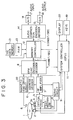
- FIG. 3 shows a block diagram of a main portion of the recording and reproducing apparatus.
- reference numeral 1 designates a magneto-optical disc on which a plurality of pieces of data, such as audio signals, musical information and general information, are already recorded or to be recorded.
- the magneto-optical disc 1 includes a substrate made of a transparent material, a recording layer formed on the substrate, and a protective layer covering the recording layer.
- the magneto-optical disc 1 has a pregroove which is a groove previously formed in order to guide a light beam emitted from an optical head described later. The pregroove wobbles in the radial direction of the magneto-optical disc 1 according to address data.
- Reference numeral 2 denotes a spindle motor provided for rotationally driving the magneto-optical disc 1 at a constant linear velocity (CLV) or a constant angular velocity (CAV).
- the spindle motor 2 has a rotating shaft whose front end is connected to a turntable (not shown) on which the magneto-optical disc 1 is placed.
- the optical head designated by numeral 3 in FIG. 3, is disposed in a position confronting the substrate of the magneto-optical disc 1.
- the optical head 3 irradiates the magneto-optical disc 1 with a light beam having an output power level or intensity which is enough to perform the recording operation.
- the optical head 3 irradiates the magneto-optical disc 1 with a light beam whose output level is lower than as required in the recording mode.
- the light beam irradiated from the optical head 3 is focused on the recording layer of the magneto-optical disc 1.
- the optical head 3 includes an optical system, a light source, such as a laser diode, a polarized beam splitter, and an objective lens 3a, and further has a photodetector having a plurality of light-receiving portions.
- the optical head 1 is provided with an actuator 4, such as an electromagnetic actuator.
- the actuator 4 drives the objective lens 3a in a focusing direction and a tracking direction, respectively, according to a focusing error signal and a tracking error signal both of which will be described later.
- the optical head 3 is moved in the radial direction of the magneto-optical disc 1 by a feed mechanism 5.
- Reference numeral 6 denotes a magnetic head which is disposed in confrontation to the protective layer of the magneto-optical disc 1 and located close to the magneto-optical disc 1 for generating, as an external magnetic field generator, a vertical magnetic field according to the recording data.
- the magnetic head 6 includes an electromagnet which is constituted a magnetic substance and a coil wound around the magnetic substance.
- the magnetic head 6 is attached to the distal end of an arm member (not shown) and disposed in confronted relation to the objective lens 3a of the optical head 3, with the magneto-optical disc 1 interposed between the magnetic head 6 and the objective lens 3a.
- the proximal end of the arm member is connected to the optical head 3 so that when the optical head 3 is displaced in the radial direction of the magneto-optical disc 1 by the feed mechanism 5, the magnetic head 6 is also displaced in the radial direction of the magneto-optical disc 1 together with the optical head 3.
- the respective light receiving portions of the photodetector in the optical head 3 supply output signals to an RF amplifier 7.
- the output signals received from the respective light-receiving portions of the photodetector are used to carry out an arithmetic operation process.
- the RF amplifier 7 generates an RF signal, a focusing error signal, a tracking error signal, a focus monitor signal, etc.
- a low frequency component of the tracking error signal is supplied via a servo circuit, described later, to the feed mechanism 5 so as to move the optical head 3 in the radial direction of the magneto-optical disc 1 in synchronism with the progress of the recording/reproducing operation.
- a first encoder/decoder receives the RF signal supplied from the RF amplifier 7, address data supplied from an address decoder (described later), and recording data supplied from a memory controller (described later).
- the first encoder/decoder 8 conducts an EFM (Eight to Fourteen Modulation) process and a decoding process such as a CIRC (Cross Interleave Reed-Solomon Code) decoding process that are taken in conjunction with the RF signal received from the RF amplifier 7.
- EFM Eight to Fourteen Modulation
- CIRC Cross Interleave Reed-Solomon Code
- Reference numeral 9 denotes a servo circuit to which are supplied error signals including the focusing error signal, the tracking error signal outputted from the RF amplifier 7.
- the servo circuit 9 generates a focus servo signal, a tracking servo signal, and a spindle servo signal according to the error signals supplied thereto.
- the focus servo signal and the tracking servo signal are supplied to the actuator 4 to move the objective lens 3a in the focusing direction and the tracking direction.
- the spindle servo signal is supplied to the spindle motor 2 to take up or cancel rotational deviations of the spindle motor 2.
- the magneto-optical disc 1 is rotated at the CLV or the CAV.
- the address decoder receives a signal such as a push-pull signal which is supplied from the RF amplifier 7 when the wobbling pregroove of the magneto-optical disc 1 is detected.
- the address decoder 10 demodulates the address data according to the push-pull signal as a pregroove detection signal supplied from the RF amplifier 7.
- the demodulated address data is supplied to the first encoder/decoder 8 and also to the system controller (described later) via the first encoder/decoder 8.
- the address decoder 10 also receives the RF signal from the RF amplifier 7. From the RF signal, the address decoder 10 extracts address information recorded as data and supplies the extracted address information to the system controller via the first encoder/decoder 8.
- the system controller denoted by numeral 11 in FIG. 3, comprises a microcomputer, for example.
- the system controller 11 receives the address information or data supplied from the address decoder 10, the focus monitor signal supplied from the RF amplifier 7.
- the system controller 11 is connected with an operator console or input unit 19 and a display unit 20.
- the operator input unit 19 includes a plurality of keys, such as a record key, a reproducing or playback key, a stop key, a search key, all of which are operated by the user. When any one of the keys is operated, a corresponding input signal is supplied to the system controller 11.
- the display unit 20 is used a liquid crystal display, for example, and gives visual representation of data, such as elapsed time or the like time information, title, music number, etc., according to display control signals supplied from the system controller 11.
- the system controller 11 controls the operation of the optical head 3, the RF amplifier 7, the first encoder/decoder 8, the servo circuit 9 and the memory controller (described later).
- a lock detection signal of a PLL (phase-locked loop) circuit which generates a bit clock for a recording or a playback operation, and a monitor signal observing the absence of a frame synchronizing signal of the reproducing data (left and right channels).
- the system controller 11 includes a detecting means or unit which detects a recording error depending on an extraordinary focus monitor signal, an discontinuity in a series of address information, or an incapability in extracting the address information.
- the memory controller designated by numeral 12 shown in FIG. 3, controls write and read operations of a memory 13.
- the memory controller 12 is supplied with reproducing data outputted from the first encoder/decoder 8 at a transfer rate 1.41 Mbit/sec.
- the memory controller 12 first writes the reproducing data to the memory 13.
- the thus stored reproducing data is read out from the memory 13 at a transfer rate 0.3 Mbit/sec and then supplied to a second encoder/decoder (described later) by means of the memory controller 12.
- the memory 13 is used a random access memory (RAM) of a 1 Mbytes capacity.
- the second encoder/decoder 14 is provided for achieving an audio speech compression/expansion process.
- the reproducing data is supplied from the memory 13 to the second encoder/decoder 14 at the transfer rate 0.3 Mbit/sec.
- time-axis components of digital data supplied from an analog-to-digital (A/D) converter (described later) are separated into predetermined frequency components through a MDCT (Modified Discrete Cosine Transform) process and subsequently compressed using an audio masking effect.
- MDCT Modified Discrete Cosine Transform
- the second encoder/decoder 14 also expands the compressed data such as the reproducing data read from the memory 13.
- the digital data expanded by the second encoder/decoder 14 is supplied to a digital-to-analog (D/A) converter 15 where the digital data is converted into an analog signal.
- the thus converted analog audio signal is outputted from an output terminal 16 to an external amplification circuit, for example, as audio signals of left and right channels.
- An analog audio signal inputted from an input terminal 17 is supplied to the A/D converter 18 where the analog signal is converted into a digital audio signal of 16 bits, for example.
- the digital audio signal is then supplied to the second encoder/decoder 14.
- a drive circuit 22, associated with the magnetic head 6, is supplied with encoded recording data from the first encoder/decoder 8.
- the drive circuit 22 drives the magnetic head 6 according to the encoded recording data.
- Numeral 21 designates a memory for storing therein table of contents (TOC) information which is read from the magneto-optical disc 1.
- the memory 21 (hereinafter referred to as "TOC memory”) is used a RAM, for example.
- the TOC information is read from the magneto-optical disc 1 in a manner described below.
- the focus servo system and the tracking servo system of the optical head 3 as well as the servo system of the spindle motor 2 are set up or activated.
- the TOC information is read by the optical head 3 from the magneto-optical disc 1.
- the TOC information is then supplied to the RF amplifier 7, the first encoder/decoder 8, and the memory controller 12 and finally stored in the TOC memory 21.
- the TOC information stored in the TOC memory 21 is used by the system controller 11 for controlling the recording and playback operations effected on the magneto-optical disc 1.
- management data for discriminating a recordable area and a recorded area viz., user TOC information can be recorded.
- the content of the user TOC information is renewed or updated each time a recording operation or an erasing operation is performed.
- the recording and playback operations are achieved according to the updated user TOC information.
- the RF amplifier 7 is provided with an AGC circuit such as shown in FIG. 1, so that the amplitude of the RF signal, focusing error signal and tracking error signal that are supplied from the RF amplifier 7 is controlled at a constant level.
- the AGC circuit executes a time constant controlling operation under the control of the system controller 11 such that the time constant is reduced only when the laser power is increased when the recording operation is started.
- the optical head 3 reads out the data from the magneto-optical disc 1 at a read rate 1.41 Mbit/sec and transfers the reproducing data therefrom to the memory 13 at a transfer rate 1.41 Mbit/sec.
- a recording signal such as an analog audio signal
- the digital audio signal is then supplied to the second encoder/decoder 14 where the digital audio signal is subjected to an audio speech compression encoding process.
- Digital data which has been compressed by the second encoder/decoder 14 is temporarily written by the memory controller 12 to the memory 13 at a transfer rate 0.3 Mbit/sec.
- the digital data thus stored in the memory 13 is read by the memory controller 12 and subsequently supplied to the first encoder/decoder 8 at the transfer rate 1.41 Mbit/sec.
- the digital data is encoded through the CIRC encoding process or the EFM process.
- the recording data outputted from the first encoder/decoder 8 is supplied to the magnetic head drive circuit 22.
- the magnetic head drive circuit 22 supplies a drive signal to the magnetic head 6 according to the encoded recording data.
- a vertical magnetic field is applied to the magneto-optical disc 1 by means of the magnetic head 6.
- the system controller 11 supplies a control signal to the optical head 3 for causing the optical head 3 to emit a light beam with a recording level.
- the magneto-optical disc 1 To read data from the magneto-optical disc 1, the magneto-optical disc 1 is completely loaded on the recording and reproducing apparatus whereupon the TOC information, namely the user TOC information in this case, is readout from the magneto-optical disc 1 and then stored in the TOC memory 21. Based on the TOC information stored in the TOC memory 21, items of information such as total play time, total number of recorded musical compositions, and title of the musical composition are displayed on the display unit 20.
- a key on the operator input unit 19 is operated by the user to input to the system controller 11 a signal representing the selection of music or the playback start, whereupon the system controller 11 sends a control signal to the optical head 3, causing the optical head 3 to irradiate the magneto-optical disc 1 with a light beam having an output power level or intensity which is enough to perform the reproducing or playback operation.
- the light beam is reflected by the magneto-optical disc 1 and then detected by the photodetector incorporated in the optical head 3.
- the photodetector supplies an output signal to the RF amplifier 7. Error signals outputted from the RF amplifier 7 are supplied to the servo circuit 9 to accomplish various servo control operations.
- the RF signal from the RF amplifier 7 is temporarily stored in the memory 13 via the first encoder/decoder 8 and the memory controller 12.
- the reproducing data temporarily stored in the memory 13 is then supplied via the memory controller 12 to the second encoder/decoder 14 where an expanding process is effected on the reproducing data.
- the expanded reproducing data is supplied to the D/A convertor 15 where the digital audio data as the reproducing data is converted to an analog audio signal which is subsequently outputted from the output terminal 16.
- the magneto-optical disc 1 has tracks whose recording unit is set to one cluster.
- the length of one cluster is equal to the length of two to three tracks.
- each cluster is composed of 36 sectors which starts from FC and is ended with 1F. Address information is given to each sector by the pregroove. In the recording operation, address information is written, as data, to each sector.
- the data recording is effected on a cluster shown in FIG. 5(a).
- the recording is executed from the second sector FD of the cluster, and the output power level or the intensity of a light beam emitted from the optical head 3 is kept at the recording level during a period corresponding to the distance between the sector FD and a sector FD of the next cluster, as shown in FIG. 5(b).
- the system controller 11 controls the power level of the light beam such that when a 6.7 msec period running from the arrival of the optical head 3 or the light beam at the sector FD elapses, the laser power, i.e., the intensity of the light beam is shifted up to the recording level.
- the laser power is kept at the recording level until after a 6.7 msec period following the arrival of the optical head 3 or the light beam at a sector FD of the next cluster elapses. During that time, the recording operation is performed. Since each sector requires a 13.3 msec period for scanning, a point of time or instant at which the 6.7 msec period following the arrival of the optical head or the light beam at the sector FD elapses is located at the center of the sector FD.
- an abnormality in terms of an extraordinary focus monitor signal, a discontinuity in the series of extracted addresses caused by the tack jump, or an impossibility in extracting the address is detected by the detecting unit of the system controller 11.
- the system controller 11 judges the detected phenomenon to have been caused by the presence of the defect Def and, based on this judgment, a countermeasure or recovery action is taken by the system controller 11, as described below.
- the recording operation continues successfully without involving any recording error even when a defect Def is actually present, this means that the discontinuity in the extracted addresses does not occur. In this case, no recovery action is taken by the system controller 11.
- the recording start point or position is variable within a range of ⁇ 1.36 msec about the elapsing position of the 6.7 msec period on the sector FD. Accordingly, the recovery action is carried out by changing the recording start position within the range specified above. For instance, when an error is caused due to the laser power control shown in FIG. 5(d), the same cluster is scanned again and, as shown in FIG. 5(e), the laser power is shifted up at a position on the sector FD which is to lapse a period of 5.7 msec, running from the arrival of the optical head 3 or the light beam at the sector FD, elapses.
- the recording start position is changed again such that the laser power is shifted up at a position on the sector FD at which, as shown in FIG. 5(e), a 7.7 msec period running from the detection of the arrival of the light beam at the sector FD elapses. With this position shift, influences effected by the defect Def can be taken up, so that the recording operation continues successfully.
- an error counter E CNT in the system controller 11 is set to "0" (step F101). Then, a recordable are is determined according to the user TOC information and the optical head 3 and the magnetic head 6 are set to a cluster position which is designated as a recording area. (step F102).
- the laser power control shown in FIG. 5(d) is executed.
- the arrival of the light beam at the second sector FD of the next cluster is detected while continuing the recording operation (steps F109 and F110).
- a waiting or standby period of 6.7 msec is set (step F111).
- the output level or intensity of the light beam is lowered to a reproducing or playback level and the recording operation is suspended (step F112).
- the error counter in the system controller 11 resets the count number E CNT to zero (step F113).
- step F114 and F116 the recording operation is terminated.
- step F115 the address of a cluster to which a subsequent recording operation is performed. Then the control returns to the step F102 and the recording operation is effected on the thus set cluster.
- step F110 the control advances from the step F110 to a step F117.
- the system controller 11 recognizes the presence of the defect and starts taking a countermeasure to recover the recording error.
- the laser power is lowered to the reproducing or playback level (step F117), and subsequently the error counter in the system counter 11 adds to the present count number E CNT an increment of 1 (step F118).
- the control returns to the step F102 at which access to the recording start address is performed again until the light beam arrives at the sector FD (step F103).
- the control goes on from the step F119 to a step F120 at which the recording is started after the elapse of a 5.7 msec waiting or standby period. Subsequently, the time constant of the AGC control signal is controlled and the power level of the light beam is shifted up in the same manner as described above (steps F106, F107 and F108).
- the laser power is shifted in the manner shown in FIG. 5(e). In this instance, the recording operation starts from a recording start position which is displaced or shifted from that in the preceding recording operation in which the recording error took place. With the thus displaced recording start position, it is almost possible to cancel out the influence of the defect Def, thereby enabling the recording operation to be achieved successfully.
- step F117 the output level of the light beam is lowered to the reproducing or playback level
- step F118 the count number E CNT of the error counter is increased by one increment
- step F103 the control returns to the step F102 at which access to the recording start position is executed again until the light beam arrives at the sector FD (step F103).
- the control advances from a step F121 to a step F122 at which the recording is started after the elapse of a 7.7 msec waiting or standby period. With the waiting period thus provided, the recording operation is started from a recording start position which is displaced from that in the preceding reading operation.
- the recording error may occur even after the recording start position is changed twice, In that instance, the count number E CNT of the error counter is 3. In the case of the illustrated embodiment, this means that the recording is not possible. Thus, the recording operation is stopped (step F123). However, the recording start position may be changed three times or more.
- the recording start position is shifted in 1 msec increments,
- the increment should be construed as illustrative and not restrictive.
- the recording and reproducing apparatus is used exclusively for a purpose of recording general data other than audio signals, the second encoder/decoder 14 and the memory 13 can are omitted.
- the principle of the present invention is embodied a recording and reproducing apparatus.
- the invention can also be embodied in a recording apparatus which is used exclusively for recording purposes.
- the invention is applicable to a recording apparatus which is used with an erasable optical disc other than the magneto-optical disc.
Landscapes
- Physics & Mathematics (AREA)
- Optics & Photonics (AREA)
- Engineering & Computer Science (AREA)
- Signal Processing (AREA)
- Optical Recording Or Reproduction (AREA)
- Signal Processing For Digital Recording And Reproducing (AREA)
Applications Claiming Priority (2)
| Application Number | Priority Date | Filing Date | Title |
|---|---|---|---|
| JP30783892A JP3225640B2 (ja) | 1992-10-23 | 1992-10-23 | 記録装置 |
| JP307838/92 | 1992-10-23 |
Publications (3)
| Publication Number | Publication Date |
|---|---|
| EP0594132A2 true EP0594132A2 (fr) | 1994-04-27 |
| EP0594132A3 EP0594132A3 (fr) | 1995-03-08 |
| EP0594132B1 EP0594132B1 (fr) | 1998-09-02 |
Family
ID=17973812
Family Applications (1)
| Application Number | Title | Priority Date | Filing Date |
|---|---|---|---|
| EP93116888A Expired - Lifetime EP0594132B1 (fr) | 1992-10-23 | 1993-10-19 | Appareil d'enregistrement pour un support d'enregistrement optique |
Country Status (5)
| Country | Link |
|---|---|
| US (1) | US5559780A (fr) |
| EP (1) | EP0594132B1 (fr) |
| JP (1) | JP3225640B2 (fr) |
| KR (1) | KR100256012B1 (fr) |
| DE (1) | DE69320748T2 (fr) |
Cited By (4)
| Publication number | Priority date | Publication date | Assignee | Title |
|---|---|---|---|---|
| EP0718831A3 (fr) * | 1994-12-20 | 1997-05-21 | Matsushita Electric Industrial Co Ltd | Procédé d'enregistrement et lecture d'un milieu d'enregistrement optique d'information |
| WO1997030439A3 (fr) * | 1996-02-16 | 1997-09-25 | Philips Electronics Nv | Dispositif d'enregistrement d'un support d'information, procede et support d'information a cet effet |
| EP0847046A3 (fr) * | 1994-12-20 | 1998-07-01 | Matsushita Electric Industrial Co., Ltd | Relation variable entre le signal et l'espacement sur un support d'enregistrement optique |
| US6256276B1 (en) * | 1996-06-13 | 2001-07-03 | Sony Corporation | Disk recording and reproducing apparatus and method for use in a rewritable type disk |
Families Citing this family (8)
| Publication number | Priority date | Publication date | Assignee | Title |
|---|---|---|---|---|
| JP3467832B2 (ja) * | 1994-04-20 | 2003-11-17 | ソニー株式会社 | 記録方法及び記録装置 |
| JP3560074B2 (ja) * | 1994-07-29 | 2004-09-02 | ソニー株式会社 | 記録再生装置、及びメモリ制御装置 |
| JP3557721B2 (ja) * | 1995-05-11 | 2004-08-25 | ソニー株式会社 | 記録装置 |
| CN100416661C (zh) * | 1996-02-16 | 2008-09-03 | 皇家菲利浦电子有限公司 | 对信息载体进行记录的装置和方法,和读出这种记录载体的装置 |
| KR100465967B1 (ko) * | 1996-09-02 | 2005-04-13 | 삼성전자주식회사 | 하드디스크드라이브의데이타리드향상방법 |
| JP2001157154A (ja) * | 1999-11-26 | 2001-06-08 | Sony Corp | 記録又は再生装置、及び再生装置 |
| CN100535953C (zh) * | 2006-12-08 | 2009-09-02 | 英业达股份有限公司 | 建立工作感测器数据记录的方法及伺服系统 |
| US10026443B1 (en) * | 2017-05-22 | 2018-07-17 | Seagate Technology Llc | Heat-assisted magnetic recording error-recovery by erasing adjacent tracks using laser |
Family Cites Families (28)
| Publication number | Priority date | Publication date | Assignee | Title |
|---|---|---|---|---|
| US3657707A (en) * | 1969-03-17 | 1972-04-18 | Precision Instr Co | Laser recording system with both surface defect and data error checking |
| US4611318A (en) * | 1973-02-20 | 1986-09-09 | Discovision Associates | Method and apparatus for monitoring the storage of information on a storage medium |
| US4980878A (en) * | 1981-02-02 | 1990-12-25 | Discovision Associates | Method and apparatus for scanning a recording medium for defects |
| JPS5965946A (ja) * | 1982-10-06 | 1984-04-14 | Hitachi Ltd | ビデオデイスクプレ−ヤ |
| US4648085A (en) * | 1983-05-12 | 1987-03-03 | Nec Corporation | Optical information recording and reading apparatus with error correction |
| US4791622A (en) * | 1983-09-19 | 1988-12-13 | Storage Technology Partners 11 | Optical data format employing resynchronizable data sectors |
| JPS6129421A (ja) * | 1984-06-15 | 1986-02-10 | Olympus Optical Co Ltd | 光学式記録媒体の欠陥検出方法 |
| JPS6117274A (ja) * | 1984-07-04 | 1986-01-25 | Nec Corp | 光デイスク制御装置 |
| US4631706A (en) * | 1984-11-19 | 1986-12-23 | International Business Machines Corporation | System for preventing the overwriting of previously optically recorded data and for reading optically recorded data during writing |
| JPS61198430A (ja) * | 1985-02-28 | 1986-09-02 | Canon Inc | 光学式情報記録装置 |
| US4841498A (en) * | 1985-03-11 | 1989-06-20 | Matsushita Electric Industrial Co., Ltd. | Information recording/reproducing apparatus with means for substituting predetermined good sectors for defective ones |
| JPS61208673A (ja) * | 1985-03-12 | 1986-09-17 | Matsushita Electric Ind Co Ltd | 情報記録再生装置 |
| US5247505A (en) * | 1985-04-17 | 1993-09-21 | Canon Kabushiki Kaisha | Information recording method for reciprocally recording and verifying information |
| JPH0756734B2 (ja) * | 1985-05-27 | 1995-06-14 | 松下電器産業株式会社 | 情報記録再生装置 |
| JPS62102482A (ja) * | 1985-10-28 | 1987-05-12 | Matsushita Electric Ind Co Ltd | 情報記録再生装置 |
| DE3704898A1 (de) * | 1986-02-20 | 1987-08-27 | Sharp Kk | Diskettenaufzeichnungs-pruefverfahren |
| US4789974A (en) * | 1986-09-16 | 1988-12-06 | Matsushita Electric Industrial Co., Ltd. | Optical information recording/reproducing apparatus |
| EP0272029B1 (fr) * | 1986-12-19 | 1993-09-15 | Matsushita Electric Industrial Co., Ltd. | Disque optique effaçable et appareil pour enregistrer et reproduire optiquement des informations comprenant un dispositif pour gérer les secteurs défectueux |
| JPS63225925A (ja) * | 1987-03-16 | 1988-09-20 | Olympus Optical Co Ltd | 光カ−ドへのデ−タ記録方法 |
| US5018124A (en) * | 1987-03-31 | 1991-05-21 | Canon Kabushiki Kaisha | Information recording method and apparatus for recording information on track positioned at least two tracks ahead when abnormality of tracking servo is detected |
| US4974221A (en) * | 1987-07-17 | 1990-11-27 | Canon Kabushiki Kaisha | Method and apparatus for reproducing information by varying a sensitivity of a phase-locked loop in accordance with a detection state of a reproduced signal |
| JP2974149B2 (ja) * | 1989-06-23 | 1999-11-08 | 株式会社日立製作所 | 光ピックアップによりデータの記録および再生の少なくとも一方を行う装置 |
| US5142515A (en) * | 1989-11-13 | 1992-08-25 | North American Philips Corporation | Sector slip with address collision recovery for write once recording media |
| JP3065631B2 (ja) * | 1990-02-28 | 2000-07-17 | オリンパス光学工業株式会社 | 光ディスクドライブ装置 |
| JPH0423273A (ja) * | 1990-05-17 | 1992-01-27 | Matsushita Electric Ind Co Ltd | 光ディスク記録再生装置 |
| US5255270A (en) * | 1990-11-07 | 1993-10-19 | Emc Corporation | Method of assuring data write integrity on a data storage device |
| JP3622986B2 (ja) * | 1991-07-16 | 2005-02-23 | ソニー株式会社 | デイスク記録装置 |
| JP3257027B2 (ja) * | 1992-04-17 | 2002-02-18 | ソニー株式会社 | 自己診断情報の記録機構を有する情報記録再生装置 |
-
1992
- 1992-10-23 JP JP30783892A patent/JP3225640B2/ja not_active Expired - Fee Related
-
1993
- 1993-10-19 DE DE69320748T patent/DE69320748T2/de not_active Expired - Fee Related
- 1993-10-19 EP EP93116888A patent/EP0594132B1/fr not_active Expired - Lifetime
- 1993-10-21 KR KR1019930021920A patent/KR100256012B1/ko not_active Expired - Fee Related
-
1995
- 1995-04-19 US US08/426,144 patent/US5559780A/en not_active Expired - Lifetime
Cited By (12)
| Publication number | Priority date | Publication date | Assignee | Title |
|---|---|---|---|---|
| EP0718831A3 (fr) * | 1994-12-20 | 1997-05-21 | Matsushita Electric Industrial Co Ltd | Procédé d'enregistrement et lecture d'un milieu d'enregistrement optique d'information |
| EP0843305A3 (fr) * | 1994-12-20 | 1998-07-01 | Matsushita Electric Industrial Co., Ltd | Procédé d'enregistrement optique à variation d'intensité lumineuse |
| EP0847046A3 (fr) * | 1994-12-20 | 1998-07-01 | Matsushita Electric Industrial Co., Ltd | Relation variable entre le signal et l'espacement sur un support d'enregistrement optique |
| US6031814A (en) * | 1994-12-20 | 2000-02-29 | Matsushita Electric Industrial Co., Ltd. | Optical disk with stop-pulse generating means in a guide groove |
| US6487151B1 (en) | 1994-12-20 | 2002-11-26 | Matsushita Electric Industrial Co. Ltd. | Optical information recording and reproducing system with overwrite capability and recording medium for use therewith |
| US6683739B2 (en) | 1994-12-20 | 2004-01-27 | Matsushita Electric Industrial Co., Ltd. | Optical information recording and reproducing system with overwrite capability and recording medium for use therewith |
| US6697313B2 (en) | 1994-12-20 | 2004-02-24 | Matsushita Electric Industrial Co., Ltd. | Optical information recording and reproducing system with overwrite capability and recording medium for use therewith |
| US6707776B2 (en) | 1994-12-20 | 2004-03-16 | Matsushita Electric Industrial Co., Ltd. | Recording and reproducing method of optical information recording medium |
| WO1997030439A3 (fr) * | 1996-02-16 | 1997-09-25 | Philips Electronics Nv | Dispositif d'enregistrement d'un support d'information, procede et support d'information a cet effet |
| US6115340A (en) * | 1996-02-16 | 2000-09-05 | U.S. Philips Corporation | Modifying the recording process to extend the life of a rewritable information carrier |
| KR100487680B1 (ko) * | 1996-02-16 | 2005-08-29 | 코닌클리케 필립스 일렉트로닉스 엔.브이. | 정보캐리어기록장치및방법과,정보캐리어판독장치와,그프로그래밍장치와,그정보캐리어 |
| US6256276B1 (en) * | 1996-06-13 | 2001-07-03 | Sony Corporation | Disk recording and reproducing apparatus and method for use in a rewritable type disk |
Also Published As
| Publication number | Publication date |
|---|---|
| JPH06139573A (ja) | 1994-05-20 |
| US5559780A (en) | 1996-09-24 |
| EP0594132A3 (fr) | 1995-03-08 |
| KR100256012B1 (ko) | 2000-05-01 |
| DE69320748T2 (de) | 1999-02-04 |
| EP0594132B1 (fr) | 1998-09-02 |
| KR940009989A (ko) | 1994-05-24 |
| DE69320748D1 (de) | 1998-10-08 |
| JP3225640B2 (ja) | 2001-11-05 |
Similar Documents
| Publication | Publication Date | Title |
|---|---|---|
| US5740143A (en) | Disc reproducing apparatus | |
| KR930007686B1 (ko) | 기록 재생장치 | |
| KR100266332B1 (ko) | 광 디스크 기록 장치 | |
| US5487047A (en) | Magnetooptical recording apparatus for recording information in a lead-in region of a recording medium | |
| EP0875894B1 (fr) | Procédé et dispositif de reproduction de support d'enregistrement | |
| US5559780A (en) | Recording apparatus for an optical recording medium | |
| JPH05314655A (ja) | 音響再生装置 | |
| EP0543295A2 (fr) | Tourne-disque optique | |
| JP3192685B2 (ja) | 光ディスク装置 | |
| JP3872619B2 (ja) | バイアス電圧制御装置並びに情報再生装置及び情報記録装置 | |
| JPH05290383A (ja) | 光ディスク | |
| JP3728390B2 (ja) | フォーカスサーボ制御装置並びに情報再生装置及び情報記録装置 | |
| US5740137A (en) | Servo control method for an opto-magnetic disc | |
| JP3303444B2 (ja) | 記録又は再生装置 | |
| JPH06215483A (ja) | 記録装置 | |
| JPH05234095A (ja) | 光ディスクプレーヤ | |
| KR100294615B1 (ko) | 광디스크시스템의코드정보를이용한재생방법 | |
| JP3453774B2 (ja) | 記録装置及び記録方法 | |
| JPH0877577A (ja) | 記録又は再生装置 | |
| JPH06325396A (ja) | 再生装置 | |
| JP3518744B2 (ja) | 再生装置および再生方法 | |
| JPH05166198A (ja) | 利得制御装置 | |
| JP2981031B2 (ja) | 追記型光ディスクの再生方法及び光ディスク再生装置 | |
| JPH0765507A (ja) | ディスク状記録媒体の記録及び/又は再生装置 | |
| JPH09312025A (ja) | 記録又は再生装置 |
Legal Events
| Date | Code | Title | Description |
|---|---|---|---|
| PUAI | Public reference made under article 153(3) epc to a published international application that has entered the european phase |
Free format text: ORIGINAL CODE: 0009012 |
|
| AK | Designated contracting states |
Kind code of ref document: A2 Designated state(s): DE FR GB |
|
| PUAL | Search report despatched |
Free format text: ORIGINAL CODE: 0009013 |
|
| AK | Designated contracting states |
Kind code of ref document: A3 Designated state(s): DE FR GB |
|
| 17P | Request for examination filed |
Effective date: 19950829 |
|
| 17Q | First examination report despatched |
Effective date: 19970127 |
|
| GRAG | Despatch of communication of intention to grant |
Free format text: ORIGINAL CODE: EPIDOS AGRA |
|
| GRAG | Despatch of communication of intention to grant |
Free format text: ORIGINAL CODE: EPIDOS AGRA |
|
| GRAH | Despatch of communication of intention to grant a patent |
Free format text: ORIGINAL CODE: EPIDOS IGRA |
|
| GRAH | Despatch of communication of intention to grant a patent |
Free format text: ORIGINAL CODE: EPIDOS IGRA |
|
| GRAA | (expected) grant |
Free format text: ORIGINAL CODE: 0009210 |
|
| AK | Designated contracting states |
Kind code of ref document: B1 Designated state(s): DE FR GB |
|
| REF | Corresponds to: |
Ref document number: 69320748 Country of ref document: DE Date of ref document: 19981008 |
|
| ET | Fr: translation filed | ||
| PLBE | No opposition filed within time limit |
Free format text: ORIGINAL CODE: 0009261 |
|
| STAA | Information on the status of an ep patent application or granted ep patent |
Free format text: STATUS: NO OPPOSITION FILED WITHIN TIME LIMIT |
|
| 26N | No opposition filed | ||
| REG | Reference to a national code |
Ref country code: GB Ref legal event code: IF02 |
|
| PGFP | Annual fee paid to national office [announced via postgrant information from national office to epo] |
Ref country code: DE Payment date: 20081016 Year of fee payment: 16 |
|
| PGFP | Annual fee paid to national office [announced via postgrant information from national office to epo] |
Ref country code: FR Payment date: 20081014 Year of fee payment: 16 |
|
| PGFP | Annual fee paid to national office [announced via postgrant information from national office to epo] |
Ref country code: GB Payment date: 20081015 Year of fee payment: 16 |
|
| REG | Reference to a national code |
Ref country code: FR Ref legal event code: ST Effective date: 20100630 |
|
| PG25 | Lapsed in a contracting state [announced via postgrant information from national office to epo] |
Ref country code: FR Free format text: LAPSE BECAUSE OF NON-PAYMENT OF DUE FEES Effective date: 20091102 Ref country code: DE Free format text: LAPSE BECAUSE OF NON-PAYMENT OF DUE FEES Effective date: 20100501 |
|
| PG25 | Lapsed in a contracting state [announced via postgrant information from national office to epo] |
Ref country code: GB Free format text: LAPSE BECAUSE OF NON-PAYMENT OF DUE FEES Effective date: 20091019 |