EP0594315B1 - Trennung von Teilchen und Trockner - Google Patents
Trennung von Teilchen und Trockner Download PDFInfo
- Publication number
- EP0594315B1 EP0594315B1 EP93307795A EP93307795A EP0594315B1 EP 0594315 B1 EP0594315 B1 EP 0594315B1 EP 93307795 A EP93307795 A EP 93307795A EP 93307795 A EP93307795 A EP 93307795A EP 0594315 B1 EP0594315 B1 EP 0594315B1
- Authority
- EP
- European Patent Office
- Prior art keywords
- drum
- solids
- plough
- liquid
- side wall
- Prior art date
- Legal status (The legal status is an assumption and is not a legal conclusion. Google has not performed a legal analysis and makes no representation as to the accuracy of the status listed.)
- Expired - Lifetime
Links
Images


Classifications
-
- B—PERFORMING OPERATIONS; TRANSPORTING
- B04—CENTRIFUGAL APPARATUS OR MACHINES FOR CARRYING-OUT PHYSICAL OR CHEMICAL PROCESSES
- B04B—CENTRIFUGES
- B04B11/00—Feeding, charging, or discharging bowls
- B04B11/08—Skimmers or scrapers for discharging ; Regulating thereof
-
- B—PERFORMING OPERATIONS; TRANSPORTING
- B01—PHYSICAL OR CHEMICAL PROCESSES OR APPARATUS IN GENERAL
- B01D—SEPARATION
- B01D33/00—Filters with filtering elements which move during the filtering operation
- B01D33/06—Filters with filtering elements which move during the filtering operation with rotary cylindrical filtering surfaces, e.g. hollow drums
- B01D33/11—Filters with filtering elements which move during the filtering operation with rotary cylindrical filtering surfaces, e.g. hollow drums arranged for outward flow filtration
-
- B—PERFORMING OPERATIONS; TRANSPORTING
- B01—PHYSICAL OR CHEMICAL PROCESSES OR APPARATUS IN GENERAL
- B01D—SEPARATION
- B01D33/00—Filters with filtering elements which move during the filtering operation
- B01D33/44—Regenerating the filter material in the filter
- B01D33/46—Regenerating the filter material in the filter by scrapers, brushes nozzles or the like acting on the cake-side of the filtering element
- B01D33/466—Regenerating the filter material in the filter by scrapers, brushes nozzles or the like acting on the cake-side of the filtering element scrapers
-
- B—PERFORMING OPERATIONS; TRANSPORTING
- B01—PHYSICAL OR CHEMICAL PROCESSES OR APPARATUS IN GENERAL
- B01D—SEPARATION
- B01D33/00—Filters with filtering elements which move during the filtering operation
- B01D33/58—Handling the filter cake in the filter for purposes other than for regenerating the filter cake remaining on the filtering element
- B01D33/60—Handling the filter cake in the filter for purposes other than for regenerating the filter cake remaining on the filtering element for washing
-
- B—PERFORMING OPERATIONS; TRANSPORTING
- B01—PHYSICAL OR CHEMICAL PROCESSES OR APPARATUS IN GENERAL
- B01D—SEPARATION
- B01D33/00—Filters with filtering elements which move during the filtering operation
- B01D33/58—Handling the filter cake in the filter for purposes other than for regenerating the filter cake remaining on the filtering element
- B01D33/62—Handling the filter cake in the filter for purposes other than for regenerating the filter cake remaining on the filtering element for drying
- B01D33/66—Handling the filter cake in the filter for purposes other than for regenerating the filter cake remaining on the filtering element for drying by gases or by heating
- B01D33/663—Handling the filter cake in the filter for purposes other than for regenerating the filter cake remaining on the filtering element for drying by gases or by heating by direct contact with a fluid
-
- B—PERFORMING OPERATIONS; TRANSPORTING
- B01—PHYSICAL OR CHEMICAL PROCESSES OR APPARATUS IN GENERAL
- B01D—SEPARATION
- B01D33/00—Filters with filtering elements which move during the filtering operation
- B01D33/58—Handling the filter cake in the filter for purposes other than for regenerating the filter cake remaining on the filtering element
- B01D33/62—Handling the filter cake in the filter for purposes other than for regenerating the filter cake remaining on the filtering element for drying
- B01D33/66—Handling the filter cake in the filter for purposes other than for regenerating the filter cake remaining on the filtering element for drying by gases or by heating
- B01D33/666—Handling the filter cake in the filter for purposes other than for regenerating the filter cake remaining on the filtering element for drying by gases or by heating by indirect heat-exchange
-
- B—PERFORMING OPERATIONS; TRANSPORTING
- B01—PHYSICAL OR CHEMICAL PROCESSES OR APPARATUS IN GENERAL
- B01D—SEPARATION
- B01D33/00—Filters with filtering elements which move during the filtering operation
- B01D33/70—Filters with filtering elements which move during the filtering operation having feed or discharge devices
- B01D33/76—Filters with filtering elements which move during the filtering operation having feed or discharge devices for discharging the filter cake, e.g. chutes
-
- B—PERFORMING OPERATIONS; TRANSPORTING
- B04—CENTRIFUGAL APPARATUS OR MACHINES FOR CARRYING-OUT PHYSICAL OR CHEMICAL PROCESSES
- B04B—CENTRIFUGES
- B04B15/00—Other accessories for centrifuges
- B04B15/02—Other accessories for centrifuges for cooling, heating, or heat insulating
-
- B—PERFORMING OPERATIONS; TRANSPORTING
- B04—CENTRIFUGAL APPARATUS OR MACHINES FOR CARRYING-OUT PHYSICAL OR CHEMICAL PROCESSES
- B04B—CENTRIFUGES
- B04B15/00—Other accessories for centrifuges
- B04B15/12—Other accessories for centrifuges for drying or washing the separated solid particles
-
- F—MECHANICAL ENGINEERING; LIGHTING; HEATING; WEAPONS; BLASTING
- F26—DRYING
- F26B—DRYING SOLID MATERIALS OR OBJECTS BY REMOVING LIQUID THEREFROM
- F26B7/00—Drying solid materials or objects by processes using a combination of processes not covered by a single one of groups F26B3/00 and F26B5/00
-
- B—PERFORMING OPERATIONS; TRANSPORTING
- B01—PHYSICAL OR CHEMICAL PROCESSES OR APPARATUS IN GENERAL
- B01D—SEPARATION
- B01D2201/00—Details relating to filtering apparatus
- B01D2201/28—Position of the filtering element
- B01D2201/287—Filtering elements with a vertical or inclined rotation or symmetry axis
Definitions
- the present invention relates to apparatus for the separation and drying of particulate particles from a slurry.
- the separation of fine particulate solids from liquids, to produce totally dry solids usually requires two stages of separation.
- the first stage removes the bulk of the liquid by mechanical separating methods using one of several state-of-the-art separators. When this has removed as much liquid as practical, the solids plus the remaining liquid are removed from the first separator and transferred to a second vessel. Heat is applied at this second stage to the partially dried solids at the pressure needed for the process to evaporate the remaining liquid.
- a wide variety of combinations of equipment exist to produce dry or nearly dry solids by this means they are all subjected to limitations, which include the following:-
- a sludge recovery apparatus having a cone-shaped centrifugal separator comprising a hollow, open-bottom, downwardly converging, cone-shaped centrifugal separator member in which a cone-shaped spiral scraper is rotatable, in sliding contact with the inner wall of the separator member, at a differential speed thereto.
- the differential speed between the separator member and scraper is effective to achieve scraping of centrifugally deposited sludge from the inner wall of the separator member and ejection of the sludge out of the open bottom thereof.
- a sludge drying table Disposed separately from the separator member and beneath the open bottom of the separator member is a sludge drying table which is rotated by an electric motor sludge exuded from the separator member onto the top of the table is dried by heating elements disposed above the top of the table to one side of the separator member such apparatus therefore still has the disadvantages of the prior art discussed hereinbefore.
- an apparatus for performing particle separation, drying, and one or more other process functions comprising:-
- the stripping mechanism comprises a plough device which is adapted to be rotated within the drum about an axis parallel to the rotational axis of the drum whereby to enter solids which have been built up in said cylindrical form and also to be displaced longitudinally of its own rotational axis whereby to be advanced along the length of said cylindrical format.
- the plough device is also displaceable laterally to enable its depth of insertion into the solids to be controlled.
- the plough device also carries mixing elements which, when the plough device has been displaced longitudinally to approximately its fullest extent, are adapted to enter solids, which have collected on the drum bottom as a result of stripping by the plough, for stirring such solids so as to ensure maximum contact with the heated parts of the drum.
- the heating means can be adapted to heat the bottom part of the drum either using a hot liquid, hot gas, steam or by electrical heating wires or by the use of electrically induced eddy currents.
- the heating means can also be adapted to heat the plough/mixer elements and/or supply hot air/gas to the solids via the plough/mixer elements.
- the lower end of the drum is of conoidal shape, this lower part of the drum being free of perforations.
- the bottom part of the drum can include a selectably displaceable cover which can be moved between a first, lower position, in which it covers one or a plurality of discharge holes in the drum, and a second, raised position in which it opens said one or plurality of holes to enable solids to be discharged therethrough.
- An apparatus constructed in accordance with the present invention thus uses centrifugal force to reduce liquid and energy usage to a minimum and enables both separating and evaporating stages to be achieved in one enclosure (the centrifugal drum), thereby avoiding any intermediate handling of or exposure of the solids and liquids. Additional operations of solids washing, reslurrying, under vacuum, pressure and/or inert gas blanketting conditions and other reactions are also possible in the same enclosure without intermediate exposure of the solids and liquids.
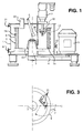
- the apparatus of Fig. 1 includes an enclosure 1 containing a partly perforated drum 2 mounted on a spindle and bearing housing assembly 3 and driven by pulleys, and belts 4 and a variable speed motor 5 (or by other known means).
- a slurry containing the particulate solids to be dried flows through a feed pipe 6 into the drum 2 which is rotated (typically 150-750 rpm) to accelerate the slurry, causing it to flow to a near cylindrical form (as shown at 7A) against the inner surface of the drum wall 2.
- the small perforations 8 in the drum wall, or in a screen 27 (see Fig. 4) fitted inside the drum retain the solids but allow liquid to flow into the enclosure 1 and thence out of a liquid outlet 9.
- the rotational speed of the drum and contents is then raised to a maximum (typically 750-2000 rpm) by the drive motor 5 to apply high centrifugal forces to extract the maximum amount of liquid from the solids.
- a maximum typically 750-2000 rpm
- the drum speed is reduced to a low value (typically 15-40 rpm) and a stripping mechanism in the form of a plough 10, having mixing blades 20, is operated by a plough mechanism 11.
- the operation of the plough 10 is such that it rotates and traverses from the position shown in Fig. 1 along the path 12 shown in dotted line to engage and dislodge the partly dried solids from the inner wall of the drum 2 and to direct them downwardly onto the annular bottom plate 13 of the drum 2 to complete a first drying stage.
- the reversing rotation of the drum and the plough and mixing blades movements are coordinated such as to stir the bed of solids in the drum to expose all solids repeatedly into contact with the heated parts and thus evaporate the liquid residue rapidly.
- the evaporated liquid is withdrawn as a vapour by an air or a gas flow entering the enclosure by an inlet 21 and leaving by an outlet 22.
- the fully dried solids are conveyed from the drum either pneumatically by suction or using other known means, such as a mechanical conveyor.
- a suction pipe 23 positioned as shown in full line in Fig. 1 during both drying stages is mounted on the enclosure 1 with the open, lower end of the pipe inside the drum 2.
- the other upper end of the pipe is connected to a suction fan, vacuum pump or equivalent device (not shown).
- the suction pipe 23 is lowered to the surface of the solids, as shown by dotted line 24 in Fig.
- the drive motor rotates the drum slowly (typically 5-50 rpm), the plough and mixer blades are moved to deflect the solids to a circular path under the suction pipe and the suction fan or vacuum pump runs to extract the solids from the drum, with further downward movement of the suction pipe 23 as the solids are removed to complete the solids removal from the drum bottom plate 13.
- a column, cyclone or other known equipment between the suction device and the enclosure 1 then separates the dried solids from the air/gas stream. After removal of the solids the suction pipe is withdrawn to its original (solid line) position.
- Fig. 4 is a partial view showing a preferred construction for the drum 2.
- An upper cylindrical part 25 of the perforated drum wall is joined to the bottom drum plate 13 by an unperforated conoidal shaped section 26 of vertical dimension X (the vertical distance between the upper face of the bottom of the drum 13 and the lowest perforation opening), X being greater than the depth Y of the partly dried solids (7B) in the second drying stage.
- the conoidal and cylindrical sections are lined with a finely perforated or woven screen 27 to hold back the solids, the screen being spaced from the inner walls of the drum by an open woven gauze 28 or similar material to allow the easy passage of the liquid between this perforated screen 27 and the inner surface of the cylindrical/conoidal bowl 25,26.
- the supply of slurry to be processed takes up the near cylindrical form (7A) with the drum rotating and applying a force many times that of gravity to the drum contents. Under these conditions the liquid in the conoidal section 26 flows through the perforations in the screen 27, through the space provided by the woven gauze 28 and, under the large applied centrifugal force, leaves the drum through the lower perforations 8 in the cylindrical section 25 of the bowl.
- the suction pipe 23, the plough 10 and plough mechanism 11 are combined into one assembly to produce a simpler design.
- a spindle 30 supporting the plough 10 and mixer blades 20 is hollow so as to act also as the suction pipe , the vertical movement during suction being provided by the plough operating mechanism 11.
- the upper end of the hollow spindle 30 is connected by a flexible hose 31, or equivalent, and a valve 32 to the suction fan or vacuum pump and solids removal system (not shown).
- the plough 10 and mixer blades 20 are also hollow, preferably constructed in hollow section materials as shown in Fig. 6, to provide a series of openings 33 in the plough and mixer blades.
- the plough Upon completion of the second or last drying phase, the plough is traversed until the openings 33 are at or below the surface of the dried solids (7B), the valve 32 is opened and suction is applied to extract the solids as described above but through the openings 33. During suction, the drum is rotated slowly and the plough is oscillated and advanced towards the drum bottom plate 13 until all the solids have been removed.
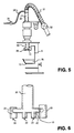
- the hollow spindle 30 can be connected by a second flexible hose 34 and valve 35 to a source of hot air or gas as shown in Fig. 5.
- valve 32 is closed, valve 35 is opened and hot air or gas is arranged to flow through the hollow spindle and the plough openings 33.
- the plough is positioned near or under the surface of the solids (7B) and is oscillated, whilst the drum 8 is rotated slowly to expose all solids to the flow of hot air or gas for rapid stage two drying.
- Figs. 7A and 7B An alternative means of discharging the dried solids that is preferred when processing bulk chemical products is shown in Figs. 7A and 7B.
- the drum bottom 13 is annular in shape and is connected to the drive spindle 36 by a drive plate 37, the drive plate 37 having one or more openings 38 cut there-in for the discharge of dried solids.
- the drive spindle 36 transmits the power of the drive motor 5 to rotate the drum, the spindle 36 being hollow and containing coaxially an actuating spindle 39.
- a conically shaped cover having a flange 40 is attached to the top of the actuating spindle 39, the actuating spindle being capable of being raised and lowered by one of a known means (such as pneumatic or hydraulic cylinder 41, mechanical screw and clutch, linear actuator, etc.).
- a known means such as pneumatic or hydraulic cylinder 41, mechanical screw and clutch, linear actuator, etc.
- the actuating spindle 39 is at or near its lowest position, as shown in Fig. 7A, the outer periphery of the flange 40 seats into the centre of the drum bottom 13 and is sealed there-to by a rubber ring 42, or a known equivalent, to completely cover and seal the opening(s) 38.
- the conical shaped cover having the flange 40 is raised to expose the opening(s) 38 and allow the discharge of dried solids in to the stationary space 43 below the drum.
- First and second stage drying, reslurry washing, reaction and other process stages are all carried out with the opening(s) 38 sealed by the flange 40 as described above, the process stages using centrifugal force, heat, gas flow, vacuum and/or inert gas conditions as required.
- the dried and processed solids are then discharged by raising the flange 40 to expose the openings 38.
- a more complex plough-mixer blade assembly 10,20 is required to perform four functions:-
- Fig. 8 shows, in plan view on section XX of Fig. 7 and to a larger scale, one arrangement of a plough/mixer blade assembly that meets the latter requirements, this being one of a variety of designs required for centri-dryers of varying dimensions.
- the plough-mixer blade assembly 10,20 is angled in plan and profiled to the angles of the drum 25 and conoidal section 26 sweeps over an arc ⁇ 1 for function C to discharge the centrifuged solids from the drum and over an arc ⁇ 2 for function B to sweep the drum bottom and flange.
- the angled shape of the plough-mixer blade assembly allows the plough to pass the outer edge of the flange 40 and take up a position below the flange. Suitable angular and transitional controls and interlocks in the plough operating mechanism 11 ensure the required movements of the plough-mixer blade assembly.
- any solids supported by the horizontal surface of the raised flange 40 are removed by intermittently raising the speed of the drum to dislodge them.
- one or more blades 46 on the underside of the slowly rotating drive plate 37 displace and eject the solids through second openings 47 to a receiving vessel (not shown) for the processed solids.
- the flange 40 is raised for the discharging of solids.
- the flange 40 can be positioned under the drum drive plate 37 so that the flange is lowered for discharging solids and raised to seal the drum.
- the centrifugal dryer reduces uneconomic evaporative drying to a minimum and allows a variety of processes, including drying, washing, reslurry washing, reaction and crystal growth under a sealed vacuum, pressure and/or inert gas environment, encased in a single enclosure that remains unopened during all processes. Completing several processes in one enclosure provides the advantages that it:-
Landscapes
- Chemical & Material Sciences (AREA)
- Chemical Kinetics & Catalysis (AREA)
- Engineering & Computer Science (AREA)
- Mechanical Engineering (AREA)
- General Engineering & Computer Science (AREA)
- Drying Of Solid Materials (AREA)
- Centrifugal Separators (AREA)
- Physical Or Chemical Processes And Apparatus (AREA)
Claims (9)
- Vorrichtung zur Abscheidung von Partikeln aus einem Flüssigkeits-/Feststoff-Schlamm, umfassend:(a) eine teilweise perforierte Zentrifugentrommel (2), die um eine senkrechte Achse in einer Mehrzahl von wählbaren Geschwindigkeiten drehbar ist, einschließlich einer hohen Geschwindigkeit, bei der die Zentrifugalwirkungen auf Material in der Trommel im wesentlichen derart sind, daß sich teilgetrocknete Feststoffe in einer im wesentlichen zylindrischen Form an der Seitenwand der Trommel sammeln, und einer niedrigen Geschwindigkeit, bei der die Zentrifugalwirkungen auf Material in der Trommel vernachlässigbar sind;(b) einen Ablösemechanismus (10), der innerhalb der Trommel (2) verschiebbar ist, wenn die Trommel (2) mit der genannten geringen Geschwindigkeit gedreht wird, um Feststoffe, die sich während der Rotation mit der genannten hohen Geschwindigkeit an der Seitenwand der Trommel in der genannten, im wesentlichen zylindrischen Form angesammelt haben, zu lösen; und(c) ein Mittel (15) zum Erhitzen wenigstens eines Bodenteils der Trommel, an dem sich teilgetrocknete Feststoffe sammeln, wenn sie von dem Ablösemechanismus (10) von der Seitenwand der Trommel gelöst wurden, so daß die genannten Feststoffe selbst erhitzt oder auf andere Weise bearbeitet werden, damit eventuell vorhandene Restflüssigkeit davon verdampft.
- Vorrichtung nach Anspruch 1, wobei der Ablösemechanismus eine Pflügvorrichtung (10) umfaßt, die innerhalb der Trommel (2) um eine Achse parallel zur Rotationsachse der Trommel gedreht werden kann, so daß sie in Feststoffe eindringt, die sich in der genannten zylindrischen Form angesammelt haben, und die auch in Längsrichtung von ihrer eigenen Rotationsachse verschoben werden kann, so daß sie über die Länge des genannten zylindrischen Formats vorgerückt werden kann.
- Vorrichtung nach Anspruch 2, wobei die Pflügvorrichtung (10) auch lateral verschieblich ist, so daß ihre Eindringtiefe in die Feststoffe geregelt werden kann.
- Vorrichtung nach Anspruch 2 oder 3, wobei die Pflügvorrichtung (10) auch Mixerelemente (20) trägt, die, wenn die Pflügvorrichtung in Längsrichtung etwa über ihre volle Reichweite verschoben wurde, in Feststoffe eindringen können, die sich auf Grund des Ablösens durch den Pflug am Trommelboden gesammelt haben, um solche Feststoffe zu rühren, so daß beim Waschen der Feststoffe eine beträchtliche Rührwirkung erzielt und beim Trocknen der Feststoffe ein maximaler Kontakt mit den erhitzten Teilen der Trommel gewährleistet wird.
- Vorrichtung nach Anspruch 1, 2, 3 oder 4, wobei das Heizmittel den Bodenteil der Trommel entweder mit einer heißen Flüssigkeit, einem heißen Gas, mit Dampf oder mit elektrischen Heizdrähten oder mit Hilfe von elektrisch induzierten Wirbelströmen aufheizen kann.
- Vorrichtung nach Anspruch 5, wobei das Heizmittel auch die Pflug/Mixer-Elemente erhitzen und/oder den Feststoffen über die Pflug/Mixerelemente Heißluft/-gas zuführen kann.
- Vorrichtung nach einem der Ansprüche 1 bis 6, wobei ein unterer Endabschnitt (26) der Trommel (2) konoidal geformt und dieser untere Teil der Trommel perforationsfrei ist.
- Vorrichtung nach einem der Ansprüche 1 bis 7, wobei ein unterer Teil der Trommel eine selektiv verschiebbare Abdeckung (40) aufweist, die zwischen einer ersten Position, in der sie ein oder eine Mehrzahl von Ablauflöchern (38) in der Trommel abdeckt, und einer zweiten Position bewegt werden kann, in der sie das genannte eine oder die Mehrzahl von Löchern freigibt, so daß Feststoffe dadurch auslaufen können.
- Vorrichtung nach einem der Ansprüche 1 bis 8, umfassend ein Mittel (6) zum Zuführen von Waschflüssigkeit zu der Trommel, wenn sich diese mit niedriger Geschwindigkeit dreht, um die gelösten Feststoffe zu waschen, und ein Mittel zum Beschleunigen der Trommel auf die hohe Geschwindigkeit, um den Großteil der Waschflüssigkeit durch Zentrifugalkraft zu entfernen und die Feststoffe in die im wesentlichen zylindrische Form an der Seitenwand der Trommel zurückzubringen.
Applications Claiming Priority (2)
| Application Number | Priority Date | Filing Date | Title |
|---|---|---|---|
| GB9221956 | 1992-10-20 | ||
| GB929221956A GB9221956D0 (en) | 1992-10-20 | 1992-10-20 | Particle separation and drying apparatus |
Publications (2)
| Publication Number | Publication Date |
|---|---|
| EP0594315A1 EP0594315A1 (de) | 1994-04-27 |
| EP0594315B1 true EP0594315B1 (de) | 1997-06-11 |
Family
ID=10723707
Family Applications (1)
| Application Number | Title | Priority Date | Filing Date |
|---|---|---|---|
| EP93307795A Expired - Lifetime EP0594315B1 (de) | 1992-10-20 | 1993-09-30 | Trennung von Teilchen und Trockner |
Country Status (5)
| Country | Link |
|---|---|
| US (1) | US5460717A (de) |
| EP (1) | EP0594315B1 (de) |
| JP (1) | JPH06281325A (de) |
| DE (1) | DE69311495T2 (de) |
| GB (1) | GB9221956D0 (de) |
Families Citing this family (29)
| Publication number | Priority date | Publication date | Assignee | Title |
|---|---|---|---|---|
| NL9201731A (nl) * | 1992-10-07 | 1994-05-02 | Rowe Parsons Int Inc | Filterinrichting. |
| JP3313286B2 (ja) * | 1996-01-17 | 2002-08-12 | 株式会社松本機械製作所 | 遠心ろ過方法及び装置 |
| US5743840A (en) * | 1996-06-24 | 1998-04-28 | Carr Separations, Inc. | Centrifuge with a heating jacket for drying collected solids |
| US6159360A (en) * | 1996-11-22 | 2000-12-12 | Heinkel Industriezentrifugen Gmbh & Co. | Invertible filter centrifuge including a solids drier |
| US5954071A (en) * | 1997-01-15 | 1999-09-21 | Magliocca; Charles Thomas | Parts washing apparatus with centrifugal filter |
| DE19817275C1 (de) * | 1998-04-18 | 1999-07-15 | Braunschweigische Masch Bau | Verfahren und Vorrichtung zum Decken des Zuckers |
| DE19819065C1 (de) * | 1998-04-29 | 1999-10-14 | Braunschweigische Masch Bau | Verfahren und Vorrichtung zum Ausräumen des Produktes aus einer Zentrifugentrommel |
| DE10043077B4 (de) * | 1999-10-04 | 2011-03-17 | Thomas Spyra | Schubzentrifuge |
| EP1220718B1 (de) * | 1999-10-12 | 2007-01-10 | Pneumatic Scale Corporation | Regelung der trennleistung in einer zentrifuge |
| US6632166B2 (en) * | 2000-08-04 | 2003-10-14 | Robert B. Carr | Centrifuge having axially movable scraping assembly for automatic removal of solids |
| CN1139420C (zh) * | 2001-01-15 | 2004-02-25 | 牛子久 | 旋转式钻井液过滤设备及使用该设备过滤钻井液的方法 |
| US6430842B1 (en) | 2001-05-09 | 2002-08-13 | Carter Day International, Inc. | Assembly for supporting a rotating structure |
| US6591515B2 (en) | 2001-09-10 | 2003-07-15 | Kemet Electronics Corporation | Mobile incline kinetic evaporator |
| US20030233765A1 (en) * | 2002-04-30 | 2003-12-25 | Alan Heinzen | Centrifugal dryer and method |
| US7028415B2 (en) * | 2002-04-30 | 2006-04-18 | Alan Heinzen | Canted manually loaded produce dryer |
| DE10235067A1 (de) * | 2002-07-31 | 2004-02-12 | Knoll Maschinenbau Gmbh | Vorrichtung zur Abtrennung einer Flüssigkeit aus einem Flüssigkeits-Feststoff-Gemisch |
| JP4755815B2 (ja) * | 2004-09-06 | 2011-08-24 | 株式会社神鋼環境ソリューション | 濾過乾燥機と、その濾過乾燥機を用いた濾過乾燥方法 |
| JP4755852B2 (ja) * | 2005-05-31 | 2011-08-24 | 株式会社神鋼環境ソリューション | 濾過乾燥機 |
| US7775962B2 (en) * | 2005-08-10 | 2010-08-17 | The Regents Of The University Of California | Centrifuge with polymerizing energy source |
| US8502075B2 (en) * | 2008-03-10 | 2013-08-06 | Quick Connectors, Inc | Heater cable to pump cable connector and method of installation |
| US8011114B2 (en) | 2009-12-04 | 2011-09-06 | Superior Investments, Inc. | Vehicle dryer with butterfly inlet valve |
| JP5211082B2 (ja) * | 2010-01-15 | 2013-06-12 | 株式会社神鋼環境ソリューション | 濾過乾燥方法 |
| JP2013034957A (ja) * | 2011-08-09 | 2013-02-21 | Ohbayashi Corp | 混合物の処理装置及び処理方法 |
| BR112014022996B1 (pt) | 2012-09-17 | 2021-11-03 | Icm, Inc | Método de separação híbrida |
| EP3727639B1 (de) * | 2017-12-19 | 2023-06-14 | Xeros Limited | Filter für eine behandlungsvorrichtung |
| KR102504657B1 (ko) * | 2019-11-18 | 2023-02-27 | 주식회사 엘지화학 | 가압 원심 탈수기 |
| CN112844869B (zh) * | 2020-12-24 | 2022-11-25 | 浙江交投矿业有限公司 | 一种污水处理用离心机 |
| CN113209699A (zh) * | 2021-06-08 | 2021-08-06 | 广东威特雅环境科技有限公司 | 一种可调式垃圾中转站渗滤液处理装置 |
| CN113842868A (zh) * | 2021-10-11 | 2021-12-28 | 东燊新材料科技(深圳)有限公司 | 一种芳纶复合材料的制备工艺以及装置 |
Citations (1)
| Publication number | Priority date | Publication date | Assignee | Title |
|---|---|---|---|---|
| DE2903217A1 (de) * | 1978-02-16 | 1979-08-23 | Westinghouse Electric Corp | Vorrichtung zur schlammrueckgewinnung aus einer schlammhaltigen fluessigkeit |
Family Cites Families (10)
| Publication number | Priority date | Publication date | Assignee | Title |
|---|---|---|---|---|
| DE1075048B (de) * | 1956-07-06 | 1960-02-04 | Aktiebolaget Landsverk Landskrona (Schweden) | H Monteus und N V An dersson Landskrona (Schweden) j Scbalemnchtung fur Zentrifugen |
| FR1485669A (fr) * | 1966-05-05 | 1967-06-23 | Robatel Et Mulatier Atel | Perfectionnements aux machines séparatrices centrifuges à couteau râcleur |
| IL44502A (en) * | 1974-03-26 | 1979-10-31 | Lego Lemelstrich Ltd | Flow restrictor for irrigation systems |
| US4000074A (en) * | 1974-09-20 | 1976-12-28 | The United States Of America As Represented By The Secretary Of The Army | Centrifuge having an inner, invertible, funnel-like container |
| DE2803130A1 (de) * | 1978-01-25 | 1979-07-26 | Krauss Maffei Ag | Ein- und austragvorrichtung fuer schaelzentrifugen |
| DE2951666A1 (de) * | 1979-12-21 | 1981-07-02 | Hein, Lehmann AG, 4000 Düsseldorf | Vorrichtung zum trennen einer fuellmasse |
| DE3118251A1 (de) * | 1981-05-08 | 1982-11-25 | Schenk Filterbau Gmbh, 7076 Waldstetten | Verfahren und vorrichtung zur waermebehandlung von produkten in filtertrocknern, drucknutschen u.dgl. |
| DE3430127C2 (de) * | 1984-08-16 | 1987-04-02 | Krauss-Maffei AG, 8000 München | Vorrichtung zum Trocknen von feinkörnigen Feststoffpartikeln |
| JPS63116712A (ja) * | 1986-10-31 | 1988-05-21 | Nippon Shiyuumatsuhaa Kk | 分離乾燥装置 |
| US5183568A (en) * | 1991-08-22 | 1993-02-02 | G A Industries, Inc. | Self-cleaning strainer |
-
1992
- 1992-10-20 GB GB929221956A patent/GB9221956D0/en active Pending
-
1993
- 1993-09-30 DE DE69311495T patent/DE69311495T2/de not_active Expired - Fee Related
- 1993-09-30 EP EP93307795A patent/EP0594315B1/de not_active Expired - Lifetime
- 1993-10-13 US US08/135,790 patent/US5460717A/en not_active Expired - Fee Related
- 1993-10-20 JP JP5286064A patent/JPH06281325A/ja active Pending
Patent Citations (1)
| Publication number | Priority date | Publication date | Assignee | Title |
|---|---|---|---|---|
| DE2903217A1 (de) * | 1978-02-16 | 1979-08-23 | Westinghouse Electric Corp | Vorrichtung zur schlammrueckgewinnung aus einer schlammhaltigen fluessigkeit |
Also Published As
| Publication number | Publication date |
|---|---|
| DE69311495D1 (de) | 1997-07-17 |
| US5460717A (en) | 1995-10-24 |
| DE69311495T2 (de) | 1997-10-23 |
| GB9221956D0 (en) | 1992-12-02 |
| JPH06281325A (ja) | 1994-10-07 |
| EP0594315A1 (de) | 1994-04-27 |
Similar Documents
| Publication | Publication Date | Title |
|---|---|---|
| EP0594315B1 (de) | Trennung von Teilchen und Trockner | |
| US5163895A (en) | Centrifuge-drier | |
| KR100332032B1 (ko) | 진공회전건조기 | |
| US6241902B1 (en) | Methods and apparatus for de-watering sludge | |
| EP1372863B1 (de) | Vollmantel-schneckenzentrifuge mit automatischer feststoffentleerung | |
| US3437209A (en) | Continuous centrifugal filter construction | |
| US5733238A (en) | Scraping assembly having angularly offset scraper blades for removing solids from an imperforate bowl centrifuge | |
| GB2113576A (en) | Countercurrent centrifugal extractor | |
| US4534755A (en) | Centrifuges | |
| US4508546A (en) | Mechanical foam breakers and a process for mechanical foam-breaking | |
| CN107262297B (zh) | 一种鼓风高效过滤离心机 | |
| US4573278A (en) | Apparatus for the dehydration of organic material | |
| US2098024A (en) | Vacuum drier with centrifugal dust separator | |
| US4303522A (en) | Continuous separation system | |
| US4184959A (en) | Sludge recovery apparatus | |
| US3119775A (en) | Centrifugal separator construction for separating curds from whey | |
| US2805493A (en) | Mechanical paste dryers | |
| CN212309878U (zh) | 一种离心机 | |
| KR900005442B1 (ko) | 볼형 건조기 | |
| JP2000018821A (ja) | 脱水乾燥装置 | |
| EP4082646A1 (de) | Vorrichtung zum trennen von flüssigen und feinen festen stoffen | |
| JP2000329467A (ja) | 乾燥機 | |
| JPH02187101A (ja) | 濾過乾燥装置 | |
| RU2100722C1 (ru) | Установка для термообработки пастообразных материалов | |
| JPH11304358A (ja) | 脱水乾燥装置 |
Legal Events
| Date | Code | Title | Description |
|---|---|---|---|
| PUAI | Public reference made under article 153(3) epc to a published international application that has entered the european phase |
Free format text: ORIGINAL CODE: 0009012 |
|
| AK | Designated contracting states |
Kind code of ref document: A1 Designated state(s): DE FR GB IT SE |
|
| 17P | Request for examination filed |
Effective date: 19940909 |
|
| 17Q | First examination report despatched |
Effective date: 19951120 |
|
| GRAG | Despatch of communication of intention to grant |
Free format text: ORIGINAL CODE: EPIDOS AGRA |
|
| GRAH | Despatch of communication of intention to grant a patent |
Free format text: ORIGINAL CODE: EPIDOS IGRA |
|
| GRAH | Despatch of communication of intention to grant a patent |
Free format text: ORIGINAL CODE: EPIDOS IGRA |
|
| GRAA | (expected) grant |
Free format text: ORIGINAL CODE: 0009210 |
|
| ITF | It: translation for a ep patent filed | ||
| AK | Designated contracting states |
Kind code of ref document: B1 Designated state(s): DE FR GB IT SE |
|
| ET | Fr: translation filed | ||
| REF | Corresponds to: |
Ref document number: 69311495 Country of ref document: DE Date of ref document: 19970717 |
|
| PG25 | Lapsed in a contracting state [announced via postgrant information from national office to epo] |
Ref country code: SE Effective date: 19970911 |
|
| PLBE | No opposition filed within time limit |
Free format text: ORIGINAL CODE: 0009261 |
|
| 26N | No opposition filed | ||
| REG | Reference to a national code |
Ref country code: GB Ref legal event code: IF02 |
|
| PGFP | Annual fee paid to national office [announced via postgrant information from national office to epo] |
Ref country code: FR Payment date: 20030909 Year of fee payment: 11 |
|
| PGFP | Annual fee paid to national office [announced via postgrant information from national office to epo] |
Ref country code: GB Payment date: 20030924 Year of fee payment: 11 |
|
| PGFP | Annual fee paid to national office [announced via postgrant information from national office to epo] |
Ref country code: DE Payment date: 20031009 Year of fee payment: 11 |
|
| PG25 | Lapsed in a contracting state [announced via postgrant information from national office to epo] |
Ref country code: GB Free format text: LAPSE BECAUSE OF NON-PAYMENT OF DUE FEES Effective date: 20040930 |
|
| PG25 | Lapsed in a contracting state [announced via postgrant information from national office to epo] |
Ref country code: DE Free format text: LAPSE BECAUSE OF NON-PAYMENT OF DUE FEES Effective date: 20050401 |
|
| GBPC | Gb: european patent ceased through non-payment of renewal fee |
Effective date: 20040930 |
|
| PG25 | Lapsed in a contracting state [announced via postgrant information from national office to epo] |
Ref country code: FR Free format text: LAPSE BECAUSE OF NON-PAYMENT OF DUE FEES Effective date: 20050531 |
|
| REG | Reference to a national code |
Ref country code: FR Ref legal event code: ST |
|
| PG25 | Lapsed in a contracting state [announced via postgrant information from national office to epo] |
Ref country code: IT Free format text: LAPSE BECAUSE OF NON-PAYMENT OF DUE FEES;WARNING: LAPSES OF ITALIAN PATENTS WITH EFFECTIVE DATE BEFORE 2007 MAY HAVE OCCURRED AT ANY TIME BEFORE 2007. THE CORRECT EFFECTIVE DATE MAY BE DIFFERENT FROM THE ONE RECORDED. Effective date: 20050930 |