EP0594434A2 - Funksender/Empfänger - Google Patents
Funksender/Empfänger Download PDFInfo
- Publication number
- EP0594434A2 EP0594434A2 EP93308390A EP93308390A EP0594434A2 EP 0594434 A2 EP0594434 A2 EP 0594434A2 EP 93308390 A EP93308390 A EP 93308390A EP 93308390 A EP93308390 A EP 93308390A EP 0594434 A2 EP0594434 A2 EP 0594434A2
- Authority
- EP
- European Patent Office
- Prior art keywords
- receiver
- duplexer
- transmitter
- antenna
- controller
- Prior art date
- Legal status (The legal status is an assumption and is not a legal conclusion. Google has not performed a legal analysis and makes no representation as to the accuracy of the status listed.)
- Granted
Links
Images


Classifications
-
- H—ELECTRICITY
- H04—ELECTRIC COMMUNICATION TECHNIQUE
- H04B—TRANSMISSION
- H04B1/00—Details of transmission systems, not covered by a single one of groups H04B3/00 - H04B13/00; Details of transmission systems not characterised by the medium used for transmission
- H04B1/06—Receivers
- H04B1/10—Means associated with receiver for limiting or suppressing noise or interference
- H04B1/109—Means associated with receiver for limiting or suppressing noise or interference by improving strong signal performance of the receiver when strong unwanted signals are present at the receiver input
-
- H—ELECTRICITY
- H04—ELECTRIC COMMUNICATION TECHNIQUE
- H04B—TRANSMISSION
- H04B1/00—Details of transmission systems, not covered by a single one of groups H04B3/00 - H04B13/00; Details of transmission systems not characterised by the medium used for transmission
- H04B1/06—Receivers
- H04B1/16—Circuits
- H04B1/18—Input circuits, e.g. for coupling to an antenna or a transmission line
-
- H—ELECTRICITY
- H04—ELECTRIC COMMUNICATION TECHNIQUE
- H04B—TRANSMISSION
- H04B1/00—Details of transmission systems, not covered by a single one of groups H04B3/00 - H04B13/00; Details of transmission systems not characterised by the medium used for transmission
- H04B1/38—Transceivers, i.e. devices in which transmitter and receiver form a structural unit and in which at least one part is used for functions of transmitting and receiving
- H04B1/40—Circuits
- H04B1/44—Transmit/receive switching
-
- H—ELECTRICITY
- H04—ELECTRIC COMMUNICATION TECHNIQUE
- H04B—TRANSMISSION
- H04B1/00—Details of transmission systems, not covered by a single one of groups H04B3/00 - H04B13/00; Details of transmission systems not characterised by the medium used for transmission
- H04B1/38—Transceivers, i.e. devices in which transmitter and receiver form a structural unit and in which at least one part is used for functions of transmitting and receiving
- H04B1/40—Circuits
- H04B1/50—Circuits using different frequencies for the two directions of communication
- H04B1/52—Hybrid arrangements, i.e. arrangements for transition from single-path two-direction transmission to single-direction transmission on each of two paths or vice versa
- H04B1/525—Hybrid arrangements, i.e. arrangements for transition from single-path two-direction transmission to single-direction transmission on each of two paths or vice versa with means for reducing leakage of transmitter signal into the receiver
-
- H—ELECTRICITY
- H04—ELECTRIC COMMUNICATION TECHNIQUE
- H04B—TRANSMISSION
- H04B1/00—Details of transmission systems, not covered by a single one of groups H04B3/00 - H04B13/00; Details of transmission systems not characterised by the medium used for transmission
- H04B1/38—Transceivers, i.e. devices in which transmitter and receiver form a structural unit and in which at least one part is used for functions of transmitting and receiving
- H04B1/40—Circuits
- H04B1/54—Circuits using the same frequency for two directions of communication
- H04B1/56—Circuits using the same frequency for two directions of communication with provision for simultaneous communication in two directions
Definitions
- This invention relates to a radio transceiver and, more particularly, to a radio transceiver for use in a digital cordless telephone system called a PHP (Personal Handy Phone) system which has been proposed as a second-generation cordless telephone.
- a PHP Personal Handy Phone
- a cordless telephone system which is one of mobile communication systems, voice or the like is transmitted as an analog signal over a radiowave transmission section between a coupling device (a master set) and a cordless telephone set (a slave set); at present, a digital type cordless telephone system which digitizes the radiowave transmission section to further enhance the performance of the system is being studied as a second-generation cordless telephone system.
- the TDMA-TDD system is a communication system which utilizes, for transmission and reception of signals between a master and a slave set, a TDD (Time Division Duplex) system in which the master set and the slave set are allowed to use the same carrier frequency for duplex use of one channel on a time- division basis and in which one master set and a plurality of slave sets are controlled by a TDMA (Time Division Multiple Access) system.
- TDD Time Division Duplex
- TDMA Time Division Multiple Access
- TDD transmission system is also called a TCM (Time Compression Multiplexing transmission) system and may sometimes be called a Ping-Pong transmission system after its time control method.
- TCM Time Compression Multiplexing transmission
- a distance between a mobile station and a base station changes every moment as the mobile station moves and their receiving electric field intensities vary with the position of the mobile station, and hence their received inputs undergo substantial changes accordingly.
- a slave set (a mobile set) is sometimes brought into close proximity with a master set (a controller), so that their received input levels exceed respective normal levels.
- the existing analog cordless telephone set suffers only degradation of the regenerated or reproduced speech quality, but in the case of the digital cordless telephone of the TDMA-TDD system there is a fear that the detection of a synchronization signal, such as burst synchronization or TDD synchronization, is disturbed, making reception impossible.
- the received input level is set such that the receiving circuit operates normally in the range of the received critical level (the minimum level at which reception is possible) of 10 dB/ ⁇ V to the maximum level of 70 dB/ ⁇ V, but in the case where the slave set is brought close to the master set and the maximum level exceeds 70 dB/ ⁇ V and enters into the range of 100 to 120 dB/ ⁇ V, the reproduced speech quality is seriously deteriorated, besides no signals can be received.
- the received critical level the minimum level at which reception is possible
- the slave set and the master set are designed as described below.
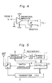
- Fig. 5 of the accompanying drawings is a circuit diagram showing an example of the principal part of a conventional transceiver.
- reference numeral 1 denotes a duplexer, 2 a receiver (Rx), 3 a transmitter (Tx), 4 a switch controller for the duplexer 1, 5 a controller and 9 a variable attenuator.
- the controller 5 controls the operation of the entire transceiver circuit and always detects the received input level by its internal logic IC and, when the received input level exceeds a given maximum level and the input level exceeds a normal level, the controller applies a control signal to the variable attenuator 8 to increase an attenuation value, putting the input level of the receiver 2 into the given range.
- variable attenuator 8 is provided at the input side of the receiver 2 and its attenuation value is controlled automatically or semi-automatically to preventthe reproduced speech quality from being impaired when the input is excessive.
- variable attenuator 8 is formed as an electronic variable attenuator using an FET or PIN diode and is very effective for an over input level, but when the received input level is so low as to reach the critical level, that is, when the attenuation value by the variable attenuator 8 is minimum, it provides an attenuation (an insertion loss) of about 1 to 2 dB, causing an increase in the noise figure of the receiver. Consequently, the receiving sensitivity decreases in correspondence to the insertion loss so that the synchronizing operation becomes unstable, reducing the service area.
- An object of the present invention is to provide a radio transceiver of the TDMA-TDD system which maintains its service area by avoiding reduction of the receiving sensitivity by the variable attenuator when the received level is low and which prevents the deterioration of the reproduced speech quality and the occurrence of the state of reception being impossible when the input level exceeds a normal level.
- the radio transceiver according to the present invention which is of the type wherein a transmitter and a receiver are connected via a duplexerto an antenna and a controller for controlling the entire transceiver operation controls the duplexerto be switched to either the transmitter or receiver, is characterized in that the controller has a construction wherein during transmission it activates the duplexer to switch the antenna to the transmitter; during reception it activates the duplexer to switch the antenna to the receiver, and when the received input level exceeds a predetermined maximum input level of the receiver, it activates the duplexer to switch the antenna to the transmitter to provide a leakage received power of the duplexer to the input of the receiver.
- reference numerals 1 through 5 denote the same parts as those in the prior art example of Fig. 5.
- This embodiment differs from the conventional arrangement of Fig. 5 in that the variable attenuator 8 which causes an insertion loss is omitted and in that the switching control operation of the duplexer 1 by the switch controller 4 differs from that in the prior art.
- Reference numeral 6 denotes an isolator provided in the transmitter 3 and 7 a termination.
- Fig. 2 is a circuit diagram showing an example of the duplexer 1. This is a circuit called an SPDT (Single Pole Double Threw) switch.
- the present invention does not employ the conventional variable attenuator which decreases the receiving sensitivity.
- the duplexer 1 is switched (S 3 ) by the switching controller 4 to the transmitter (Tx side).
- a receiving state that is, when RSSI (Receiving Signal Strength Indicator) level exceeds an allowable maximum value (i.e. a threshold level a) of the received input level range (S 2 ) which is, for example, 70 dB/ ⁇ V
- the duplexer 1 is switched (S 3 ) by the switching controller 4 to the transmitter (Tx side).
- the radio frequency band of the radiowave transmission section of the digital cordless telephone system for example, in 1 to 2 GHz band, even if the duplexer circuit 1 depicted in Fig.
- the receiver 2 is switched to the transmitter (Tx) to turn OFF the receiver (Rx), the receiver is not completely cut off and has a certain backward loss of about 20 to 30 dB, and consequently, a signal attenuated by about 20 to 30 dB from the over-level input from the antenna (ANT) is input into the receiver 2, which is caused to perform its normal operation, thus maintaining the quality of reproduced speech unchanged.
- the duplexer 1 is connected to the transmitter during transmission and when the received input level exceeds a normal level and it is connected to the receiver when the received input level is below the allowable maximum level (S 4 ), that is, the RSSI level is below a threshold level b (b ⁇ a), atwhich the receiver performs its normal operation.
- the duplexer circuit can be formed into a terminated type or an open type.
- the open type circuit is an opened state when it is opened, but since a transmission line of a predetermined electrical length is provided at the transmitter and since the transmitter is terminated with the termination 7 of the isolator 6 of the transmitter 3, there is no fear of incurring abnormal oscillation and the leakage to the receiver is kept constant.
Landscapes
- Engineering & Computer Science (AREA)
- Computer Networks & Wireless Communication (AREA)
- Signal Processing (AREA)
- Transceivers (AREA)
Applications Claiming Priority (3)
| Application Number | Priority Date | Filing Date | Title |
|---|---|---|---|
| JP30797592 | 1992-10-22 | ||
| JP307975/92 | 1992-10-22 | ||
| JP30797592A JP3359944B2 (ja) | 1992-10-22 | 1992-10-22 | 無線送受信機 |
Publications (3)
| Publication Number | Publication Date |
|---|---|
| EP0594434A2 true EP0594434A2 (de) | 1994-04-27 |
| EP0594434A3 EP0594434A3 (de) | 1995-01-04 |
| EP0594434B1 EP0594434B1 (de) | 2001-01-17 |
Family
ID=17975408
Family Applications (1)
| Application Number | Title | Priority Date | Filing Date |
|---|---|---|---|
| EP93308390A Expired - Lifetime EP0594434B1 (de) | 1992-10-22 | 1993-10-21 | Funksender/Empfänger |
Country Status (4)
| Country | Link |
|---|---|
| US (1) | US5477532A (de) |
| EP (1) | EP0594434B1 (de) |
| JP (1) | JP3359944B2 (de) |
| DE (1) | DE69329872T2 (de) |
Cited By (6)
| Publication number | Priority date | Publication date | Assignee | Title |
|---|---|---|---|---|
| EP0625831A3 (en) * | 1993-05-21 | 1995-10-04 | Sony Corp | Radio receiver-transmitter apparatus. |
| EP0814570A3 (de) * | 1996-06-21 | 1999-01-20 | Nec Corporation | Funkempfänger mit Antennenschalter zur Verbesserung der Signalqualität |
| EP0914013A1 (de) * | 1997-10-17 | 1999-05-06 | Nortel Matra Cellular | Einrichtung und Verfahren zur Frequenzband-Abtastung in einem mobilen Übertragungssystem |
| EP0765044A3 (de) * | 1995-09-22 | 2003-07-09 | Nokia Corporation | Funktelefon in einem Zeitmultiplexsystem |
| RU2290765C2 (ru) * | 2004-12-16 | 2006-12-27 | Общество с ограниченной ответственностью "Центр Инновационных Технологий-ЭС" | Трубопроводная система связи |
| WO2016150484A1 (en) * | 2015-03-23 | 2016-09-29 | Telefonaktiebolaget Lm Ericsson (Publ) | A switch circuitry with integrated attenuator |
Families Citing this family (29)
| Publication number | Priority date | Publication date | Assignee | Title |
|---|---|---|---|---|
| US5701595A (en) * | 1995-05-04 | 1997-12-23 | Nippondenso Co., Ltd. | Half duplex RF transceiver having low transmit path signal loss |
| JP2700000B2 (ja) * | 1995-05-10 | 1998-01-19 | 日本電気株式会社 | 無線lanシステムの無線送受信機 |
| JPH08330996A (ja) * | 1995-05-30 | 1996-12-13 | Sony Corp | アンテナ共用器 |
| JPH09200021A (ja) * | 1996-01-22 | 1997-07-31 | Mitsubishi Electric Corp | 集積回路 |
| FR2745131A1 (fr) * | 1996-02-21 | 1997-08-22 | Philips Electronics Nv | Appareil de radio-telephonie multimode |
| JPH09331206A (ja) * | 1996-06-12 | 1997-12-22 | Saitama Nippon Denki Kk | Tdma方式用携帯電話機のアンテナ整合部 |
| JP2993443B2 (ja) * | 1996-10-31 | 1999-12-20 | 日本電気株式会社 | 通信装置 |
| CN1139273C (zh) * | 1997-06-27 | 2004-02-18 | 皇家菲利浦电子有限公司 | 具有低功耗和良好频谱规范的无线通信设备 |
| US6009314A (en) * | 1997-11-17 | 1999-12-28 | Telefonaktiebolaget L/M Ericsson | Monolithic high frequency antenna switch |
| US6002920A (en) * | 1998-05-19 | 1999-12-14 | Northrop Grumman Corporation | Method and device for modifying a radio frequency range of a radio transceiver |
| US6272327B1 (en) * | 1998-06-18 | 2001-08-07 | Lucent Technologies Inc. | High power wireless telephone with over-voltage protection |
| US6195535B1 (en) * | 1998-09-04 | 2001-02-27 | Lucent Technologies Inc. | High power wireless telephone with over-voltage protection disabling circuit |
| US7013305B2 (en) | 2001-10-01 | 2006-03-14 | International Business Machines Corporation | Managing the state of coupling facility structures, detecting by one or more systems coupled to the coupling facility, the suspended state of the duplexed command, detecting being independent of message exchange |
| CN1132326C (zh) * | 1999-02-24 | 2003-12-24 | 三菱电机株式会社 | 无线终端装置 |
| US6226275B1 (en) | 1999-08-25 | 2001-05-01 | Utstarcom, Inc. | Wide band high power ultralinear RF transreceiver |
| US20040063412A1 (en) * | 2002-09-26 | 2004-04-01 | Kim Hea Joung | Attenuation of a received radio frequency signal |
| JP2004135164A (ja) * | 2002-10-11 | 2004-04-30 | Oki Electric Ind Co Ltd | 送受信回路 |
| US20050255812A1 (en) * | 2004-05-17 | 2005-11-17 | Samsung Electronics Co., Ltd. | RF front-end apparatus in a TDD wireless communication system |
| US20060223464A1 (en) * | 2005-03-29 | 2006-10-05 | Frank Michael L | Method for switching a power amplifier |
| WO2007083861A1 (en) * | 2006-01-20 | 2007-07-26 | Kmw Inc. | Radio frequency switch |
| EP1830490B1 (de) * | 2006-03-03 | 2013-07-03 | Samsung Electronics Co., Ltd. | Vorrichtung und Verfahren zur Unterstützung eines Weiterleitungsdienstes in einem Multihop-Relay-Breitbandkommunikationssystem mit drahtlosem Zugang |
| JP4775051B2 (ja) * | 2006-03-17 | 2011-09-21 | パナソニック株式会社 | 無線受信回路、受信信号減衰方法および携帯無線電話機 |
| US8000270B2 (en) * | 2008-07-03 | 2011-08-16 | Embarq Holdings Company, Llc | Content downloading over TDM with download pausing |
| KR101628359B1 (ko) * | 2009-03-11 | 2016-06-08 | 엘지이노텍 주식회사 | Rf 통신장치 및 제어방법 |
| US8903332B2 (en) * | 2009-06-23 | 2014-12-02 | Silicon Laboratories Inc. | Circuit device and method of coupling to an antenna |
| US9184779B2 (en) * | 2011-07-22 | 2015-11-10 | Texas Instruments Incorporated | Dynamic medium switch in co-located PLC and RF networks |
| US9769594B2 (en) * | 2015-01-30 | 2017-09-19 | Cassia Networks Inc. | Methods, devices and systems for increasing wireless communication range |
| EP4250575A1 (de) * | 2022-03-24 | 2023-09-27 | Funkwerk Systems GmbH | Vorrichtung und verfahren zur datenübertragung |
| TWI894672B (zh) | 2023-11-03 | 2025-08-21 | 立積電子股份有限公司 | 波束切換系統、波束切換方法及天線裝置 |
Family Cites Families (3)
| Publication number | Priority date | Publication date | Assignee | Title |
|---|---|---|---|---|
| US4158814A (en) * | 1977-09-08 | 1979-06-19 | General Research Of Electronics, Inc. | Automatic overload protection system |
| US4525863A (en) * | 1983-10-19 | 1985-06-25 | Gte Laboratories Incorporated | Solid state transmit/receive switch |
| JPH0626320B2 (ja) * | 1986-04-09 | 1994-04-06 | 日本電気株式会社 | 無線送受信装置 |
-
1992
- 1992-10-22 JP JP30797592A patent/JP3359944B2/ja not_active Expired - Fee Related
-
1993
- 1993-10-15 US US08/139,515 patent/US5477532A/en not_active Expired - Fee Related
- 1993-10-21 DE DE69329872T patent/DE69329872T2/de not_active Expired - Fee Related
- 1993-10-21 EP EP93308390A patent/EP0594434B1/de not_active Expired - Lifetime
Cited By (9)
| Publication number | Priority date | Publication date | Assignee | Title |
|---|---|---|---|---|
| EP0625831A3 (en) * | 1993-05-21 | 1995-10-04 | Sony Corp | Radio receiver-transmitter apparatus. |
| US5548239A (en) * | 1993-05-21 | 1996-08-20 | Sony Corporation | Radio receiver-transmitter apparatus and signal changeover switch |
| EP0765044A3 (de) * | 1995-09-22 | 2003-07-09 | Nokia Corporation | Funktelefon in einem Zeitmultiplexsystem |
| EP0814570A3 (de) * | 1996-06-21 | 1999-01-20 | Nec Corporation | Funkempfänger mit Antennenschalter zur Verbesserung der Signalqualität |
| US6009316A (en) * | 1996-06-21 | 1999-12-28 | Nec Corporation | Receiver with an antenna switch, in which sensitivity and quality of reception is improved |
| EP0914013A1 (de) * | 1997-10-17 | 1999-05-06 | Nortel Matra Cellular | Einrichtung und Verfahren zur Frequenzband-Abtastung in einem mobilen Übertragungssystem |
| US6370356B2 (en) | 1997-10-17 | 2002-04-09 | Nortel Matra Cellular | Apparatus and method of providing a mobile communication system |
| RU2290765C2 (ru) * | 2004-12-16 | 2006-12-27 | Общество с ограниченной ответственностью "Центр Инновационных Технологий-ЭС" | Трубопроводная система связи |
| WO2016150484A1 (en) * | 2015-03-23 | 2016-09-29 | Telefonaktiebolaget Lm Ericsson (Publ) | A switch circuitry with integrated attenuator |
Also Published As
| Publication number | Publication date |
|---|---|
| JP3359944B2 (ja) | 2002-12-24 |
| US5477532A (en) | 1995-12-19 |
| DE69329872T2 (de) | 2001-05-31 |
| JPH06140959A (ja) | 1994-05-20 |
| EP0594434B1 (de) | 2001-01-17 |
| EP0594434A3 (de) | 1995-01-04 |
| DE69329872D1 (de) | 2001-02-22 |
Similar Documents
| Publication | Publication Date | Title |
|---|---|---|
| EP0594434B1 (de) | Funksender/Empfänger | |
| US4761822A (en) | Burst-mode two-way radio communications system | |
| KR100394931B1 (ko) | 송수신장치 | |
| US6272327B1 (en) | High power wireless telephone with over-voltage protection | |
| US6393301B1 (en) | Radio telephone system within a vehicle with enhanced safety features | |
| US6195562B1 (en) | System for limiting the transmitted power of a mobile communication means | |
| US6195535B1 (en) | High power wireless telephone with over-voltage protection disabling circuit | |
| US6381446B1 (en) | Controllable filter | |
| US7050828B2 (en) | Inter-system monitor function | |
| EP0460280B1 (de) | Schaltung zur Steuerung der Sendeleistung | |
| US6154639A (en) | Handsfree unit | |
| KR20040103313A (ko) | 통신 단말의 권외 판정 방법, 무선 통신 시스템 전환 방법및 통신 단말 | |
| KR920009382B1 (ko) | 무선전화장치 및 그 제어방법 | |
| AU750740B2 (en) | Reception method and receiver | |
| KR920010106B1 (ko) | 무선 회선 제어 방법 | |
| JPS60182228A (ja) | 無線電話装置 | |
| JPS63260228A (ja) | 無線端末 | |
| JP2737860B2 (ja) | コードレス電話機 | |
| KR100265586B1 (ko) | 이동 전화 시스템의 순방향 통화 채널 전력 제어 방법 | |
| JPS6231537B2 (de) | ||
| JPH10336068A (ja) | 無線通信機 | |
| KR200225477Y1 (ko) | 증폭기에 내장되는 신호 지연기 | |
| JP2000068867A (ja) | 無線電話方式と無線電話装置 | |
| KR20040103193A (ko) | 단말기의 최대 송신전력 조정방법 | |
| KR20010028877A (ko) | 무선교환기 시스템의 안테나 다이버시티의 자동 온/오프 방법 |
Legal Events
| Date | Code | Title | Description |
|---|---|---|---|
| PUAI | Public reference made under article 153(3) epc to a published international application that has entered the european phase |
Free format text: ORIGINAL CODE: 0009012 |
|
| AK | Designated contracting states |
Kind code of ref document: A2 Designated state(s): DE GB |
|
| PUAL | Search report despatched |
Free format text: ORIGINAL CODE: 0009013 |
|
| AK | Designated contracting states |
Kind code of ref document: A3 Designated state(s): DE GB |
|
| 17P | Request for examination filed |
Effective date: 19950321 |
|
| 17Q | First examination report despatched |
Effective date: 19980812 |
|
| GRAG | Despatch of communication of intention to grant |
Free format text: ORIGINAL CODE: EPIDOS AGRA |
|
| RIC1 | Information provided on ipc code assigned before grant |
Free format text: 6H 04B 1/56 A, 6H 04B 1/44 B |
|
| GRAG | Despatch of communication of intention to grant |
Free format text: ORIGINAL CODE: EPIDOS AGRA |
|
| GRAH | Despatch of communication of intention to grant a patent |
Free format text: ORIGINAL CODE: EPIDOS IGRA |
|
| GRAH | Despatch of communication of intention to grant a patent |
Free format text: ORIGINAL CODE: EPIDOS IGRA |
|
| GRAA | (expected) grant |
Free format text: ORIGINAL CODE: 0009210 |
|
| AK | Designated contracting states |
Kind code of ref document: B1 Designated state(s): DE GB |
|
| REF | Corresponds to: |
Ref document number: 69329872 Country of ref document: DE Date of ref document: 20010222 |
|
| EN | Fr: translation not filed | ||
| PLBE | No opposition filed within time limit |
Free format text: ORIGINAL CODE: 0009261 |
|
| REG | Reference to a national code |
Ref country code: GB Ref legal event code: IF02 |
|
| 26N | No opposition filed | ||
| PGFP | Annual fee paid to national office [announced via postgrant information from national office to epo] |
Ref country code: GB Payment date: 20031016 Year of fee payment: 11 |
|
| PGFP | Annual fee paid to national office [announced via postgrant information from national office to epo] |
Ref country code: DE Payment date: 20031030 Year of fee payment: 11 |
|
| PG25 | Lapsed in a contracting state [announced via postgrant information from national office to epo] |
Ref country code: GB Free format text: LAPSE BECAUSE OF NON-PAYMENT OF DUE FEES Effective date: 20041021 |
|
| PG25 | Lapsed in a contracting state [announced via postgrant information from national office to epo] |
Ref country code: DE Free format text: LAPSE BECAUSE OF NON-PAYMENT OF DUE FEES Effective date: 20050503 |
|
| GBPC | Gb: european patent ceased through non-payment of renewal fee |
Effective date: 20041021 |