EP0594471B1 - Magnetische Lesevorrichtung - Google Patents
Magnetische Lesevorrichtung Download PDFInfo
- Publication number
- EP0594471B1 EP0594471B1 EP93402235A EP93402235A EP0594471B1 EP 0594471 B1 EP0594471 B1 EP 0594471B1 EP 93402235 A EP93402235 A EP 93402235A EP 93402235 A EP93402235 A EP 93402235A EP 0594471 B1 EP0594471 B1 EP 0594471B1
- Authority
- EP
- European Patent Office
- Prior art keywords
- magnetic
- read
- magnetic field
- head
- layers
- Prior art date
- Legal status (The legal status is an assumption and is not a legal conclusion. Google has not performed a legal analysis and makes no representation as to the accuracy of the status listed.)
- Expired - Lifetime
Links
Images


Classifications
-
- G—PHYSICS
- G06—COMPUTING OR CALCULATING; COUNTING
- G06K—GRAPHICAL DATA READING; PRESENTATION OF DATA; RECORD CARRIERS; HANDLING RECORD CARRIERS
- G06K7/00—Methods or arrangements for sensing record carriers, e.g. for reading patterns
- G06K7/08—Methods or arrangements for sensing record carriers, e.g. for reading patterns by means detecting the change of an electrostatic or magnetic field, e.g. by detecting change of capacitance between electrodes
-
- G—PHYSICS
- G11—INFORMATION STORAGE
- G11B—INFORMATION STORAGE BASED ON RELATIVE MOVEMENT BETWEEN RECORD CARRIER AND TRANSDUCER
- G11B5/00—Recording by magnetisation or demagnetisation of a record carrier; Reproducing by magnetic means; Record carriers therefor
- G11B5/127—Structure or manufacture of heads, e.g. inductive
- G11B5/33—Structure or manufacture of flux-sensitive heads, i.e. for reproduction only; Combination of such heads with means for recording or erasing only
- G11B5/39—Structure or manufacture of flux-sensitive heads, i.e. for reproduction only; Combination of such heads with means for recording or erasing only using magneto-resistive devices or effects
-
- G—PHYSICS
- G11—INFORMATION STORAGE
- G11B—INFORMATION STORAGE BASED ON RELATIVE MOVEMENT BETWEEN RECORD CARRIER AND TRANSDUCER
- G11B11/00—Recording on or reproducing from the same record carrier wherein for these two operations the methods are covered by different main groups of groups G11B3/00 - G11B7/00 or by different subgroups of group G11B9/00; Record carriers therefor
- G11B11/10—Recording on or reproducing from the same record carrier wherein for these two operations the methods are covered by different main groups of groups G11B3/00 - G11B7/00 or by different subgroups of group G11B9/00; Record carriers therefor using recording by magnetic means or other means for magnetisation or demagnetisation of a record carrier, e.g. light induced spin magnetisation; Demagnetisation by thermal or stress means in the presence or not of an orienting magnetic field
- G11B11/105—Recording on or reproducing from the same record carrier wherein for these two operations the methods are covered by different main groups of groups G11B3/00 - G11B7/00 or by different subgroups of group G11B9/00; Record carriers therefor using recording by magnetic means or other means for magnetisation or demagnetisation of a record carrier, e.g. light induced spin magnetisation; Demagnetisation by thermal or stress means in the presence or not of an orienting magnetic field using a beam of light or a magnetic field for recording by change of magnetisation and a beam of light for reproducing, i.e. magneto-optical, e.g. light-induced thermomagnetic recording, spin magnetisation recording, Kerr or Faraday effect reproducing
- G11B11/10532—Heads
- G11B11/10541—Heads for reproducing
- G11B11/10543—Heads for reproducing using optical beam of radiation
- G11B11/10547—Heads for reproducing using optical beam of radiation interacting with the magnetisation of an intermediate transfer element, e.g. magnetic film, included in the head
-
- G—PHYSICS
- G11—INFORMATION STORAGE
- G11B—INFORMATION STORAGE BASED ON RELATIVE MOVEMENT BETWEEN RECORD CARRIER AND TRANSDUCER
- G11B5/00—Recording by magnetisation or demagnetisation of a record carrier; Reproducing by magnetic means; Record carriers therefor
- G11B5/127—Structure or manufacture of heads, e.g. inductive
- G11B5/33—Structure or manufacture of flux-sensitive heads, i.e. for reproduction only; Combination of such heads with means for recording or erasing only
- G11B5/332—Structure or manufacture of flux-sensitive heads, i.e. for reproduction only; Combination of such heads with means for recording or erasing only using thin films
Definitions
- the invention relates to a reading device. magnetic and in particular a support reading head magnetic recording. She finds an application preferred in a magnetic device reader computer or professional video recorders.
- the invention is applicable to a Kerr magneto-optical read head for linearize its operation.
- the reading can be magneto-optical and use the "Kerr" effect to read the data.
- the magneto-optical Kerr effect is a property of certain materials used in the sensor industry magnetic: a linearly polarized optical beam which reflects on the surface of a material with an effect Kerr sees its polarization direction rotate as a function of the flux magnetic present in the material, at the point of reflection.
- a Kerr effect read sensor is organized in two layers of magnetic material 1, 2 separated by an insulator not magnetic 3: this structure is optimized to channel the magnetic flux from information recorded on the media as shown in Figure 1a.
- zone 5 of the sensor it is in contact or almost in contact with a magnetic support 4 to read.
- a linearly polarized IF optical beam is reflected on one magnetic layers of the head and reading information is performed by detecting the polarization rotation of the reflected beam (Kerr effect) FR.
- a technique used to stabilize the domains of the layers magnetic in magneto-resistive sensors is to add on the head a magnetized layer which "anchors" the domains by its field.
- the invention therefore relates to a magnetic reading device for reading information tracks from a magnetic medium to a determined sampling frequency with read head comprising at least one magnetic layer comprising a zone of reading intended to be arranged in a direction not parallel to the direction of travel of the information tracks on the magnetic medium as well as means of induction in the reading area, of a field magnetic excitation, the reading area being such that it makes it possible to read a multitrack magnetic support, characterized in that the field magnetic excitation is an alternating magnetic field superimposed on the continuous magnetic field, this alternating magnetic field having a frequency equal to an even multiple of the sampling frequency.
- the invention consists of a field generator low amplitude alternating magnetic arranged near the head: this device homogenizes the Kerr reading layer from a magnetic point of view.
- this generator is represented by a device 6 inducing a superimposed alternating magnetic field (magnetic polarization) in zone 5 where the magnetic head is under the influence of a magnetic field to be detected.
- This device can take different forms, the main thing is that it induces a quasi-uniform magnetic field throughout the area 5. This is also necessary if the support is multitrack and that zone 5 makes it possible to read several pieces of information simultaneously recorded.
- this field induction device magnetic device was represented by device 6. However, this device can be placed in any other location so that induce a magnetic field in zone 5, such as 6 'or 6 "slots.
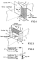
- Figure 4 shows an example of an embodiment applied to the reading of a magnetic tape. These measures includes the Kerr 10 effect read head itself corresponding to elements 1, 2, 3 of FIG. 3. The light beam of magnetic head reading has not been shown.
- the read head 10 is in contact (or almost in contact) with the magnetic medium to be read which scrolls regularly during reading.
- a solenoid 62 fitted with a ferrite core 6 located astride the read head generates an alternating field in the layers. This field, homogeneous throughout the active part of the sensor by the geometry of the ferrite, "shakes" the magnetic domains.
- the signal read from tape is affected by the magnetic non-linearities of the layers and by the reconfiguration noise areas previously described.
- the alternating field applied by the solenoid on the head causes a field which is superimposed on the useful signal from the media.
- the sensor then delivers a "carrier" signal to the frequency of the latter plus the useful signal from the band reread.
- the frequency of this request must be higher than the spectrum useful value of the re-read signal so that it can be filtered out.
- the zone 5 of the magnetic head 10 is located near a magnetic strip 4 to read.
- the induction device alternating magnetic field has two poles 60, 61 placed nearby of the magnetic head 10 so that the flux induced by the winding 62 closes with the magnetic head and in particular that the magnetic flux is induced in zone 5.
- the read head is oriented in a direction which is not parallel to the direction of travel of the strip.
- the active part of the magnetic head 10 is placed transversely to the direction of the strip and zone 5 allows several tracks to be played simultaneously.
- Poles 60, 61 are placed on the sides of the magnetic head transversely to the magnetic tape. In this way, a magnetic field AC (high frequency for example) is induced in the plane magnetic layers of the magnetic head and this in the zone 5 parallel to the plane of the magnetic strip.
- FIG. 5 represents an alternative embodiment of the device of FIG. 4.
- the magnetic circuit 6 and the head of reading by Kerr 10 effect are located on the same side of the support magnetic 4 to read.
- the bottom line is that the magnetic field alternative be applied parallel to the layer plane reading head and in zone 5 subject to magnetic field to be read on the magnetic support.
- the frequency of the polarization magnetic In case the sensor signal is sampled, it is advantageous to set the frequency of the polarization magnetic to an even multiple of the sampling frequency. Filtering is then naturally carried out due to the frequency synchronism, without aliasing.
- the frequency of the magnetic polarization could be 500 KHz or 1MHz for a sampling frequency of 50 KHz.
- AC polarization increases the signal to noise of the magneto-optical sensor in the useful band of frequencies.
- the gain in signal to noise ratio is 2 to 3 dB, in depending on the frequency of the signal read back.
- the square waveform for magnetic polarization achieves a better signal-to-noise ratio than the wave sinusoidal.
- the polarization magnetic promotes the propagation of the field in the layers, and the adjustment of the optical elements becomes less sharp, so easier to achieve.
- the invention has been applied to a magneto-optical read head using the effect Kerr. However, it is also applicable to any other head of reading in which a light beam has its characteristics modified by the magnetic field.
- the object essential is to provide an additional magnetic field whose role is to stabilize the magnetic layers.
- the invention is applicable to all types of magnetic heads in which there is a need to remedy instabilities or non-linearities of the head.
- it is applicable to all magnetic sensors made up of layers thin such as magneto-resistive heads.
- the technique currently used to stabilize magnetic thin layers of these sensors is to add on these a magnetized layer which makes the layers mono-magnetic domain. This continuous field allows stability magnetic layers at the expense of the sensitivity of the sensor.
Landscapes
- Engineering & Computer Science (AREA)
- Manufacturing & Machinery (AREA)
- Artificial Intelligence (AREA)
- Computer Vision & Pattern Recognition (AREA)
- Physics & Mathematics (AREA)
- General Physics & Mathematics (AREA)
- Theoretical Computer Science (AREA)
- Recording Or Reproducing By Magnetic Means (AREA)
- Magnetic Heads (AREA)
Claims (11)
- Magnetische Lesevorrichtung zum Auslesen von Informationsspuren eines magnetischen Aufzeichnungsträgers gemäß einer bestimmten Tastfrequenz, mit einem Lesekopf, der mindestens eine Magnetschicht (1, 2) mit einer Lesezone (5) enthält, die gemäß einer zur Durchlaufrichtung der Informationsspuren des magnetischen Aufzeichnungsträgers nicht parallelen Richtung angeordnet ist, sowie mit Mitteln (6) zur Induktion eines magnetischen Anregungsfelds in der Lesezone (5), wobei die Lesezone (5) so ausgebildet ist, daß sie das Auslesen eines magnetischen Mehrspur-Aufzeichnungsträgers erlaubt, dadurch gekennzeichnet, daß das magnetische Anregungsfeld ein magnetisches Wechselfeld ist, das dem magnetischen Gleichfeld überlagert ist und eine Frequenz besitzt, die ein geradzahliges Vielfaches der Tastfrequenz ist.
- Vorrichtung nach Anspruch 1, dadurch gekennzeichnet, daß der magnetische Aufzeichnungsträger ein Magnetband ist.
- Vorrichtung nach Anspruch 1, dadurch gekennzeichnet, daß der Lesekopf ein magneto-optischer Kopf ist, in dem ein Lese-Lichtstrahl in seinen Eigenschaften durch ein Magnetfeld verändert wird, wobei die Lesezone (5) den Lese-Lichtstrahl (FI) empfängt und einen reflektierten Strahl (FR) aussendet.
- Vorrichtung nach Anspruch 3, dadurch gekennzeichnet, daß der Lesekopf ein magneto-optischer Kopf mit Kerr-Effekt ist, der zwei Schichten aus magnetischen Materialien (1, 2) getrennt durch eine unmagnetische Spaltschicht (3) aufweist und die Lesezone (5) enthält, die in einem zu erfassenden Magnetfeld liegen soll, und daß der Lese-Lichtstrahl (FI) polarisiert ist und an einer der Magnetschichten (1, 2) reflektiert wird, worauf ein Polarisations-Analysator den reflektierten Lichtstrahl (FR) empfängt und an einen Photodetektor überträgt.
- Vorrichtung nach Anspruch 4, dadurch gekennzeichnet, daß die Mittel (6) zur magnetischen Induktion einen Magnetkreis enthalten, der zwei an den beiden gegenüberliegenden Flanken der magnetischen Schichten liegende Endpole (60, 61) besitzt.
- Vorrichtung nach Anspruch 1, dadurch gekennzeichnet, daß die Mittel (6) zur Induktion des Magnetfelds das Magnetfeld gemäß einer Richtung induzieren, die in der Ebene der magnetischen Schichten des Lesekopfes ausgerichtet ist.
- Vorrichtung nach Anspruch 4, dadurch gekennzeichnet, daß sie zum Lesen von Informationen von einem Magnetband bestimmt ist und daß die magnetischen Schichten des Lesekopfes eine Lesezone (5) in der Nähe des Magnetbands besitzen.
- Vorrichtung nach Anspruch 1, dadurch gekennzeichnet, daß sie zum Lesen von in einer Zeile angeordneten Informationen bestimmt ist und daß die Lesezone (5) ebenfalls die Form einer Zeile parallel zur Zeile von Informationen besitzt.
- Vorrichtung nach Anspruch 2, dadurch gekennzeichnet, daß die Mittel (6) zur Induktion eines Magnetfelds eine Spule (62) zur Induktion des Magnetfelds enthalten, die von einem Wechselstromgenerator (G2) mit Wechselstrom gespeist wird.
- Vorrichtung nach Anspruch 9, dadurch gekennzeichnet, daß die Spule (62) auch mit einem Gleichstrom gespeist wird, die von einem Gleichstromgenerator (G1) stammt.
- Vorrichtung nach Anspruch 2, dadurch gekennzeichnet, daß das magnetische Wechselsignal, das durch die Induktionsmittel (6) induziert wir, Rechteckform besitzt.
Applications Claiming Priority (2)
| Application Number | Priority Date | Filing Date | Title |
|---|---|---|---|
| FR9211146A FR2696037B1 (fr) | 1992-09-18 | 1992-09-18 | Dispositif de lecture magnétique. |
| FR9211146 | 1992-09-18 |
Publications (3)
| Publication Number | Publication Date |
|---|---|
| EP0594471A2 EP0594471A2 (de) | 1994-04-27 |
| EP0594471A3 EP0594471A3 (en) | 1994-07-06 |
| EP0594471B1 true EP0594471B1 (de) | 2003-03-05 |
Family
ID=9433653
Family Applications (1)
| Application Number | Title | Priority Date | Filing Date |
|---|---|---|---|
| EP93402235A Expired - Lifetime EP0594471B1 (de) | 1992-09-18 | 1993-09-14 | Magnetische Lesevorrichtung |
Country Status (6)
| Country | Link |
|---|---|
| US (1) | US5568336A (de) |
| EP (1) | EP0594471B1 (de) |
| JP (1) | JP4021944B2 (de) |
| KR (1) | KR100320484B1 (de) |
| DE (1) | DE69332734T2 (de) |
| FR (1) | FR2696037B1 (de) |
Families Citing this family (7)
| Publication number | Priority date | Publication date | Assignee | Title |
|---|---|---|---|---|
| US6327227B1 (en) * | 1997-08-08 | 2001-12-04 | Sharp Kabushiki Kaisha | Magnetic recorder/reproduction apparatus including a selective temperature controller and magnetic recording reproduction method including selective temperature control |
| US6380735B1 (en) | 1999-04-30 | 2002-04-30 | Sumitomo Special Metals Co., Ltd. | Orthogonal flux-gate type magnetic sensor |
| FR2797514B3 (fr) * | 1999-08-10 | 2001-10-12 | Thomson Csf | Dispositif de lecture magneto-optique pour bandes magnetiques multipistes |
| FR2802696B1 (fr) | 1999-12-17 | 2002-07-19 | Thomson Csf | Lecteur magneto optique optimise par le polariseur de lumiere incidente |
| US6771567B2 (en) | 2001-11-06 | 2004-08-03 | O-Mass As | Dual shield vertical magneto-optical read head |
| KR100464641B1 (ko) * | 2002-04-10 | 2005-01-03 | 가람테크(주) | 섬유분섬을 이용한 복합재료 제조방법 및 그 제조장치 |
| DE102004025937A1 (de) * | 2004-05-27 | 2005-12-22 | Giesecke & Devrient Gmbh | Vorrichtung und Verfahren zur Untersuchung von magnetichen Eigenschaften von Objekten |
Citations (1)
| Publication number | Priority date | Publication date | Assignee | Title |
|---|---|---|---|---|
| EP0436424A1 (de) * | 1989-12-28 | 1991-07-10 | THOMSON multimedia | Magnetooptischer Lesekopf |
Family Cites Families (14)
| Publication number | Priority date | Publication date | Assignee | Title |
|---|---|---|---|---|
| NL276507A (de) * | 1961-04-03 | |||
| US3513457A (en) * | 1962-12-12 | 1970-05-19 | Magnavox Co | Magneto-optical transducing system |
| US3701133A (en) * | 1967-05-05 | 1972-10-24 | Philip Smaller | Modulated magnetooptic readout system |
| US3665431A (en) * | 1970-06-25 | 1972-05-23 | Ibm | Magneto-optic transducer |
| JPS5421315A (en) * | 1977-07-18 | 1979-02-17 | Mitsubishi Electric Corp | Magnetic recorder |
| NL192546C (nl) * | 1982-07-19 | 1997-09-02 | Nippon Telegraph & Telephone | Leeskop voor een met hoge dichtheid uitgevoerde magnetische registratie. |
| US4703378A (en) * | 1984-03-01 | 1987-10-27 | Sony Corporation | Magnetic transducer head utilizing magnetoresistance effect |
| JPS60223043A (ja) * | 1984-04-20 | 1985-11-07 | Nippon Telegr & Teleph Corp <Ntt> | マイクロ磁気ヘツド |
| JPS60223042A (ja) * | 1984-04-20 | 1985-11-07 | Nippon Telegr & Teleph Corp <Ntt> | マイクロ磁気ヘツド |
| JPS61214260A (ja) * | 1985-03-20 | 1986-09-24 | Hitachi Ltd | 光再生磁気ヘツド |
| JPS61253619A (ja) * | 1985-05-07 | 1986-11-11 | Hitachi Ltd | 磁気抵抗効果型再生ヘツド |
| JPS61280013A (ja) * | 1985-06-05 | 1986-12-10 | Hitachi Ltd | 磁気抵抗効果型再生ヘツド |
| JPS6246418A (ja) * | 1985-08-23 | 1987-02-28 | Nippon Telegr & Teleph Corp <Ntt> | バイアス印加型磁気ヘツド |
| FR2652670B1 (fr) * | 1989-10-03 | 1995-06-23 | Thomson Csf | Tete de lecture magnetooptique a haute resolution. |
-
1992
- 1992-09-18 FR FR9211146A patent/FR2696037B1/fr not_active Expired - Lifetime
-
1993
- 1993-09-14 DE DE69332734T patent/DE69332734T2/de not_active Expired - Lifetime
- 1993-09-14 EP EP93402235A patent/EP0594471B1/de not_active Expired - Lifetime
- 1993-09-17 JP JP23164693A patent/JP4021944B2/ja not_active Expired - Lifetime
- 1993-09-17 KR KR1019930018779A patent/KR100320484B1/ko not_active Expired - Lifetime
-
1995
- 1995-03-10 US US08/402,392 patent/US5568336A/en not_active Expired - Lifetime
Patent Citations (1)
| Publication number | Priority date | Publication date | Assignee | Title |
|---|---|---|---|---|
| EP0436424A1 (de) * | 1989-12-28 | 1991-07-10 | THOMSON multimedia | Magnetooptischer Lesekopf |
Also Published As
| Publication number | Publication date |
|---|---|
| DE69332734T2 (de) | 2003-11-13 |
| EP0594471A2 (de) | 1994-04-27 |
| DE69332734D1 (de) | 2003-04-10 |
| KR100320484B1 (ko) | 2002-03-21 |
| JPH06195788A (ja) | 1994-07-15 |
| EP0594471A3 (en) | 1994-07-06 |
| US5568336A (en) | 1996-10-22 |
| KR950009491A (ko) | 1995-04-24 |
| JP4021944B2 (ja) | 2007-12-12 |
| FR2696037A1 (fr) | 1994-03-25 |
| FR2696037B1 (fr) | 1994-11-04 |
Similar Documents
| Publication | Publication Date | Title |
|---|---|---|
| US4228473A (en) | Pick-up device for magnetically recorded information and method and system for using same | |
| EP0107589B1 (de) | Vorrichtung zum Aufzeichnen von Informationen auf einem magnetischen Träger | |
| NL192546C (nl) | Leeskop voor een met hoge dichtheid uitgevoerde magnetische registratie. | |
| US4677512A (en) | Magnetic reproducing apparatus | |
| EP0061363B1 (de) | Magnetoresistiver Lesewandler für grosse Informationsdichtheit | |
| EP0594471A2 (de) | Magnetische Lesevorrichtung | |
| US5726964A (en) | Scanning head including a magneto-optical element and scanning device including the scanning head | |
| FR2499746A1 (fr) | Tete d'enregistrement/lecture magneto-optique | |
| US3445833A (en) | Signal responsive apparatus with a polar azimuth vibrator | |
| US5838444A (en) | Magneto-optic characteristic measuring apparatus | |
| US4677513A (en) | Magneto-optic thin film head and method of use | |
| FR2601465A1 (fr) | Dispositif modulateur haute frequence de polarisation de la lumiere | |
| FR2494952A1 (fr) | Transducteur magnetoresistant de lecture d'un support d'enregistrement a haute densite d'informations | |
| WO2021084169A1 (fr) | Dispositif de mesure d'une quantite de materiau superparamagnetique et utilisation d'un tel dispositif | |
| Jeffers et al. | Unshielded magnetoresistive heads in very high-density recording | |
| Akiyama et al. | Magnetic read-out head using induced RF permeability variation | |
| FR2956241A1 (fr) | Dispositif de lecture magnetique | |
| Gardner et al. | Characteristics of a new high c/n magneto-optic media | |
| JPS5922295B2 (ja) | 磁気ヘツド | |
| Stek et al. | Some aspects of overwrite in thick magnetic media | |
| RU2055403C1 (ru) | Способ магнитной записи-воспроизведения информации на движущийся носитель | |
| FR2463482A1 (fr) | Controle de l'enregistrement video par des tetes fixes | |
| Treves et al. | Magneto‐Optic Readout Using Media Modulation | |
| Van Kesteren et al. | Thin-film heads with anisotropy-determined track widths | |
| Castera et al. | Optical Readout Of Magnetic Tapes |
Legal Events
| Date | Code | Title | Description |
|---|---|---|---|
| PUAI | Public reference made under article 153(3) epc to a published international application that has entered the european phase |
Free format text: ORIGINAL CODE: 0009012 |
|
| AK | Designated contracting states |
Kind code of ref document: A2 Designated state(s): CH DE GB IT LI NL |
|
| PUAL | Search report despatched |
Free format text: ORIGINAL CODE: 0009013 |
|
| AK | Designated contracting states |
Kind code of ref document: A3 Designated state(s): CH DE GB IT LI NL |
|
| 17P | Request for examination filed |
Effective date: 19941209 |
|
| 17Q | First examination report despatched |
Effective date: 19961205 |
|
| RAP1 | Party data changed (applicant data changed or rights of an application transferred) |
Owner name: THALES |
|
| GRAH | Despatch of communication of intention to grant a patent |
Free format text: ORIGINAL CODE: EPIDOS IGRA |
|
| GRAH | Despatch of communication of intention to grant a patent |
Free format text: ORIGINAL CODE: EPIDOS IGRA |
|
| GRAA | (expected) grant |
Free format text: ORIGINAL CODE: 0009210 |
|
| AK | Designated contracting states |
Designated state(s): CH DE GB IT LI NL |
|
| REG | Reference to a national code |
Ref country code: GB Ref legal event code: FG4D Free format text: NOT ENGLISH |
|
| REG | Reference to a national code |
Ref country code: CH Ref legal event code: EP |
|
| REF | Corresponds to: |
Ref document number: 69332734 Country of ref document: DE Date of ref document: 20030410 Kind code of ref document: P |
|
| GBT | Gb: translation of ep patent filed (gb section 77(6)(a)/1977) | ||
| PLBE | No opposition filed within time limit |
Free format text: ORIGINAL CODE: 0009261 |
|
| STAA | Information on the status of an ep patent application or granted ep patent |
Free format text: STATUS: NO OPPOSITION FILED WITHIN TIME LIMIT |
|
| 26N | No opposition filed |
Effective date: 20031208 |
|
| PGFP | Annual fee paid to national office [announced via postgrant information from national office to epo] |
Ref country code: NL Payment date: 20080903 Year of fee payment: 16 Ref country code: IT Payment date: 20080926 Year of fee payment: 16 |
|
| PGFP | Annual fee paid to national office [announced via postgrant information from national office to epo] |
Ref country code: CH Payment date: 20081002 Year of fee payment: 16 |
|
| REG | Reference to a national code |
Ref country code: NL Ref legal event code: V1 Effective date: 20100401 |
|
| REG | Reference to a national code |
Ref country code: CH Ref legal event code: PL |
|
| PG25 | Lapsed in a contracting state [announced via postgrant information from national office to epo] |
Ref country code: NL Free format text: LAPSE BECAUSE OF NON-PAYMENT OF DUE FEES Effective date: 20100401 |
|
| PG25 | Lapsed in a contracting state [announced via postgrant information from national office to epo] |
Ref country code: LI Free format text: LAPSE BECAUSE OF NON-PAYMENT OF DUE FEES Effective date: 20090930 Ref country code: CH Free format text: LAPSE BECAUSE OF NON-PAYMENT OF DUE FEES Effective date: 20090930 |
|
| PGFP | Annual fee paid to national office [announced via postgrant information from national office to epo] |
Ref country code: DE Payment date: 20100930 Year of fee payment: 18 |
|
| PG25 | Lapsed in a contracting state [announced via postgrant information from national office to epo] |
Ref country code: IT Free format text: LAPSE BECAUSE OF NON-PAYMENT OF DUE FEES Effective date: 20090914 |
|
| PGFP | Annual fee paid to national office [announced via postgrant information from national office to epo] |
Ref country code: GB Payment date: 20120829 Year of fee payment: 20 |
|
| REG | Reference to a national code |
Ref country code: DE Ref legal event code: R119 Ref document number: 69332734 Country of ref document: DE Effective date: 20130403 |
|
| PG25 | Lapsed in a contracting state [announced via postgrant information from national office to epo] |
Ref country code: DE Free format text: LAPSE BECAUSE OF NON-PAYMENT OF DUE FEES Effective date: 20130403 |
|
| REG | Reference to a national code |
Ref country code: GB Ref legal event code: PE20 Expiry date: 20130913 |
|
| PG25 | Lapsed in a contracting state [announced via postgrant information from national office to epo] |
Ref country code: GB Free format text: LAPSE BECAUSE OF EXPIRATION OF PROTECTION Effective date: 20130913 |