EP0594497A1 - Modul für Filtration, Trennung, Reinigung von Gasen oder Flüssigkeiten oder katalytischer Umwandlung - Google Patents
Modul für Filtration, Trennung, Reinigung von Gasen oder Flüssigkeiten oder katalytischer Umwandlung Download PDFInfo
- Publication number
- EP0594497A1 EP0594497A1 EP93402566A EP93402566A EP0594497A1 EP 0594497 A1 EP0594497 A1 EP 0594497A1 EP 93402566 A EP93402566 A EP 93402566A EP 93402566 A EP93402566 A EP 93402566A EP 0594497 A1 EP0594497 A1 EP 0594497A1
- Authority
- EP
- European Patent Office
- Prior art keywords
- ferrule
- casing
- module
- module according
- substantially cylindrical
- Prior art date
- Legal status (The legal status is an assumption and is not a legal conclusion. Google has not performed a legal analysis and makes no representation as to the accuracy of the status listed.)
- Granted
Links
Images


Classifications
-
- F—MECHANICAL ENGINEERING; LIGHTING; HEATING; WEAPONS; BLASTING
- F01—MACHINES OR ENGINES IN GENERAL; ENGINE PLANTS IN GENERAL; STEAM ENGINES
- F01N—GAS-FLOW SILENCERS OR EXHAUST APPARATUS FOR MACHINES OR ENGINES IN GENERAL; GAS-FLOW SILENCERS OR EXHAUST APPARATUS FOR INTERNAL-COMBUSTION ENGINES
- F01N3/00—Exhaust or silencing apparatus having means for purifying, rendering innocuous, or otherwise treating exhaust
- F01N3/02—Exhaust or silencing apparatus having means for purifying, rendering innocuous, or otherwise treating exhaust for cooling, or for removing solid constituents of, exhaust
- F01N3/021—Exhaust or silencing apparatus having means for purifying, rendering innocuous, or otherwise treating exhaust for cooling, or for removing solid constituents of, exhaust by means of filters
- F01N3/0217—Exhaust or silencing apparatus having means for purifying, rendering innocuous, or otherwise treating exhaust for cooling, or for removing solid constituents of, exhaust by means of filters the filtering elements having the form of hollow cylindrical bodies
-
- B—PERFORMING OPERATIONS; TRANSPORTING
- B01—PHYSICAL OR CHEMICAL PROCESSES OR APPARATUS IN GENERAL
- B01D—SEPARATION
- B01D29/00—Filters with filtering elements stationary during filtration, e.g. pressure or suction filters, not covered by groups B01D24/00 - B01D27/00; Filtering elements therefor
- B01D29/11—Filters with filtering elements stationary during filtration, e.g. pressure or suction filters, not covered by groups B01D24/00 - B01D27/00; Filtering elements therefor with bag, cage, hose, tube, sleeve or like filtering elements
- B01D29/31—Self-supporting filtering elements
-
- B—PERFORMING OPERATIONS; TRANSPORTING
- B01—PHYSICAL OR CHEMICAL PROCESSES OR APPARATUS IN GENERAL
- B01D—SEPARATION
- B01D35/00—Filtering devices having features not specifically covered by groups B01D24/00 - B01D33/00, or for applications not specifically covered by groups B01D24/00 - B01D33/00; Auxiliary devices for filtration; Filter housing constructions
- B01D35/005—Filters specially adapted for use in internal-combustion engine lubrication or fuel systems
-
- B—PERFORMING OPERATIONS; TRANSPORTING
- B01—PHYSICAL OR CHEMICAL PROCESSES OR APPARATUS IN GENERAL
- B01D—SEPARATION
- B01D35/00—Filtering devices having features not specifically covered by groups B01D24/00 - B01D33/00, or for applications not specifically covered by groups B01D24/00 - B01D33/00; Auxiliary devices for filtration; Filter housing constructions
- B01D35/02—Filters adapted for location in special places, e.g. pipe-lines, pumps, stop-cocks
-
- B—PERFORMING OPERATIONS; TRANSPORTING
- B01—PHYSICAL OR CHEMICAL PROCESSES OR APPARATUS IN GENERAL
- B01D—SEPARATION
- B01D53/00—Separation of gases or vapours; Recovering vapours of volatile solvents from gases; Chemical or biological purification of waste gases, e.g. engine exhaust gases, smoke, fumes, flue gases, aerosols
- B01D53/34—Chemical or biological purification of waste gases
- B01D53/92—Chemical or biological purification of waste gases of engine exhaust gases
- B01D53/94—Chemical or biological purification of waste gases of engine exhaust gases by catalytic processes
-
- F—MECHANICAL ENGINEERING; LIGHTING; HEATING; WEAPONS; BLASTING
- F01—MACHINES OR ENGINES IN GENERAL; ENGINE PLANTS IN GENERAL; STEAM ENGINES
- F01N—GAS-FLOW SILENCERS OR EXHAUST APPARATUS FOR MACHINES OR ENGINES IN GENERAL; GAS-FLOW SILENCERS OR EXHAUST APPARATUS FOR INTERNAL-COMBUSTION ENGINES
- F01N3/00—Exhaust or silencing apparatus having means for purifying, rendering innocuous, or otherwise treating exhaust
- F01N3/02—Exhaust or silencing apparatus having means for purifying, rendering innocuous, or otherwise treating exhaust for cooling, or for removing solid constituents of, exhaust
- F01N3/021—Exhaust or silencing apparatus having means for purifying, rendering innocuous, or otherwise treating exhaust for cooling, or for removing solid constituents of, exhaust by means of filters
- F01N3/022—Exhaust or silencing apparatus having means for purifying, rendering innocuous, or otherwise treating exhaust for cooling, or for removing solid constituents of, exhaust by means of filters characterised by specially adapted filtering structure, e.g. honeycomb, mesh or fibrous
-
- F—MECHANICAL ENGINEERING; LIGHTING; HEATING; WEAPONS; BLASTING
- F01—MACHINES OR ENGINES IN GENERAL; ENGINE PLANTS IN GENERAL; STEAM ENGINES
- F01N—GAS-FLOW SILENCERS OR EXHAUST APPARATUS FOR MACHINES OR ENGINES IN GENERAL; GAS-FLOW SILENCERS OR EXHAUST APPARATUS FOR INTERNAL-COMBUSTION ENGINES
- F01N3/00—Exhaust or silencing apparatus having means for purifying, rendering innocuous, or otherwise treating exhaust
- F01N3/08—Exhaust or silencing apparatus having means for purifying, rendering innocuous, or otherwise treating exhaust for rendering innocuous
- F01N3/10—Exhaust or silencing apparatus having means for purifying, rendering innocuous, or otherwise treating exhaust for rendering innocuous by thermal or catalytic conversion of noxious components of exhaust
- F01N3/24—Exhaust or silencing apparatus having means for purifying, rendering innocuous, or otherwise treating exhaust for rendering innocuous by thermal or catalytic conversion of noxious components of exhaust characterised by constructional aspects of converting apparatus
- F01N3/28—Construction of catalytic reactors
- F01N3/2839—Arrangements for mounting catalyst support in housing, e.g. with means for compensating thermal expansion or vibration
- F01N3/2875—Arrangements for mounting catalyst support in housing, e.g. with means for compensating thermal expansion or vibration by using elastic means, e.g. spring leaves, for retaining catalyst body in the housing
-
- B—PERFORMING OPERATIONS; TRANSPORTING
- B01—PHYSICAL OR CHEMICAL PROCESSES OR APPARATUS IN GENERAL
- B01D—SEPARATION
- B01D2201/00—Details relating to filtering apparatus
- B01D2201/40—Special measures for connecting different parts of the filter
- B01D2201/403—Special measures for connecting different parts of the filter allowing dilatation, e.g. by heat
-
- F—MECHANICAL ENGINEERING; LIGHTING; HEATING; WEAPONS; BLASTING
- F01—MACHINES OR ENGINES IN GENERAL; ENGINE PLANTS IN GENERAL; STEAM ENGINES
- F01N—GAS-FLOW SILENCERS OR EXHAUST APPARATUS FOR MACHINES OR ENGINES IN GENERAL; GAS-FLOW SILENCERS OR EXHAUST APPARATUS FOR INTERNAL-COMBUSTION ENGINES
- F01N2330/00—Structure of catalyst support or particle filter
- F01N2330/06—Ceramic, e.g. monoliths
-
- F—MECHANICAL ENGINEERING; LIGHTING; HEATING; WEAPONS; BLASTING
- F01—MACHINES OR ENGINES IN GENERAL; ENGINE PLANTS IN GENERAL; STEAM ENGINES
- F01N—GAS-FLOW SILENCERS OR EXHAUST APPARATUS FOR MACHINES OR ENGINES IN GENERAL; GAS-FLOW SILENCERS OR EXHAUST APPARATUS FOR INTERNAL-COMBUSTION ENGINES
- F01N2330/00—Structure of catalyst support or particle filter
- F01N2330/14—Sintered material
-
- Y—GENERAL TAGGING OF NEW TECHNOLOGICAL DEVELOPMENTS; GENERAL TAGGING OF CROSS-SECTIONAL TECHNOLOGIES SPANNING OVER SEVERAL SECTIONS OF THE IPC; TECHNICAL SUBJECTS COVERED BY FORMER USPC CROSS-REFERENCE ART COLLECTIONS [XRACs] AND DIGESTS
- Y02—TECHNOLOGIES OR APPLICATIONS FOR MITIGATION OR ADAPTATION AGAINST CLIMATE CHANGE
- Y02T—CLIMATE CHANGE MITIGATION TECHNOLOGIES RELATED TO TRANSPORTATION
- Y02T10/00—Road transport of goods or passengers
- Y02T10/10—Internal combustion engine [ICE] based vehicles
- Y02T10/12—Improving ICE efficiencies
-
- Y—GENERAL TAGGING OF NEW TECHNOLOGICAL DEVELOPMENTS; GENERAL TAGGING OF CROSS-SECTIONAL TECHNOLOGIES SPANNING OVER SEVERAL SECTIONS OF THE IPC; TECHNICAL SUBJECTS COVERED BY FORMER USPC CROSS-REFERENCE ART COLLECTIONS [XRACs] AND DIGESTS
- Y10—TECHNICAL SUBJECTS COVERED BY FORMER USPC
- Y10S—TECHNICAL SUBJECTS COVERED BY FORMER USPC CROSS-REFERENCE ART COLLECTIONS [XRACs] AND DIGESTS
- Y10S55/00—Gas separation
- Y10S55/30—Exhaust treatment
Definitions
- the present invention relates to a filtration, separation, gas or liquid purification or catalytic transformation module, comprising, in a casing, at least one rigid treatment element for purification or with a separation, filtration membrane, or catalytic transformation.
- a module may be intended for filtration, separation, or purification of liquids, but it applies very particularly to the filtration or purification of the gases used for example in the manufacture of semiconductors.
- Such a module must be able to operate at temperatures ranging from ambient temperature to several hundred degrees Celsius, either for the treatment of the fluid, or for the cleaning or regeneration of the treatment element or elements. Under the effect of temperature variations, there appear differences in expansion between the element and the casing which can reach several millimeters when the treatment element has a length of the order of a meter.
- the element-housing connection must be flexible enough to be able to deform in order to compensate for these expansion differences.
- the element-casing connection can be achieved by means of a polymeric or elastomeric seal, for example made of PTFE, EPDM, silicone, etc.
- a polymeric or elastomeric seal for example made of PTFE, EPDM, silicone, etc.
- the elasticity of the seal is used to compensate for expansion differences between the element and the housing.
- modules are known in which the connection of the element or elements with the casing is made by means of one or more metal parts, or ferrules, placed at the ends of the element.
- Each of these parts is firmly fixed on the one hand to the metal casing, on the other hand to the end of a treatment element by a solder or by a glass (or enamel).
- solders do not generally offer good resistance to corrosion by gases such as HCl, chlorides, bromides, etc. which are commonly used for the etching of integrated circuits.
- the glasses which have a good resistance to corrosion are generally those which do not include in their composition of fusible component at low temperature. These glasses therefore melt at high temperature.
- the assembly of the module by means of these glasses therefore requires bringing the entire module to high temperature, which is not always possible since there is a risk of damaging the treatment element (filter layer, catalyst, etc.) , or the metal of the ferrule.
- this glass solution is expensive, because it involves significant cooking means and a complex process.
- the object of the invention consists in producing a filtration module which can be used at high temperature without the risk of pollution, and capable of withstanding the thermal, mechanical and chemical constraints which are applied to it.
- Hooping consists in fitting a piece into a hoop, the inside diameter of the hoop being less than the outside diameter of the piece to be hooped by an amount called tightening.
- This bonding method, or tightening has the advantage of being free of any organic or inorganic bonding agent.
- Thermal hooping consists, for example, in fitting the element into the shell after expansion of the latter by heating.
- Mechanical shrinking, or force fitting consists for example of cold pressing the element into the shell using a press.
- the advantage of the thermal hooping of the element in the shell is that there is tightening as long as the operating temperature of the module remains below the relaxation temperature of the metal (i.e. the temperature below of which it remains elastic) and of the temperature (if there is one) at which the thermal expansion of the metal and of the end of the element would cancel the tightening.
- the ferrule exerts a radial clamping force on a substantially cylindrical surface of the element.
- This clamping force is so high that no relative movement of the shell on the element is possible.
- the intensity of the force is related to the width of the cylindrical surface.
- the radial clamping force can be adjusted by modifying the width of the contact surface between the ferrule and the treatment element: the wider the contact strip, the more intense the clamping, without this modifying the longitudinal flexibility of the ferrule.
- connection between the ferrule and the element does not allow any relative movement of the ferrule relative to the element. Indeed any friction movement generates particles.
- One of the objects of the invention is to be able to use the module for the treatment of ultra-pure fluids without impurities being introduced, in particular by the generation of particles.
- connection between said element and said ferrule is produced by mechanical shrinking, or force fitting, of Walrus cones.
- the active element the geometry of the tip of which is slightly conical, of the Morses cone type (conicity - 5%)
- the shell the shaping of which is of the same geometry.
- said ferrule is elastically deformable, so that it can deform slightly parallel to the longitudinal axis of the module while behaving like a metal bellows.
- the treatment element is made of a material with fragile mechanical behavior (ceramic, glass, carbon, etc.)
- the mounting with the bellows-shaped ferrule protects the element against impact by its elasticity any received by the housing.
- Said ferrule is made of a material chosen from stainless steel, a titanium alloy of the TA6V type from the company PECHINEY, a nickel-rich alloy such as N42 or the Dilver (PO or P1) from the company IMPHY, or Kovar. from the company WES-TINGHOUSE, or even an alloy known under the registered trademark "HASTELLOY". These alloys are chosen because of their coefficient of expansion, their high stress relaxation temperature, and their resistance to corrosion.
- said ferrule is fixed to said casing by a weld produced by fitting the outer edge of said ferrule into a housing machined in the wall of said casing, and partial melting of the thickness of the wall of said casing and of the outer edge of said ferrule without a molten metal zone appearing on the inner surface of said casing.
- the ferrule and the housing part or parts are assembled by T.I.G. (Tungsten Inert Gas).
- T.I.G. Tungsten Inert Gas
- the tungsten electrode and all of the parts to be welded are rotated relative to each other around the axis of the housing to be assembled, which allows the depth of the area to be controlled.
- fondue (of the order of 4mm) relative to the thickness of the wall (5 to 7mm).
- a large weld bead is obtained (approximately 0.5 mm).
- said ferrule is fixed to said casing by a weld produced by fitting the outer edge of said ferrule into a housing machined in the wall of said casing, and partial melting of the thickness of the wall of said casing without fusion from the outer edge of said ferrule but with pinching of said edge by withdrawal of the molten zone, and without any zone of molten metal appearing on the internal surface of said casing.
- Pinching by removing the weld ensures between the casing and the ferrule a connection which is both mechanically very solid and absolutely watertight.
- This method has the advantage that to assemble the module, just two welds if there are two ferrules, or a single weld if there is only one ferrule.
- An advantage of the module according to the present invention is that its assembly is designed so that the connections made are sealed. This is the connection between the ferrule and the casing, but also the connection between the ferrule and the element (or its end piece) whose tightness is ensured by the tight tolerances of the dimensions of the parts as well as by the low roughness of their surface.
- connection between the ferrule and the casing could also be carried out by expansion, or by hooping the casing on the ferrule.
- At least one of the ends of said element is connected to said ferrule by means of a nozzle fixed to said element, said nozzle being of substantially cylindrical shape and made of a material chosen according to the function of said nozzle, from a porous material and a dense material.
- the tip is fixed to the treatment element either by a link devoid of any binder (thermal shrinking, force fitting, swaging, ...), or using a glass, or enamel, high fuse temperature.
- a glass or enamel, high fuse temperature.
- the use of a glass is possible without damaging the element because the connection between the element and the end piece is generally carried out before the coating of the support of the element with a membrane or a catalytic material for example .
- Only high temperature glass has properties that make it usable at high temperature without risk of pollution, and capable of withstanding the thermal, mechanical, and chemical constraints that are applied to the module.
- said element contains compounds which can react chemically with certain constituents (for example impurities) of the fluid to be treated to fix them, or denature them.
- said module comprises a multichannel treatment element with a membrane of the sterilizing type, with a hydrophobic surface, and the mean pore diameter of which is less than or equal to 0.8 micrometer.
- said module comprises a treatment element made of a porous material, carrying at each end an end piece of dense material made of a material of the same nature as said element, said end piece being linked by hooping to a alloy ferrule chosen from alloys rich in nickel, and said ferrule being welded to said stainless steel casing, the interior of which is electropolished.
- said module comprises a treatment element, chosen from the honeycomb type or the multi-channel type, made of dense material whose walls are coated with a catalytic material.
- a module according to the present invention has the advantage of being able to be used over a wide temperature range, and in particular at high temperatures (several hundred degrees Celsius), with or without thermal cycling. It also has the advantage of being free of any organic or inorganic bonding agent, capable of degrading over time or under the effect of thermal, mechanical or chemical stresses induced by the conditions of use.
- Another advantage of the module according to the present invention is that its internal surface is devoid of material capable of fixing and then restoring annoying impurities, such as organic materials, water vapor, or solid micro-particles which can be possibly contained in the gas to be treated. This advantage is particularly valuable in applications where the module must treat very pure gases.
- a module according to the invention is capable of numerous applications in the electronic, chemical, pharmaceutical, and food industry.
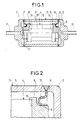
- the inlet and outlet of the fluid to be treated are made through orifices 11 and 12 located in the axis of the channel 16, at each end of the module.
- the passage of the fluid to be treated takes place from the external lateral surface of the treatment element 4 towards the internal surface of the channel 16.
- the circulation of the fluid takes place as follows: entry of the fluid by the orifice 12 at the end of the module, passage through orifice 10 in the shell 6, circulation along the external lateral surface of the element 4, crossing of the wall 18 of the element 4, circulation in the channel inside 16 towards the end 14 of the element 4, and exit by the orifice 17 then the orifice 11 at the other end of the module.
- FIG. 2 is an enlargement of the casing-ferrule-treatment element connection in FIG. 1.
- the treatment element 4 comprises an active central part which carries, at its end 15, the end piece 5.
- the ferrule 6 comes to tighten by hooping the cylindrical seat 9 located on the nozzle 5.
- the ferrule-casing junction is located on the lateral surface of the casing 13, at the junction of parts 2 and 3.
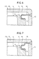
- Attaching the ferrule 6 to the casing 13 is carried out as follows (see FIGS. 3 and 4).
- a housing 19 is machined in parts 2 and 3 of the casing 13 so that the outer edge GEFH of the ferrule 6 fits there exactly as shown in Figure 3, which shows the parts before welding.
- the welding is carried out from the outside so as to melt only part of the thickness of the parts 2 and 3 of the casing 13 and to melt only the external edge EF of the ferrule 6 ; the melted area is represented in JMNK.
- the solidification of the molten zone is done with a shrinkage which strongly pinches the rim of the shell 6, the thickness MN, or PQ, then becoming significantly smaller than the initial thickness EF, or GH, of the shell 6.
- the pinching by the withdrawal of the weld ensures between the casing 13 and the ferrule 6 a connection which is both mechanically very solid and absolutely sealed.
- the ferrule-casing connection is made in such a way that no free surface 20 of molten metal appears inside the casing 13 during the welding operation.
- This method has the advantage of preventing on the one hand the emission of metal particles during this operation and the subsequent salting out of trapped particles, on the other hand the modification of the surface state around the weld zone by condensation of metal vaporized during the operation; finally, this method makes it possible to limit the molten zone to the external part of the thickness of the wall of the casing 13, ie approximately 4 mm for a total wall thickness of 5 to 7 mm.
- These filters or these porous elements can be of the membrane type, that is to say composed of a support with coarse porosity and one or more layers with fine porosity.
- FIG. 5 represents another variant of the crankcase-ferrule connection. Welding is carried out from the outside so as to melt only part of the thickness of the parts 2 and 3 of the casing 13, without there being any fusion of the external edge EF of the shell 6; the melted area is represented in JKL. The ferrule is held by the pinch due to the withdrawal of the molten zone which causes the housing 19 to tighten.
- the ferrule 66 is welded to the transverse surface of the casing 613, at the end of the module, at the junction of the parts 62 and 63 (FIG. 6).
- the ferrule 76 is welded at the intersection of the transverse and lateral surfaces of the casing 713, at the junction of the parts 72 and 73 (FIG. 7).
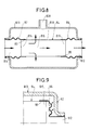
- FIG. 8 represents a module comprising a treatment element 84 provided with an internal channel 816 limited by a wall 818; each end 814 and 815 is connected respectively to each of the ferrules 87 and 86.
- the shrinking of the ferrules 86 and 87 is carried out directly on the cylindrical surface 89 of the processing element 84.
- the ferrules 86 and 87 are on the other hand welded to the transverse surface of the casing 813 at the inlet 811 and outlet 812 holes in the axis of the module.
- the casing 813 has a second outlet orifice 800 placed on its lateral face.
- This type of module works on the principle of tangential filtration.
- the fluid follows the path represented in FIG. 8 by arrows: the fluid to be treated enters the module through the orifice 811 which communicates with the end 814 of the element 84, and enters the internal channel 816 whose surface is covered or impregnated with a separation membrane. There is then separation of the fluid into two streams.
- a fraction of the fluid carries out the following path: tangential circulation on the internal surface of the internal channel 816 of the element 84, crossing of the wall 818 of the element 84 after exchange with the membrane, circulation along the external lateral surface of the element 84, output by the orifice 800 in the wall of the casing 813. Another part of the fluid circulates towards the other end 815 of the element 84, and leaves the module by the orifice 812.
- the treatment element 84 is of the cylindrical type made of porous carbon, coated with a microporous membrane (mean pore diameter: 1 nanometer); its ends 814 and 815 are covered with vitrified carbon and connected by shrinking respectively to the ferrules 87 and 86.
- the ferrules 86 and 87 in the form of a bellows, are made of titanium alloy of the TA6V type from PECHINEY with addition of 6% aluminum and 4% vanadium; this material is chosen for its thermomechanical characteristics and its good resistance to corrosion in environments not containing NaCI.
- the casing 813 is of identical composition, which solves the corrosion problem and facilitates the ferrule-casing assembly by welding.
- This mode of bonding by sintering carried out at a relatively low temperature compared to the sintering temperature of the membrane has the advantage of not causing any modification of the layers or membranes with which the element is coated. Such modifications can occur when methods such as the projection of molten material, of the metallic or ceramic schooping type, are used because of the heat transfer produced by the flame.
- membrane separators can be used to separate gases or liquids.
- This module is more particularly applicable, according to the principle of tangential filtration, to the extraction of asphaltenes from heavy fuel or residues under supercritical conditions of temperature (approximately 230 ° C.) and pressure (approximately 25 bars).
- This module can also be used for the recovery of cracking catalysts according to the same principle of tangential filtration by an element coated with a 0.2 ⁇ m membrane. The operating conditions in temperature and pressure are significantly higher than in the previous case.
- FIG. 9 a variant of the casing-ferrule-element connection has been shown where the assembly is carried out by a ferrule 96 hooped on the cylindrical surface 99 at the end 915 of the treatment element 94.
- This ferrule 96 is itself welded to the part 92, constituting the transverse surface of the casing 913, at the orifice 912 placed in the axis of the module
- connection is carried out by ferrules hooped on end pieces carried by the ends of the elements, these ferrules being themselves welded or expanded on a perforated plate serving as a cross section of the casing.
- This connection is applicable to separators, purifiers or filters. gas large, comprising several elements of a length of the order of a meter.
- FIG. 10 shows a gas purifier comprising a tubular element 104 with a porous wall 118, the internal channel 116 of which contains constituents 100 which react chemically with certain impurities in the gas to fix or denature them.
- Each end 114 and 115 of the element 104 has a cylindrical bearing surface 109 on which ferrules 107 and 106 are fixed by shrinking bellows in Hastelloy C22.
- the ferrule 107 has an orifice 119 for the passage of gas.
- These ferrules 106 and 107 are themselves welded to the casing 113 made of the same material C22.
- In the axis of the module is an inlet port 112 and an outlet port 111 for the gas.
- the gas flow in the module is represented by arrows.
- the gas to be treated enters the module through the orifice 112, scans the reactive medium 100 located in the internal channel 116 of the element 104, crosses the porous wall 118 of the element 104, then the treated gas leaves the module through the orifice 111, directly or after passing through the ferrule 107 through the orifice 119.
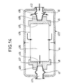
- a gas purifier of a different design is shown in Figure 11.
- the reactive constituents 500 are located outside of the porous member 504 which is in the form of a hollow cylinder having a porous wall 518 and an inner channel 516.
- Each end 514 and 515 of the element 504 is provided with an end piece 508 and 505.
- the end piece 505 serves as a plug for the channel 516, while the end piece 508 has an orifice 517 putting the channel 516 in communication with the outlet orifice 511 placed in the axis of the module.
- the entry into the module is made through the hole 512, also placed in the axis of the module, at the other end.
- Each end piece 505 and 508 has a cylindrical surface 509 on which a ferrule 506 and 507 is hooped.
- the ferrule 506 has an orifice 510 allowing the passage of gas.
- the ferrules 506 and 507 are on the other hand welded to the transverse surface of the casing 513 at the junction of the parts 51 and 53 and the parts 52 and 53.
- the gas to be treated penetrates through the orifice 512 of the module, crosses the ferrule 506 through the orifice 510, scans the reactive medium 500 located in the interval 50 separating the treatment element 504 from the casing 513, crosses the porous wall 518 of the element 504, circulates in the internal channel 516 of the element 504, and exits through the orifice 517 of the end piece 508 which communicates with the orifice 511 of the module outlet.
- the processing element 504 is made of porous ceramic, the end pieces 505 and 508 are made of dense ceramic, the ferrules 506 and 507 are made of Hastelloy C22.
- the housing 513 is made of the same material as the ferrules 506 and 507.
- This module also comprises a reactive product 500 which is composed of alumina particles coated with platinum located in the space 50 located between the element 504 and the housing 513.
- Such a separation module using a porous membrane retaining a catalyst bed can be used in the case of a catalytic reaction of gas, such as the hydrogenation of benzene which takes place around 260 ° C., the temperature at which the rate conversion rate is around 100%.
- gas such as the hydrogenation of benzene which takes place around 260 ° C., the temperature at which the rate conversion rate is around 100%.
- FIGS. 12a and 12b show an enlarged view of a ferrule-element junction in the case of an element 24, one of the ends 214 of which carries a nozzle 28.
- the element 24 is connected to two ferrules 26 and 27, one of the ferrules 26 is hooped directly on the end 215 of the element 24, the other ferrule 27 is hooped on the end piece 28 carried by the end 214 of the element 24.
- a single ferrule 26 is hooped directly on the end 215 of the element 24.
- Figures 13a and 13b show a type of ferrule-element connection by reverse hooping according to two alternative embodiments.
- end pieces 35 and 38 situated at each of its ends 314 and 315 of an element 34, are hooped on the cylindrical bearing surface 39 located on each of the ferrules 36 and 37.
- the fitting of a part, the ferrules 36 and 37 is carried out in a hoop represented here by the end pieces 35 and 38.
- the ferrules 36 and 37 are of on the other hand fixed in a direction perpendicular to the axis of the element.
- FIG. 13b shows the reverse hooping of two ferrules 336 and 337 in the end pieces 35 and 38 having a cylindrical bearing surface 39 placed at the ends 314 and 315 of the element 34
- the ferrules 336 and 337 are on the other hand fixed in a parallel direction to the axis of the element.
- FIG. 14 represents a module which comprises a tubular treatment element 44, having an internal channel 416 and a porous wall 418, connected by mechanical shrinking to ferrules 46 and 47 of slightly conical shape.
- the ferrule 46 has an orifice 410 allowing the passage of the fluid.
- the ends 414 and 415 of the element 44 are each provided with an end piece 45 and 48 whose bore is of the same geometry as the ferrules 46 and 47.
- the end piece 45 serves as a plug for the inner channel 416 of the element 44, while the end piece 48 is provided with an orifice 417 which places the internal channel 416 in communication with the orifice 411 for the output of the module.
- the hooping of the ends 45 and 48 on the conical surface 409 of the ferrules 46 and 47 is carried out by force fitting two cones, of the Morses cones type, that is to say with a half-angle at the top of about 1 , 5 degree.
- the ferrules 45 and 48 are on the other hand welded to the casing 413 at the inlet 412 and outlet 411 orifices located in the axis of the module.
- the fluid enters through the orifice 412, crosses the ferrule 46 through the orifice 410, circulates along the external lateral surface of the element 44, crosses the wall 418 and heads towards the end 414 by borrowing the internal channel416, finally, passing through the orifice 417 of the end piece 48, exits through the orifice 411 at the other end of the module.
Landscapes
- Chemical & Material Sciences (AREA)
- Engineering & Computer Science (AREA)
- Chemical Kinetics & Catalysis (AREA)
- Combustion & Propulsion (AREA)
- Mechanical Engineering (AREA)
- General Engineering & Computer Science (AREA)
- Health & Medical Sciences (AREA)
- Toxicology (AREA)
- Biomedical Technology (AREA)
- Environmental & Geological Engineering (AREA)
- Analytical Chemistry (AREA)
- General Chemical & Material Sciences (AREA)
- Oil, Petroleum & Natural Gas (AREA)
- Separation Using Semi-Permeable Membranes (AREA)
- Physical Or Chemical Processes And Apparatus (AREA)
- Filtering Of Dispersed Particles In Gases (AREA)
Applications Claiming Priority (2)
| Application Number | Priority Date | Filing Date | Title |
|---|---|---|---|
| FR9212535A FR2696947B1 (fr) | 1992-10-20 | 1992-10-20 | Module de filtration, de séparation, de purification de gaz ou de liquide, ou de transformation catalytique. |
| FR9212535 | 1992-10-20 |
Publications (2)
| Publication Number | Publication Date |
|---|---|
| EP0594497A1 true EP0594497A1 (de) | 1994-04-27 |
| EP0594497B1 EP0594497B1 (de) | 1997-04-02 |
Family
ID=9434700
Family Applications (1)
| Application Number | Title | Priority Date | Filing Date |
|---|---|---|---|
| EP93402566A Expired - Lifetime EP0594497B1 (de) | 1992-10-20 | 1993-10-19 | Modul für Filtration, Trennung, Reinigung von Gasen oder Flüssigkeiten oder katalytischer Umwandlung |
Country Status (8)
| Country | Link |
|---|---|
| US (2) | US5415772A (de) |
| EP (1) | EP0594497B1 (de) |
| JP (1) | JPH06262064A (de) |
| KR (1) | KR100306016B1 (de) |
| CN (1) | CN1035155C (de) |
| CA (1) | CA2108698C (de) |
| DE (1) | DE69309388T2 (de) |
| FR (1) | FR2696947B1 (de) |
Cited By (1)
| Publication number | Priority date | Publication date | Assignee | Title |
|---|---|---|---|---|
| WO2000040325A1 (de) * | 1999-01-08 | 2000-07-13 | Heggemann Gmbh | Membranmodul |
Families Citing this family (45)
| Publication number | Priority date | Publication date | Assignee | Title |
|---|---|---|---|---|
| US6338906B1 (en) | 1992-09-17 | 2002-01-15 | Coorstek, Inc. | Metal-infiltrated ceramic seal |
| US6247221B1 (en) * | 1992-09-17 | 2001-06-19 | Coors Tek, Inc. | Method for sealing and/or joining an end of a ceramic filter |
| US6143421A (en) * | 1992-09-17 | 2000-11-07 | Coorstek, Inc. | Electronic components incorporating ceramic-metal composites |
| US5700373A (en) * | 1992-09-17 | 1997-12-23 | Coors Ceramics Company | Method for sealing a filter |
| US5814164A (en) | 1994-11-09 | 1998-09-29 | American Scientific Materials Technologies L.P. | Thin-walled, monolithic iron oxide structures made from steels, and methods for manufacturing such structures |
| US5656245A (en) * | 1995-11-14 | 1997-08-12 | Nippon Reinz Co., Ltd. | Catalytic converter for cleaning exhaust gas |
| DE19621541C1 (de) * | 1996-05-29 | 1997-04-10 | Draegerwerk Ag | Beatmungsanfeuchter |
| US6033455A (en) * | 1996-07-19 | 2000-03-07 | 3M Innovative Properties Company | Repeatedly usable filter frame and filter for fluid using the same |
| USD399299S (en) | 1997-03-05 | 1998-10-06 | Ilan Zadok Golan | Liquid filter |
| US5917066A (en) * | 1997-07-16 | 1999-06-29 | Mott Metallurgical Corporation | Inline ultra-high efficiency filter |
| US6313953B1 (en) * | 1999-01-15 | 2001-11-06 | Donaldson Company, Inc. | Gas chemical filtering for optimal light transmittance; and methods |
| US6461562B1 (en) | 1999-02-17 | 2002-10-08 | American Scientific Materials Technologies, Lp | Methods of making sintered metal oxide articles |
| FR2805331B1 (fr) * | 2000-02-21 | 2002-05-31 | Ceramiques Tech Soc D | Element multicanal et procede de fabrication d'un tel element |
| US7052532B1 (en) | 2000-03-09 | 2006-05-30 | 3M Innovative Properties Company | High temperature nanofilter, system and method |
| US6669913B1 (en) | 2000-03-09 | 2003-12-30 | Fleetguard, Inc. | Combination catalytic converter and filter |
| US7211226B2 (en) * | 2000-03-09 | 2007-05-01 | Fleetgaurd, Inc. | Catalyst and filter combination |
| US6776814B2 (en) | 2000-03-09 | 2004-08-17 | Fleetguard, Inc. | Dual section exhaust aftertreatment filter and method |
| DE10026344A1 (de) * | 2000-04-01 | 2001-10-04 | Membraflow Gmbh & Co Kg Filter | Filtermodul |
| JP4715046B2 (ja) * | 2001-06-29 | 2011-07-06 | 日本無機株式会社 | ガスフィルタ装置 |
| US6638332B1 (en) * | 2001-10-31 | 2003-10-28 | Fleetguard, Inc. | Filter with multi-purpose end cap |
| US6814771B2 (en) * | 2001-11-30 | 2004-11-09 | Delphi Technologies, Inc. | Evaporative emissions control device with internal seals |
| US20040116276A1 (en) * | 2002-02-12 | 2004-06-17 | Aleksey Yezerets | Exhaust aftertreatment emission control regeneration |
| US6852219B2 (en) * | 2002-07-22 | 2005-02-08 | John M. Hammond | Fluid separation and delivery apparatus and method |
| DE10328188A1 (de) * | 2003-06-24 | 2005-01-13 | Robert Bosch Gmbh | Partikelfilter, insbesondere für Abgase von Brennkraftmaschinen |
| US7294162B2 (en) * | 2003-11-04 | 2007-11-13 | Donaldson Company, Inc. | Exhaust filter |
| US7169213B2 (en) * | 2004-10-29 | 2007-01-30 | Corning Incorporated | Multi-channel cross-flow porous device |
| US20060090649A1 (en) * | 2004-10-29 | 2006-05-04 | Wei Liu | High separation area membrane module |
| FR2878761A1 (fr) * | 2004-12-07 | 2006-06-09 | Patrick Fovez | Filtre a diatomites |
| DE502005001056D1 (de) * | 2005-04-01 | 2007-08-30 | Knuerr Ag | Lagerungs-Anordnung |
| US7445248B2 (en) * | 2006-01-06 | 2008-11-04 | Caterpillar Inc. | Thermal expansion joint |
| US7575616B2 (en) * | 2006-02-10 | 2009-08-18 | Entegris, Inc. | Low-profile surface mount filter |
| US7919052B2 (en) * | 2007-07-27 | 2011-04-05 | Silex Innovations Inc. | Securing catalyst element in catalytic converter with bolted bar |
| US8101010B2 (en) * | 2009-05-28 | 2012-01-24 | Corning Incorporated | Gas separation module |
| ES2575583T3 (es) * | 2010-03-12 | 2016-06-29 | Yanmar Co., Ltd. | Intercambiador de calor del gas de escape del motor y dispositivo de suministro de energía que lo utiliza |
| NL2009358A (en) | 2011-09-23 | 2013-03-26 | Asml Netherlands Bv | Radiation source. |
| US8875500B2 (en) | 2012-08-23 | 2014-11-04 | Electro-Motive Diesel, Inc. | Mounting foot for an after-treatment component |
| US9097168B2 (en) | 2012-08-23 | 2015-08-04 | Electro-Motive Diesel, Inc. | Bracket for an after-treatment component |
| US8943816B2 (en) | 2012-08-23 | 2015-02-03 | Electro-Motive Diesel, Inc. | Mounting system for an after-treatment component |
| CN105709570B (zh) * | 2014-12-05 | 2018-11-27 | 大连华海制氢设备有限公司 | 一种带膨胀节的氢气分离器 |
| WO2016153955A1 (en) | 2015-03-23 | 2016-09-29 | Corning Incorporated | Exhaust gas treatment article and methods of manufacturing same |
| WO2016182806A1 (en) | 2015-05-08 | 2016-11-17 | Corning Incorporated | Housing, fluid stream treatment article, exhaust system and methods of manufacturing same |
| EP3392512A1 (de) | 2017-04-19 | 2018-10-24 | HILTI Aktiengesellschaft | Befestigungsverfahren und befestigungssystem |
| CN115229457A (zh) * | 2022-09-19 | 2022-10-25 | 云南菲尔特环保科技股份有限公司 | 一种大小孔蜂窝结构体挤出模具的加工方法 |
| JP2025174528A (ja) * | 2024-05-17 | 2025-11-28 | カナデビア株式会社 | 被分離流体が流れる通路形成用の外管及びこれを用いた分離装置 |
| CN118750982B (zh) * | 2024-09-06 | 2024-11-05 | 东莞市博思特数控机械有限公司 | 一种机加工中心油雾分离装置 |
Citations (2)
| Publication number | Priority date | Publication date | Assignee | Title |
|---|---|---|---|---|
| US3841839A (en) * | 1972-11-17 | 1974-10-15 | Corning Glass Works | Catalytic converter |
| FR2392709A1 (fr) * | 1977-05-31 | 1978-12-29 | Engelhard Min & Chem | Appareil catalytique pour le traitement des gaz, en particulier des gaz d'echappement des moteurs a combustion interne |
Family Cites Families (9)
| Publication number | Priority date | Publication date | Assignee | Title |
|---|---|---|---|---|
| US3065941A (en) * | 1959-09-21 | 1962-11-27 | Henrite Products Corp | Motor mounting ring |
| DE2216772A1 (de) * | 1972-04-07 | 1973-10-18 | Kali Chemie Ag | Elastische halterung fuer keramische monolithische katalysatorkoerper |
| US4004888A (en) * | 1972-04-07 | 1977-01-25 | Kali-Chemie Aktiengesellschaft | Exhaust gas cleaning arrangement with a resiliently supported monolithic ceramic catalyzer |
| US3817714A (en) * | 1972-10-10 | 1974-06-18 | Corning Glass Works | Catalytic converter |
| DE2313166C3 (de) * | 1973-03-16 | 1978-06-22 | Daimler-Benz Ag, 7000 Stuttgart | Vorrichtung zur Halterung eines Katalysator-Monoliths |
| US4163041A (en) * | 1974-05-29 | 1979-07-31 | J. Eberspacher | Support for elastically mounting a ceramic honeycomb catalyst |
| US4155980A (en) * | 1976-06-19 | 1979-05-22 | Zeuna-Starker Kg | Apparatus for catalytic purifying the effluent gases of internal combustion engines |
| JPS6029623Y2 (ja) * | 1980-04-30 | 1985-09-06 | 本田技研工業株式会社 | モノリス型触媒担体の支承装置 |
| FR2658431B1 (fr) * | 1990-02-16 | 1992-04-30 | Ceramiques Tech Soc D | Dispositif a membrane pour filtration, separation ou reaction catalytique. |
-
1992
- 1992-10-20 FR FR9212535A patent/FR2696947B1/fr not_active Expired - Fee Related
- 1992-11-03 US US07/970,787 patent/US5415772A/en not_active Expired - Fee Related
-
1993
- 1993-10-19 CA CA002108698A patent/CA2108698C/fr not_active Expired - Fee Related
- 1993-10-19 KR KR1019930021655A patent/KR100306016B1/ko not_active Expired - Fee Related
- 1993-10-19 DE DE69309388T patent/DE69309388T2/de not_active Expired - Fee Related
- 1993-10-19 EP EP93402566A patent/EP0594497B1/de not_active Expired - Lifetime
- 1993-10-20 JP JP5262424A patent/JPH06262064A/ja active Pending
- 1993-10-20 CN CN93120384A patent/CN1035155C/zh not_active Expired - Fee Related
-
1994
- 1994-11-09 US US08/338,227 patent/US5468384A/en not_active Expired - Fee Related
Patent Citations (2)
| Publication number | Priority date | Publication date | Assignee | Title |
|---|---|---|---|---|
| US3841839A (en) * | 1972-11-17 | 1974-10-15 | Corning Glass Works | Catalytic converter |
| FR2392709A1 (fr) * | 1977-05-31 | 1978-12-29 | Engelhard Min & Chem | Appareil catalytique pour le traitement des gaz, en particulier des gaz d'echappement des moteurs a combustion interne |
Cited By (1)
| Publication number | Priority date | Publication date | Assignee | Title |
|---|---|---|---|---|
| WO2000040325A1 (de) * | 1999-01-08 | 2000-07-13 | Heggemann Gmbh | Membranmodul |
Also Published As
| Publication number | Publication date |
|---|---|
| KR940008722A (ko) | 1994-05-16 |
| DE69309388T2 (de) | 1997-07-31 |
| CN1035155C (zh) | 1997-06-18 |
| JPH06262064A (ja) | 1994-09-20 |
| CN1105601A (zh) | 1995-07-26 |
| FR2696947B1 (fr) | 1994-11-25 |
| US5468384A (en) | 1995-11-21 |
| CA2108698C (fr) | 1999-12-28 |
| FR2696947A1 (fr) | 1994-04-22 |
| KR100306016B1 (ko) | 2001-11-30 |
| CA2108698A1 (fr) | 1994-04-21 |
| EP0594497B1 (de) | 1997-04-02 |
| DE69309388D1 (de) | 1997-05-07 |
| US5415772A (en) | 1995-05-16 |
Similar Documents
| Publication | Publication Date | Title |
|---|---|---|
| EP0594497B1 (de) | Modul für Filtration, Trennung, Reinigung von Gasen oder Flüssigkeiten oder katalytischer Umwandlung | |
| EP2401245B1 (de) | Vorrichtung enthaltend ein beschichtetes keramikrohr und einen schrumpfring | |
| EP0547959B1 (de) | Reiniger für Wasserstoff mit einer Basis aus gleicher Legierung wie die Rohre | |
| EP0170025B1 (de) | Vorrichtung zur Montage eines rohrförmigen Filterelementes in einem Behälter | |
| FR2695838A1 (fr) | Assemblage formant filtre d'évent pouvant être monté sur un conteneur de déchets. | |
| EP2401540B1 (de) | Nachgiebiges material | |
| FR2942515A1 (fr) | Dispositif d'assemblage. | |
| FR2705693A1 (fr) | Procédé de fabrication d'un dispositif micro-usiné à contenir ou à véhiculer un fluide. | |
| FR2642328A1 (fr) | Procede d'assemblage dans un module d'un element rigide a membrane de separation, de filtration, ou de transformation catalytique | |
| EP0821996A1 (de) | Flüssigkeitsbehandlungsmodul mit steifer Membran und Gebrauchsverfahren desselben | |
| EP0999421B1 (de) | Vorrichtung und Verfahren zur Filtration für Kühlzyklus | |
| FR2942516A1 (fr) | Assemblage affleurant. | |
| EP1827670A1 (de) | Keramik-metall- oder metalllegierungsverbindungsanordnung | |
| EP0724960B1 (de) | Modulationsvorrichtung mit einem Sicherheitsfilter für einen Tintenstrahldruckkopf | |
| FR2698286A1 (fr) | Elément de filtre, son procédé de fabrication et appareil pour la mise en Óoeuvre de ce procédé. | |
| EP1701777A1 (de) | Verfahren zur montage einer gastrennmembran auf einem träger | |
| EP2516093B1 (de) | Lötverfahren für eine komponente eines klimaanlagenkreislaufes mit einer kältemittelaufnahme und derartige aufnahme | |
| FR2599896A1 (fr) | Procede pour solidariser par thermocompression un tube en alumine beta ou beta seconde et un support en ceramique isolante dans un generateur electrochimique sodium-soufre et generateurs electrochimiques en faisant application | |
| FR2942518A1 (fr) | Dispositif d'assemblage a distance. | |
| FR2942519A1 (fr) | Dispositif d'assemblage a bouclier. | |
| FR2925580A1 (fr) | Procede de fabrication d'un element de depollution pour ligne d'echappement | |
| EP1511550A2 (de) | Abgasfiltervorrichtung | |
| EP0689894A1 (de) | Verfahren-Vorrichtung zum Löten eines porösen metallischen Körper auf einem metallischen Warstück, und dafür hergestellter Filter | |
| BE880544A (fr) | Appareil pour filtrer l'oxygene gazeux ou d'autres gaz comprimes | |
| FR2944053A1 (fr) | Element de depollution de gaz d'echappement. |
Legal Events
| Date | Code | Title | Description |
|---|---|---|---|
| PUAI | Public reference made under article 153(3) epc to a published international application that has entered the european phase |
Free format text: ORIGINAL CODE: 0009012 |
|
| AK | Designated contracting states |
Kind code of ref document: A1 Designated state(s): AT BE CH DE FR GB IT LI NL |
|
| 17P | Request for examination filed |
Effective date: 19940827 |
|
| 17Q | First examination report despatched |
Effective date: 19950519 |
|
| GRAG | Despatch of communication of intention to grant |
Free format text: ORIGINAL CODE: EPIDOS AGRA |
|
| GRAH | Despatch of communication of intention to grant a patent |
Free format text: ORIGINAL CODE: EPIDOS IGRA |
|
| GRAH | Despatch of communication of intention to grant a patent |
Free format text: ORIGINAL CODE: EPIDOS IGRA |
|
| RBV | Designated contracting states (corrected) |
Designated state(s): CH DE FR GB IT LI NL |
|
| GRAA | (expected) grant |
Free format text: ORIGINAL CODE: 0009210 |
|
| AK | Designated contracting states |
Kind code of ref document: B1 Designated state(s): CH DE FR GB IT LI NL |
|
| REG | Reference to a national code |
Ref country code: CH Ref legal event code: EP |
|
| REF | Corresponds to: |
Ref document number: 69309388 Country of ref document: DE Date of ref document: 19970507 |
|
| GBT | Gb: translation of ep patent filed (gb section 77(6)(a)/1977) |
Effective date: 19970516 |
|
| REG | Reference to a national code |
Ref country code: CH Ref legal event code: NV Representative=s name: PATMED AG |
|
| PLBE | No opposition filed within time limit |
Free format text: ORIGINAL CODE: 0009261 |
|
| STAA | Information on the status of an ep patent application or granted ep patent |
Free format text: STATUS: NO OPPOSITION FILED WITHIN TIME LIMIT |
|
| 26N | No opposition filed | ||
| PGFP | Annual fee paid to national office [announced via postgrant information from national office to epo] |
Ref country code: NL Payment date: 20011029 Year of fee payment: 9 Ref country code: CH Payment date: 20011029 Year of fee payment: 9 |
|
| REG | Reference to a national code |
Ref country code: GB Ref legal event code: IF02 |
|
| PG25 | Lapsed in a contracting state [announced via postgrant information from national office to epo] |
Ref country code: LI Free format text: LAPSE BECAUSE OF NON-PAYMENT OF DUE FEES Effective date: 20021031 Ref country code: CH Free format text: LAPSE BECAUSE OF NON-PAYMENT OF DUE FEES Effective date: 20021031 |
|
| PG25 | Lapsed in a contracting state [announced via postgrant information from national office to epo] |
Ref country code: NL Free format text: LAPSE BECAUSE OF NON-PAYMENT OF DUE FEES Effective date: 20030501 |
|
| REG | Reference to a national code |
Ref country code: CH Ref legal event code: PL |
|
| NLV4 | Nl: lapsed or anulled due to non-payment of the annual fee |
Effective date: 20030501 |
|
| PGFP | Annual fee paid to national office [announced via postgrant information from national office to epo] |
Ref country code: FR Payment date: 20031003 Year of fee payment: 11 |
|
| PGFP | Annual fee paid to national office [announced via postgrant information from national office to epo] |
Ref country code: GB Payment date: 20031016 Year of fee payment: 11 |
|
| PGFP | Annual fee paid to national office [announced via postgrant information from national office to epo] |
Ref country code: DE Payment date: 20031030 Year of fee payment: 11 |
|
| PG25 | Lapsed in a contracting state [announced via postgrant information from national office to epo] |
Ref country code: GB Free format text: LAPSE BECAUSE OF NON-PAYMENT OF DUE FEES Effective date: 20041019 |
|
| PG25 | Lapsed in a contracting state [announced via postgrant information from national office to epo] |
Ref country code: DE Free format text: LAPSE BECAUSE OF NON-PAYMENT OF DUE FEES Effective date: 20050503 |
|
| GBPC | Gb: european patent ceased through non-payment of renewal fee |
Effective date: 20041019 |
|
| PG25 | Lapsed in a contracting state [announced via postgrant information from national office to epo] |
Ref country code: FR Free format text: LAPSE BECAUSE OF NON-PAYMENT OF DUE FEES Effective date: 20050630 |
|
| REG | Reference to a national code |
Ref country code: FR Ref legal event code: ST |
|
| PG25 | Lapsed in a contracting state [announced via postgrant information from national office to epo] |
Ref country code: IT Free format text: LAPSE BECAUSE OF NON-PAYMENT OF DUE FEES;WARNING: LAPSES OF ITALIAN PATENTS WITH EFFECTIVE DATE BEFORE 2007 MAY HAVE OCCURRED AT ANY TIME BEFORE 2007. THE CORRECT EFFECTIVE DATE MAY BE DIFFERENT FROM THE ONE RECORDED. Effective date: 20051019 |