EP0594533A2 - Méthode et dispositif de détection des tensions de matériaux dans les pièces préformées - Google Patents
Méthode et dispositif de détection des tensions de matériaux dans les pièces préformées Download PDFInfo
- Publication number
- EP0594533A2 EP0594533A2 EP93810688A EP93810688A EP0594533A2 EP 0594533 A2 EP0594533 A2 EP 0594533A2 EP 93810688 A EP93810688 A EP 93810688A EP 93810688 A EP93810688 A EP 93810688A EP 0594533 A2 EP0594533 A2 EP 0594533A2
- Authority
- EP
- European Patent Office
- Prior art keywords
- sensor
- measuring
- measuring element
- stresses
- crystal
- Prior art date
- Legal status (The legal status is an assumption and is not a legal conclusion. Google has not performed a legal analysis and makes no representation as to the accuracy of the status listed.)
- Granted
Links
Images


Classifications
-
- G—PHYSICS
- G01—MEASURING; TESTING
- G01L—MEASURING FORCE, STRESS, TORQUE, WORK, MECHANICAL POWER, MECHANICAL EFFICIENCY, OR FLUID PRESSURE
- G01L5/00—Apparatus for, or methods of, measuring force, work, mechanical power, or torque, specially adapted for specific purposes
- G01L5/0047—Apparatus for, or methods of, measuring force, work, mechanical power, or torque, specially adapted for specific purposes measuring forces due to residual stresses
-
- B—PERFORMING OPERATIONS; TRANSPORTING
- B29—WORKING OF PLASTICS; WORKING OF SUBSTANCES IN A PLASTIC STATE IN GENERAL
- B29C—SHAPING OR JOINING OF PLASTICS; SHAPING OF MATERIAL IN A PLASTIC STATE, NOT OTHERWISE PROVIDED FOR; AFTER-TREATMENT OF THE SHAPED PRODUCTS, e.g. REPAIRING
- B29C45/00—Injection moulding, i.e. forcing the required volume of moulding material through a nozzle into a closed mould; Apparatus therefor
- B29C45/17—Component parts, details or accessories; Auxiliary operations
- B29C45/76—Measuring, controlling or regulating
- B29C45/77—Measuring, controlling or regulating of velocity or pressure of moulding material
-
- G—PHYSICS
- G01—MEASURING; TESTING
- G01L—MEASURING FORCE, STRESS, TORQUE, WORK, MECHANICAL POWER, MECHANICAL EFFICIENCY, OR FLUID PRESSURE
- G01L5/00—Apparatus for, or methods of, measuring force, work, mechanical power, or torque, specially adapted for specific purposes
- G01L5/16—Apparatus for, or methods of, measuring force, work, mechanical power, or torque, specially adapted for specific purposes for measuring several components of force
- G01L5/167—Apparatus for, or methods of, measuring force, work, mechanical power, or torque, specially adapted for specific purposes for measuring several components of force using piezoelectric means
Definitions
- the device according to the invention breaks new ground with a method which for the first time measures the shrinkage or expansion process during the solidification of the molded part in its die or casting mold.
- the realization that the solidification process - i.e. the transition from the liquid or viscose to the solid state - crystal transformations and thus volume changes bring with it is known.
- the shrinkage factor can be up to 20%.
- a measuring surface is built into the injection or casting mold flush with the workpiece surface so that it e.g. is freely movable in all three orthogonal directions, i.e. is separated from the wall of the injection or casting mold by a minimal air gap.
- This air gap is so small that the material cannot pass through in the liquid or viscous state, even if it is under high pressure.
- the gap width depends on the viscosity of the flow material and can be determined by empirical tests.
- the measuring surface of the device is preferably the front surface of a sensor screwed into the mold, which can measure shear and pressure forces and convert it into electrical voltage changes with the appropriate electronics.
- other measuring surfaces are also conceivable and according to the invention.
- the invention is shown in the following figures as an application example in plastic injection molding technology. However, the invention can also be used in metal printing and injection molding technology as well as in a number of other processes where shrinkage processes are to be recorded.
- the measuring device 4 is a piece of cylinder isolated from the wall, which is mounted flush with the workpiece surface and measurement-sensitive in the three coordinate axes X, Y and Z.
- the front part of the measuring device 4 is clearly shown in FIG. 2.
- the sensor head 5 is with play S in the sensor sleeve 6 guided and supported in the sensor 7.
- the sensor 7 is mounted, for example, in the lower mold part 2 by means of screw 8.
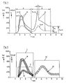
- the shear stress ⁇ reaches maximum values along the mold wall.
- the measuring surface 9 is shown as an example of a plane surface perpendicular to the sensor axis. However, it can also consist of more than one surface or be non-plan.
- the solidification shear stress ⁇ y is orthogonal to ⁇ x. From these two values, the size of the max. Shear stress vector ⁇ max. and the directional angle ⁇ can be determined.
- the specialist can find the critical measuring point or points where the sensor is to be attached. At the same time, the specialist also recognizes the direction in which the most dangerous solidification voltages act. In most cases, especially for production monitoring, he will therefore only check a single shear stress axis, eg ⁇ x, in order to be able to assess the influence of various process parameters.
- Fig. 4 shows an example of such an investigation with e.g. two different materials M and N.
- 15 are the compressive stress curves of different materials pz M and pz N, which are almost similar.
- the differences in the shear stress curves 16 in the solidification phase B are quite astonishing, so that the two materials have considerable residual stress differences ⁇ x. This shows that the significance of the shear stresses with regard to quality requirements opens up a new dimension.
- the "fall" K of the shear stress curve ⁇ x M is of interesting significance.
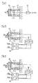
- Fig. 6 shows a sensor corresponding to Fig. 2 in section.
- the sensor can be installed directly in the molded part 2 or via the sleeve 6, which is part of the sensor 7.
- the clearance S can be provided with the sealing ring 22 in certain cases.
- the transfer stamp 25 conducts the measuring forces received by the sensor head 5 to the crystal pair 23, which is poled with the same name, i.e. Both crystal pieces 23 result in a load of the same name on the inside in the Z direction, e.g. negative charge.
- the electrodes 24 remove the electrical charges from the metallized crystal surfaces and conduct them to the connecting cable 36. (FIG. 12)
- Fig. 7 shows a variant of Fig. 6; the crystal arrangement 23 is accommodated directly in the sensor head 5.
- Fig. 8 shows the floor plan of Fig. 7; the crystal pair 23 is separated by the filler 26 and the electrodes 24 are installed in the filler 26.
- Fig. 9 shows the measuring and switching arrangement when the sensor should measure only one component, the shear stress ⁇ x, which results in the simplest switching.
- the electrodes 24 can be interconnected, the signals of which are fed to a charge amplifier 30, which directly outputs an output voltage U.
- the prerequisite for this simplification is a pair of crystals 23 (+) (-) with the same polarity.
- FIG. 10 shows the same arrangement with two crystal pairs 23 with the same polarity of the same name for two components pz and ⁇ x.
- the electronic outlay on charge amplifiers 30, summing devices 31 and differential devices 32 is the same in the two cases.
- FIG. 12 shows the electronic circuit of the arrangement according to the invention more clearly.
- the simpler two-component case is shown with the crystal pair 23 of the same name, installed e.g. in the sensor according to Fig. 6,7.
- the two-wire, externally shielded connecting cable 36 leads to the amplifier box 33, in which the two charge amplifiers 30, the summing device 31 and the differential device 32 are accommodated.
- the two signals are at the output pz and ⁇ x as well as the "Operate" connection for switching on the devices. Thanks to the latest hybrid technology, all four sub-units have small dimensions and are reliable and inexpensive thanks to Solidstate technology.
- the method according to the invention and the device according to the invention for detecting material stresses will open up new possibilities mainly in injection molding technology with plastics, metals and ceramics.
- piezoelectric crystal sensors can be built that can withstand peak temperatures of up to + 500 ° C.
- piezoresistive basis Similar individual elements are also possible on a piezoresistive basis with diffused silicon elements. However, thin-film or strain gage-equipped measuring elements can also be used. Because of the simple signal acquisition, however, piezoelectric arrangements are best because they are also the most reliable.
Landscapes
- Physics & Mathematics (AREA)
- General Physics & Mathematics (AREA)
- Engineering & Computer Science (AREA)
- Manufacturing & Machinery (AREA)
- Mechanical Engineering (AREA)
- Injection Moulding Of Plastics Or The Like (AREA)
- Force Measurement Appropriate To Specific Purposes (AREA)
- Investigating Strength Of Materials By Application Of Mechanical Stress (AREA)
- Compositions Of Oxide Ceramics (AREA)
Applications Claiming Priority (2)
| Application Number | Priority Date | Filing Date | Title |
|---|---|---|---|
| CH3291/92 | 1992-10-23 | ||
| CH3291/92A CH685613A5 (de) | 1992-10-23 | 1992-10-23 | Verfahren und Vorrichtung zum Erfassen von Materialspannungen in Formteilen. |
Publications (3)
| Publication Number | Publication Date |
|---|---|
| EP0594533A2 true EP0594533A2 (fr) | 1994-04-27 |
| EP0594533A3 EP0594533A3 (fr) | 1995-02-15 |
| EP0594533B1 EP0594533B1 (fr) | 1996-12-27 |
Family
ID=4252808
Family Applications (1)
| Application Number | Title | Priority Date | Filing Date |
|---|---|---|---|
| EP93810688A Expired - Lifetime EP0594533B1 (fr) | 1992-10-23 | 1993-09-29 | Méthode et dispositif de détection des tensions de matériaux dans les pièces préformées |
Country Status (6)
| Country | Link |
|---|---|
| US (1) | US5427516A (fr) |
| EP (1) | EP0594533B1 (fr) |
| JP (1) | JPH06221935A (fr) |
| AT (1) | ATE146875T1 (fr) |
| CH (1) | CH685613A5 (fr) |
| DE (1) | DE59304883D1 (fr) |
Families Citing this family (16)
| Publication number | Priority date | Publication date | Assignee | Title |
|---|---|---|---|---|
| CA2164302A1 (fr) * | 1993-10-18 | 1995-04-27 | Jean-Pierre Ibar | Procede et dispositif de moulage par injection |
| JP3501486B2 (ja) * | 1993-12-27 | 2004-03-02 | キヤノン株式会社 | 射出成形品の変形量予測方法及びその装置 |
| CH692891A5 (de) * | 1997-10-13 | 2002-11-29 | Kk Holding Ag | Kabel-Montageanordnung für piezoelektrische Piezo-Aufnehmer. |
| US6294113B1 (en) * | 1998-11-16 | 2001-09-25 | General Electric Company | Touch sensing method |
| US6397677B1 (en) | 2000-06-06 | 2002-06-04 | Kistler Instrument Corporation | Piezoelectric rotational accelerometer |
| GB2364127B (en) * | 2000-06-29 | 2004-08-25 | Univ London | Method and apparatus for monitoring structural fatigue and use |
| DE10238721A1 (de) * | 2002-08-23 | 2004-03-11 | Robert Bosch Gmbh | Vorrichtung zur Messung einer Kraft, Vorrichtung zur Messung eines Drucks und Drucksensor |
| DE10359975A1 (de) * | 2003-12-18 | 2005-07-14 | Priamus System Technologies Ag | Verfahren zum Betreiben einer Arbeitsgerätschaft |
| DE102005054193B4 (de) * | 2005-11-14 | 2009-08-13 | Rodenstock Gmbh | Spannungsmessung von Beschichtungen mit einem Piezoaktuator |
| US8753553B2 (en) * | 2008-04-14 | 2014-06-17 | University Of Massachusetts | Methods for forming injected molded parts and in-mold sensors therefor |
| WO2011042153A1 (fr) * | 2009-10-05 | 2011-04-14 | Priamus System Technologies Ag | Procédé pour réguler la fabrication d'un produit |
| DE102011051200A1 (de) * | 2011-06-20 | 2012-12-20 | Priamus System Technologies Ag | Sensor |
| JP5636145B2 (ja) * | 2012-12-27 | 2014-12-03 | 双葉電子工業株式会社 | 射出成形金型用導光体付ピン |
| WO2016100314A2 (fr) * | 2014-12-19 | 2016-06-23 | The Procter & Gamble Company | Procédé et appareil pour surmoulage d'article creux fragile |
| EP3470809B1 (fr) * | 2017-10-16 | 2020-07-15 | Kistler Holding AG | Capteur de pression pour un outil de traitement des métaux ou des matières plastiques |
| CN116020983B (zh) * | 2022-12-08 | 2023-08-18 | 中国原子能科学研究院 | 用于中子残余应力谱仪的凝固特征模拟装置 |
Family Cites Families (18)
| Publication number | Priority date | Publication date | Assignee | Title |
|---|---|---|---|---|
| US3767339A (en) * | 1971-11-01 | 1973-10-23 | Hunkar Instr Dev Labor Inc | Injection molding control |
| US3893792A (en) * | 1973-04-06 | 1975-07-08 | Bbf Group Inc | Controller for injection molding machine |
| US3840312A (en) * | 1973-04-11 | 1974-10-08 | Control Process Inc | Dynamic pressure control system |
| US4208176A (en) * | 1975-06-16 | 1980-06-17 | Litton Industrial Products, Inc. | Time independent cycle control for plastic injection molding machines |
| US4100598A (en) * | 1975-09-05 | 1978-07-11 | Hoffmann-La Roche Inc. | Tablet press related instrumentation for use in development and control of formulations of pharmaceutical granulations |
| DE2855746C3 (de) * | 1978-12-22 | 1981-07-30 | Kistler Instrumente Ag, Winterthur | Piezoelektrischer Dehnungsaufnehmer |
| US4240996A (en) * | 1979-04-09 | 1980-12-23 | Hunkar Laboratories, Inc. | Process for controlling part density in fast injection molding machines |
| JPS5627622A (en) * | 1979-08-15 | 1981-03-18 | Toyota Motor Corp | Sensor |
| JPS56146741A (en) * | 1980-04-18 | 1981-11-14 | Hitachi Ltd | Setting of holding time and system therefor |
| JPS5723831A (en) * | 1980-07-19 | 1982-02-08 | Yamatake Honeywell Co Ltd | Assembling body combined with brittle material tube |
| US4735760A (en) * | 1985-01-24 | 1988-04-05 | Toshiba Kikai Kabushiki Kaisha | Method and apparatus for controlling injection step of injection molding machines |
| US4651120A (en) * | 1985-09-09 | 1987-03-17 | Honeywell Inc. | Piezoresistive pressure sensor |
| JPS62144916A (ja) * | 1985-12-19 | 1987-06-29 | Matsushita Electric Ind Co Ltd | 樹脂成形モニタリング方法およびその装置 |
| EP0266452A1 (fr) * | 1986-11-07 | 1988-05-11 | Kristal Instrumente AG | Capteur piézoélectrique |
| EP0279081B1 (fr) * | 1987-02-16 | 1992-09-30 | Consiglio Nazionale Delle Ricerche | Dispositif et procédé de contrôle de la réticulation des élastomères dans un moule |
| JPS6432134A (en) * | 1987-07-29 | 1989-02-02 | Kawasaki Steel Co | Residual stress measuring method for coating material |
| DE4129701C2 (de) * | 1991-09-06 | 1994-07-28 | Halil Ulusar Dr Akbay | Meßverfahren zur Messung von mechanischen Spannungen und Meßwertaufnehmer zur Durchführung des Verfahrens |
| US5249163A (en) * | 1992-06-08 | 1993-09-28 | Erickson Jon W | Optical lever for acoustic and ultrasound sensor |
-
1992
- 1992-10-23 CH CH3291/92A patent/CH685613A5/de not_active IP Right Cessation
-
1993
- 1993-09-29 AT AT93810688T patent/ATE146875T1/de active
- 1993-09-29 EP EP93810688A patent/EP0594533B1/fr not_active Expired - Lifetime
- 1993-09-29 DE DE59304883T patent/DE59304883D1/de not_active Expired - Fee Related
- 1993-10-21 US US08/139,040 patent/US5427516A/en not_active Expired - Fee Related
- 1993-10-22 JP JP5265036A patent/JPH06221935A/ja not_active Withdrawn
Also Published As
| Publication number | Publication date |
|---|---|
| US5427516A (en) | 1995-06-27 |
| JPH06221935A (ja) | 1994-08-12 |
| ATE146875T1 (de) | 1997-01-15 |
| CH685613A5 (de) | 1995-08-31 |
| EP0594533B1 (fr) | 1996-12-27 |
| EP0594533A3 (fr) | 1995-02-15 |
| DE59304883D1 (de) | 1997-02-06 |
Similar Documents
| Publication | Publication Date | Title |
|---|---|---|
| EP0594533B1 (fr) | Méthode et dispositif de détection des tensions de matériaux dans les pièces préformées | |
| EP0886762B1 (fr) | Procede et dispositif pour controler un detecteur | |
| DE69127144T2 (de) | Volumentest einer Plastikflasche in einer Produktionslinie | |
| DE69622483T2 (de) | Verfahren zum Simulieren des Verhalten von Harz beim Druckgiessen | |
| EP0887171A1 (fr) | Procédé pour définir le point de commutation durant la production d'une pièce injectée | |
| DE6940548U (de) | Mehrkomponenten- kraft- und momentenmessanordnung | |
| DE102009053043A1 (de) | Kraftmesszelle zur Messung der Einspritzkraft beim Spritzgießen | |
| EP0459947B1 (fr) | Système de mesure de tension de barre dans par example machines de moulage par injection | |
| DE2758105C2 (de) | Vorrichtung zum Kühlen von rückgeführtem Gießereiformmaterial | |
| DE102007012549A1 (de) | Vorrichtung und Verfahren zur Herstellung von Formkörpern aus feuchtem Beton oder artverwandten Materialien | |
| EP1695057B1 (fr) | Procede d'exploitation d'un arbre d'outil | |
| DE102011083133A1 (de) | Verfahren zur Selbstüberwachung einer keramischen Druckmesszelle eines kapazitiven Drucksensors und eine Auswerteschaltung zur Durchführung des Verfahrens | |
| DE19525142C1 (de) | Verfahren zur Erfassung der an einer Spritzgießmaschine auftretenden Kräfte sowie Vorrichtung zur Durchführung des Verfahrens | |
| DE2117256B2 (de) | Verfahren und Vorrichtung zum Bestimmen von mechanischen Eigen schäften von Bitumengemischen, die bei nach dem Marshall Verfahren durch geführten Versuchen gewonnen werden | |
| DE3736904A1 (de) | Messeinrichtung mit sensorelementen | |
| EP0451172B1 (fr) | Dispositif de commande dans le temps de la pression de remplissage d'outils de moulage par compression | |
| DE69016140T2 (de) | Anordnung für spritzgiessmaschinen zum unterscheiden brauchbarer teile von ausschussstücken. | |
| EP2174768B1 (fr) | Dispositif de détermination des forces survenant sur une machine de moulage par injection | |
| DE10114006A1 (de) | Messvorrichtung | |
| DE102022117755A1 (de) | Sensoreinheit zur Überwachung einer Kavität in einer Spritzgiessform | |
| EP0498759B1 (fr) | Dispositif de mesure pour indiquer simultanément un signal électrique et un signal partiel superpositionné | |
| EP2103410B1 (fr) | Machine de moulage par injection de matière plastique dotée d'un dispositif de mesure de la force d'injection | |
| DE4025353A1 (de) | Keilfoermiges oder konisches kraftmesselement | |
| AT7859U1 (de) | Verfahren zur überwachung der schliesskraft einer spritzgiessmaschine | |
| DE3834439A1 (de) | Klemmstueck fuer messtaster |
Legal Events
| Date | Code | Title | Description |
|---|---|---|---|
| PUAI | Public reference made under article 153(3) epc to a published international application that has entered the european phase |
Free format text: ORIGINAL CODE: 0009012 |
|
| AK | Designated contracting states |
Kind code of ref document: A2 Designated state(s): AT DE FR GB IT |
|
| PUAL | Search report despatched |
Free format text: ORIGINAL CODE: 0009013 |
|
| AK | Designated contracting states |
Kind code of ref document: A3 Designated state(s): AT DE FR GB IT |
|
| 17P | Request for examination filed |
Effective date: 19950627 |
|
| GRAG | Despatch of communication of intention to grant |
Free format text: ORIGINAL CODE: EPIDOS AGRA |
|
| GRAH | Despatch of communication of intention to grant a patent |
Free format text: ORIGINAL CODE: EPIDOS IGRA |
|
| 17Q | First examination report despatched |
Effective date: 19960523 |
|
| GRAH | Despatch of communication of intention to grant a patent |
Free format text: ORIGINAL CODE: EPIDOS IGRA |
|
| GRAA | (expected) grant |
Free format text: ORIGINAL CODE: 0009210 |
|
| AK | Designated contracting states |
Kind code of ref document: B1 Designated state(s): AT DE FR GB IT |
|
| PG25 | Lapsed in a contracting state [announced via postgrant information from national office to epo] |
Ref country code: IT Free format text: LAPSE BECAUSE OF FAILURE TO SUBMIT A TRANSLATION OF THE DESCRIPTION OR TO PAY THE FEE WITHIN THE PRE;WARNING: LAPSES OF ITALIAN PATENTS WITH EFFECTIVE DATE BEFORE 2007 MAY HAVE OCCURRED AT ANY TIME BEFORE 2007. THE CORRECT EFFECTIVE DATE MAY BE DIFFERENT FROM THE ONE RECORDED.SCRIBED TIME-LIMIT Effective date: 19961227 Ref country code: GB Effective date: 19961227 Ref country code: FR Effective date: 19961227 |
|
| REF | Corresponds to: |
Ref document number: 146875 Country of ref document: AT Date of ref document: 19970115 Kind code of ref document: T |
|
| REF | Corresponds to: |
Ref document number: 59304883 Country of ref document: DE Date of ref document: 19970206 |
|
| EN | Fr: translation not filed | ||
| GBV | Gb: ep patent (uk) treated as always having been void in accordance with gb section 77(7)/1977 [no translation filed] |
Effective date: 19961227 |
|
| PG25 | Lapsed in a contracting state [announced via postgrant information from national office to epo] |
Ref country code: AT Free format text: LAPSE BECAUSE OF NON-PAYMENT OF DUE FEES Effective date: 19970929 |
|
| PLBE | No opposition filed within time limit |
Free format text: ORIGINAL CODE: 0009261 |
|
| STAA | Information on the status of an ep patent application or granted ep patent |
Free format text: STATUS: NO OPPOSITION FILED WITHIN TIME LIMIT |
|
| 26N | No opposition filed | ||
| PGFP | Annual fee paid to national office [announced via postgrant information from national office to epo] |
Ref country code: DE Payment date: 20001122 Year of fee payment: 8 |
|
| PG25 | Lapsed in a contracting state [announced via postgrant information from national office to epo] |
Ref country code: DE Free format text: LAPSE BECAUSE OF NON-PAYMENT OF DUE FEES Effective date: 20020501 |