EP0594742B1 - Fernmeldedienstnetz - Google Patents
Fernmeldedienstnetz Download PDFInfo
- Publication number
- EP0594742B1 EP0594742B1 EP92915737A EP92915737A EP0594742B1 EP 0594742 B1 EP0594742 B1 EP 0594742B1 EP 92915737 A EP92915737 A EP 92915737A EP 92915737 A EP92915737 A EP 92915737A EP 0594742 B1 EP0594742 B1 EP 0594742B1
- Authority
- EP
- European Patent Office
- Prior art keywords
- interface
- user
- service
- user terminal
- service bank
- Prior art date
- Legal status (The legal status is an assumption and is not a legal conclusion. Google has not performed a legal analysis and makes no representation as to the accuracy of the status listed.)
- Expired - Lifetime
Links
- 230000000007 visual effect Effects 0.000 claims description 4
- 230000005540 biological transmission Effects 0.000 description 4
- 238000001514 detection method Methods 0.000 description 2
- 230000011664 signaling Effects 0.000 description 2
- 230000006978 adaptation Effects 0.000 description 1
- 239000004020 conductor Substances 0.000 description 1
- 238000010586 diagram Methods 0.000 description 1
- 238000005516 engineering process Methods 0.000 description 1
- 230000002452 interceptive effect Effects 0.000 description 1
- 230000003287 optical effect Effects 0.000 description 1
- 230000002093 peripheral effect Effects 0.000 description 1
- 230000002285 radioactive effect Effects 0.000 description 1
- 229920006395 saturated elastomer Polymers 0.000 description 1
- 230000005236 sound signal Effects 0.000 description 1
Images
Classifications
-
- H—ELECTRICITY
- H04—ELECTRIC COMMUNICATION TECHNIQUE
- H04M—TELEPHONIC COMMUNICATION
- H04M11/00—Telephonic communication systems specially adapted for combination with other electrical systems
- H04M11/08—Telephonic communication systems specially adapted for combination with other electrical systems specially adapted for optional reception of entertainment or informative matter
-
- H—ELECTRICITY
- H04—ELECTRIC COMMUNICATION TECHNIQUE
- H04M—TELEPHONIC COMMUNICATION
- H04M3/00—Automatic or semi-automatic exchanges
- H04M3/42—Systems providing special services or facilities to subscribers
- H04M3/428—Arrangements for placing incoming calls on hold
-
- H—ELECTRICITY
- H04—ELECTRIC COMMUNICATION TECHNIQUE
- H04M—TELEPHONIC COMMUNICATION
- H04M3/00—Automatic or semi-automatic exchanges
- H04M3/42—Systems providing special services or facilities to subscribers
- H04M3/487—Arrangements for providing information services, e.g. recorded voice services or time announcements
- H04M3/493—Interactive information services, e.g. directory enquiries ; Arrangements therefor, e.g. interactive voice response [IVR] systems or voice portals
Definitions
- This invention relates to a telecommunications service network.
- a public telecommunications network may include a plurality of user terminals interconnected with each other by a telephone exchange. Normally each user terminal would be a telephone although it is now common for terminals to comprise tele-typewriters, facsimile apparatus, computer ports or the like.
- the network allows for the transmission of information in digital or analogue form along an electrical cable, optical fibres or even as radio signals.
- the network may also allow for the communication of information representative of audio or video signals.
- the telephone exchange is a local switching office whereby a user terminal can be selectively connected with any other terminal in the network to allow for private communications between users.
- the local switching office may be connected to other switching offices by trunk lines to allow for user transmissions between different telephone exchanges.
- a telephone exchange is designed to have a switching capacity less than the number of user terminals for reasons of economy but to provide such capacity as to offer subscribers an acceptable degree of line availability.
- various services such as weather forecast, speaking clock, local radio, or interactive services such as banking, allow a terminal user to dial and obtain some information as and when it is desired.
- the user first lifts the telephone handset and the telephone terminal signals to the local exchange, usually by drawing a DC current.
- the user dials the service number by pulse dialling or audio frequency signalling.
- the call is then connected by the exchange to the requested service.
- the user may interact with the service selected.
- the service may be responsive to voice or word recognition.
- the user will be taking up switching capacity in the telephone exchange for the duration of the call. The user would, therefore, be discouraged from, say, listening to a radio station over the telephone (if this service were to be available from a service provider) for a long period of time because of the expense of the call.
- broadcast media in the case of local radio, the commonality of interest is set only by the listeners' co-location in the same town or district, whereas individuals' interests are more often defined by other factors, such as career, pastimes and lifestyle.
- provision of services to such groups can conveniently be expressed by the term "narrowcasting" which contrasts with the general concept of broadcasting that, by its very nature, cannot address individuals' requirements for information or entertainment services at times that are convenient to the individual rather than to the network.
- One way to meet such individuals' requirements for a multiplicity of services is to use the telephone network. If a greater variety of services were on offer, particularly if such services catered for minority interests not well served by other broadcasting media, users would be encouraged to make greater use of dial-up service systems. In a standard telecommunications network, if the number of services offered to users is particularly large, or if a service becomes very popular at a specific time, then the telephone exchange may become overloaded and run out of switching capacity. Services by their very nature should be exploitable by more than one user. This contrasts with person to person private telephone calls which generally are between just two users at any one time. It does not, therefore, represent efficient use for a service system to be placed in the telecommunications network in a manner equivalent to an ordinary user terminal.
- US Patent US-A-3 106 611 discloses a special service telephone concentrator for hotels or the like in which an interface unit switches between telephone calls from the hotel switchboard and selected audio services.
- Each telephone terminal is provided with a selector switch, such as a wafer switch, which selects the required audio service by means of an additional conductor connected to the interface unit.
- an interface for a telecommunications service network the interface being connectable between a telecommunications switching exchange and a plurality of fixed or mobile user terminals, the interface also being connectable to a service bank for transmitting selected ones of a plurality of services, the interface including switching means provided between the switching exchange, the service bank and each of at least some of the user terminals, wherein selective setting of each of the switching means provides connection between the respective user terminal and either the switching exchange or the service bank, the interface being responsive to an operation of one of the user terminals to set the respective switching means to select connection between the user terminal and the service bank, each switching means including sensing means for sensing an attempted incoming call to the respective user terminal when selectively connected to the service bank, characterised in that the interface is capable of use with standard telephone user terminals in a public telecommunications system by virtue of the switching means in the interface being responsive to standard operational signals from the user terminals.
- a telephone user can communicate with the terminals of other telephone users in a known manner via the switching exchange.
- the user wishes to access the service bank by telephone and select a service, then this can be achieved without using any of the switching capacity of the switching exchange.
- the user first lifts the handset of the telephone to enter the telecommunications system.
- the telephone is directly connected by, for example, telephone cable, to the telephone exchange via the user interface. Once the telephone handset has been raised by the user, the telephone draws current from the exchange and awaits a user operation.
- the sensing means in the user interface detects the signal and connects the user's terminal directly to the service bank, by-passing the telephone exchange.
- the user interface is located in, or close to, the telephone exchange and the service bank is itself in, or close to, the telephone exchange so as to economise on cabling linking the interface to the service bank.
- a user may have access to the service bank for long periods of time without taking up any of the switching capacity of the telephone exchange. Accordingly, it is possible for a different charging system to apply for calls to the service bank via the user interface.
- the sensing means in the user interface is capable of also sensing an attempted incoming call from the exchange when the user is connected to the service bank. The sensing means can then respond in a number of different ways.
- the sensing means can provide a call breakthrough facility so as to switch the user's terminal automatically back into the main public telecommunications system (that is, provide a connection to the switching exchange) so that the terminal can receive the incoming call.
- the sensing means can provide a call indication facility whereby the user is made aware of an attempted incoming call by, for example, a visual indicator such as a light on the terminal or an audible indication such as a tone; the user can then choose whether or not to receive the incoming call by terminating the connection to the service bank by replacing the terminal handset.
- Suitable means such as a switch can be provided on the terminal to allow the user to select between these different modes of operation of the sensing means.
- the sensing means could be inhibited by the switch to prevent interruption when the user wishes to have continuous connection to a programme or the like provided by the service bank without receiving incoming calls.
- the terminal it may be desired for the terminal to have the ability for the user to dial out even when a service is being received from the service bank.
- a user terminal could selectively have access to a whole range of services in the service bank. Whilst accessing the service bank, the user does not take up any of the switching capacity of the exchange. It is therefore impossible for the switching exchange to be saturated due to insufficient switching capacity on the basis of calls to the service bank. Since each user terminal has its own user interface with the service bank, it is always able to gain access to the service bank provided that the user knows the particular signal required to be transmitted down the line to the sensing means in the user interface in order to access the service bank.
- the quality of transmissions from the service bank is not dictated by the public telecommunications system as a whole and hence it is possible for services within the bank to be of a high audio or visual quality according to demand.
- Digital technology allows for the transmission of, for instance, audio signals that are of hi-fi quality.
- the ISDN standard even allows for high quality stereo signals to be transmitted, with or without still or moving video picture data.
- the user's telephone terminal it would be possible for the user's telephone terminal to itself have a subscriber ISDN interface connecting the service network to both the telephone and the user's personal hi-fi system. The user may then be able to listen on the hi-fi system to high quality music or radio broadcasts that have been transmitted from the service bank.
- the service facilities may be received on a standard two-wire telephone, the facilities may be enhanced by the use of further equipment.
- the sensing means in the user interface includes a timer activated by lifting of the handset by the user. Should the user not dial a number within a predetermined time, then the sensing means causes automatic actuation of the switch in the user interface and connects the user's terminal with the service bank in the service network. This can provide an alternative means of connection to the service bank other than dialling a specific code for this purpose or sending a characteristic signal by some other means.
- the provision of the timer allows other facilities to be made available. For example, if the user wishes to be woken by a selected audio service available from the service bank such as a radio station, the user would set the predetermined time to the desired alarm time.
- the radio station When the alarm time is reached, the radio station is automatically transmitted from the service bank to the user terminal via the switch in the user interface. If, in the meantime, another user is attempting to call the user's terminal, then the sensing means would sense this and respond accordingly, such as by call breakthrough or actuation of the indicator means.
- a service bank may include a series of audio services such as selectable music titles.
- a user may be able to compose any desired medley of music titles without having to rely on a radio station.
- the service bank thereby acts as a music library within easy access of a user.
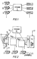
- a telephone switching exchange 1 is shown connected to various user telephone terminals V , W , X , Vietnamese and to service terminals v , w , x , Vietnamese
- a user of, for instance, the terminal V can access any one of the services provided by the service terminals v , w , x , by dialling an appropriate telephone number.
- the user could dial any one of the other terminals W , X , . No distinction is made between the service terminals v , w , x Vietnamese and the user terminals V , W , X and hence the user must always pass through the switching exchange 1 in order to communicate with a service.
- FIG. 2 there is shown a schematic representation of a telecommunications service network embodying the invention and incorporated in a public telecommunications system.
- a plurality of user telephone terminals A , B , C , Vietnamese are interconnected by an exchange 10.
- Each user terminal A , B , C is respectively connected to a user interface a , b , c , Vietnamese
- the user interface a is shown in detail.
- the terminal A is connected to the interface a by a cable 11.
- the interface a is connected to the exchange 10 by a cable 12.
- the cable 11 is normally connected to the cable 12 by a switch 13 so that the terminal A is fully connectable to the network of terminals B , C , Vietnamese by the exchange 10.
- the switch 13 may or may not be a physical switch, and may be connected to associated circuitry providing the necessary network conditions.
- a service cable 14 a connects the interface a to a service bank 15 via a multiplexer/distributor 16.
- the multiplexer/distributor 16 allows access to a selected service within the service bank 15 by the service cable 14 a for the interface a , by a service cable 14 b for the interface b , by a service cable 14 c for the interface c , and so on.
- a detector 17 in the interface a picks up signals from the cable 11 and a controller 18 senses these signals. If the user of the terminal A sends a signal down the cable 11 from a telephone at the terminal A that is representative of an access code for the service bank 15, then the controller 18 senses the signal via the detector 17 and causes the switch 13 to connect the terminal A to the multiplexer/distributor 16. The user of the terminal A can now communicate with the service bank 15 in a known manner.
- the detector 17 also senses signals on the cable 12, such as those representative of an attempted incoming call from another user, for example, a user of a telephone at the terminal B . The manner of treatment of such an attempted incoming call depends on the mode of operation of the system.
- the controller 18 provides a call breakthrough facility which switches the user's terminal back into communication with the exchange 10. In such a case, the controller 18 will respond to detection of the incoming call by the detector 17 and will cause the switch 13 to connect the terminal A to the exchange 10. As a result, the user of the terminal B will be able to interrupt the service and communicate directly with the user of the terminal A .
- the controller 18 can provide an indication of an attempted incoming call from another user. In this case, in response to detection of an attempted incoming call by the detector 17, the controller 18 will cause an alert signal to be generated by an alert generator 20 and passed to the terminal A along the line 11.
- the alert signal may provide an audible indication so that the user of the terminal A will be aware of the attempted incoming call; alternatively, the alert signal may cause a visual indicator such as a light (not shown) to show on the terminal A .
- the user may then respond accordingly, either by ignoring the call indication or by terminating the connection to the service bank 15 and receiving the incoming call.
- the controller 18 may be set so as to prevent interruption of a programme or similar provided by the service bank 15. In that case, the switch 13 will remain connected to the service cable 14 a and the controller 18 will generate an engaged tone by means of a tone generator 19 connected to the line 12 so as to notify the user of the terminal B that the terminal A is in use.
- a selection switch or key (not shown) can be provided at the terminals A , B , C , ... so as to allow the user to select between the above modes of operation of the controller 18. Operation of the selection switch would then send signals along the cable 11 which would be detected by the detector 17 and the controller 18 would be set accordingly.
- the service bank 15 is shown in Figure 2 as receiving an external input via a terminal 21. This allows the service bank 15 to have access to external services, such as local radio stations from other regions which may not be readily receivable by radios in the particular region. This would make it possible for an extended variety of services to be provided, not limited by the storage capacity of the service bank 15.
- the service facilities may be enhanced by the addition of further equipment.
- the telephone at the terminal C is shown as having a connection to a stereo system 22 such that, with a suitable digital system such as one complying with the ISDN standard, high quality stereo audio may be received and amplified by the stereo system 22.
- the terminals could be made capable of receiving still or moving video picture data. In that case, connection to a display device such as a television or monitor screen would be necessary.
- the telephone at the terminal C is shown as having a connection to the stereo system 22 and such a telephone would require special adaptation for this purpose.
- an interface could be provided between the telephone and the cable 11, the terminal then being a standard telephone with all peripheral connections (such as to the stereo system and/or the display screen) being made to the interface.
- Telecommunications service networks as described above are extremely versatile and, once incorporated into public telecommunications systems, allow for a wide variety of user services.
Landscapes
- Engineering & Computer Science (AREA)
- Signal Processing (AREA)
- Telephonic Communication Services (AREA)
- Mobile Radio Communication Systems (AREA)
Claims (8)
- Interface für ein Netzwerk von Telekommunikationsdienstleistungen, wobei das Interface (a; b; c) zwischen einem Umschaltaustauscher für Telekommunikation und eine Mehrzahl von festen oder beweglichen Benutzerterminals (A; B; C) angeschlossen werden kann, wobei das Interface (a; b; c) auch mit einer Bank bzw. Bibliothek (15) von Dienstleistungen verbindbar ist, um aus einer Mehrzahl von Dienstleistungen ausgewählte zu übertragen, wobei das Interface (a; b; c) Schalteinrichtungen (13) aufweist, die zwischen dem Umschaltaustauscher (10), der Dienstleistungsbibliothek (15) und jedem von zumindest einigen der Benutzerterminals (A; B; C) vorgesehen sind, wobei das gezielte Einstellen jeder der Umschalteinrichtungen (13) die Verbindung zwischen dem betreffenden Benutzerterminal (A; B; C) und entweder dem Umschaltaustauscher (10) oder der Dienstleistungsbibliothek (15) bereitstellt, das Interface (a; b; c) auf den Betrieb an einem der Benutzerterminals (A; B; C) anspricht, um die jeweiligen Umschalteinrichtungen (13) so einzustellen, daß sie die Verbindung zwischen dem Benutzerterminal (A; B; C) und der Dienstleistungsbibliothek (15) auswählen, wobei jede Schalteinrichtung (13) eine Abfühleinrichtung (18) aufweist, um den Versuch einer eingehenden Anfrage an das jeweilige Benutzerterminal (A; B; C) abzufühlen, wenn dieses gezielt mit der Dienstleistungsbibliothek (15) verbunden ist, dadurch gekennzeichnet, daß das Interface (a; b; c) in der Lage ist, mit standardmäßigen Telefonbenutzeranschlüssen (A; B; C) in einem öffentlichen Telekommunikationssystem benutzt zu werden, indem die Umschalteinrichtung (13) in dem Interface (a; b; c) auf standardmäßige Betriebssignale von den Benutzerterminals (A; B; C) anspricht.
- Interface nach Anspruch 1, wobei der Einstellvorgang des Benutzerterminals (A; B; C) das Wählen eines vorbestimmten Codes aufweist.
- Interface nach Anspruch 1, wobei der Einstellvorgang des Benutzerterminals (A; B; C) das Anheben eines Hörers bzw. in der Hand zu haltenden Teiles des Benutzerterminals aufweist, wobei ein Signal von dem Benutzerterminal (A; B; C) zu dem Interface (a; b; c) geschickt wird, welches dann so anspricht, daß es die Verbindung zu der Dienstleistungsbibliothek (15) auswählt, wenn das Signal länger als eine vorbestimmte Zeit aufrechterhalten wird.
- Interface nach Anspruch 1, 2 oder 3, wobei jede Umschalteinrichtung (13) auf das Erfühlen des Versuchs einer eingehenden Anfrage anspricht, um die Verbindung des betreffenden Benutzerterminals (A; B; C) von der Dienstleistungsbibliothek (15) zu dem Umschaltaustauscher (10) zu ändern.
- Interface nach einem der vorstehenden Ansprüche, wobei jede Umschalteinrichtung (13) auf den abgefühlten Versuch einer eingehenden Anfrage anspricht, um an dem betreffenden Benutzerterminal (A; B; C) eine Anzeige bereitzustellen.
- Interface nach Anspruch 5, wobei die Anzeige eine hörbare Anzeige ist.
- Interface nach Anspruch 5, wobei die Anzeige eine sichtbare Anzeige ist.
- Interface nach einem der vorstehenden Ansprüche, wobei die Dienstleistungsbibliothek (15) Einrichtungen (21) für das Empfangen externer Daten aufweist.
Applications Claiming Priority (3)
| Application Number | Priority Date | Filing Date | Title |
|---|---|---|---|
| GB91155200 | 1991-07-18 | ||
| GB9115520A GB2257870B (en) | 1991-07-18 | 1991-07-18 | Telecommunications service network |
| PCT/GB1992/001332 WO1993002521A1 (en) | 1991-07-18 | 1992-07-20 | Telecommunications service network |
Publications (2)
| Publication Number | Publication Date |
|---|---|
| EP0594742A1 EP0594742A1 (de) | 1994-05-04 |
| EP0594742B1 true EP0594742B1 (de) | 1998-09-23 |
Family
ID=10698554
Family Applications (1)
| Application Number | Title | Priority Date | Filing Date |
|---|---|---|---|
| EP92915737A Expired - Lifetime EP0594742B1 (de) | 1991-07-18 | 1992-07-20 | Fernmeldedienstnetz |
Country Status (4)
| Country | Link |
|---|---|
| EP (1) | EP0594742B1 (de) |
| DE (1) | DE69227111T2 (de) |
| GB (1) | GB2257870B (de) |
| WO (1) | WO1993002521A1 (de) |
Families Citing this family (3)
| Publication number | Priority date | Publication date | Assignee | Title |
|---|---|---|---|---|
| US5341415A (en) * | 1992-09-22 | 1994-08-23 | Paul Baran | Method and apparatus for sharing of common in-house wiring to permit multiple telephone carriers to serve the same customer |
| US5488569A (en) * | 1993-12-20 | 1996-01-30 | At&T Corp. | Application-oriented telecommunication system interface |
| NL9401122A (nl) * | 1994-07-05 | 1996-02-01 | Nederland Ptt | Systeem voor de distributie van signalen. |
Family Cites Families (5)
| Publication number | Priority date | Publication date | Assignee | Title |
|---|---|---|---|---|
| US3106611A (en) * | 1960-08-24 | 1963-10-08 | Automatic Elect Lab | Special service concentrator system |
| GB1235966A (en) * | 1968-05-21 | 1971-06-16 | Int Standard Electric Corp | Circuit arrangement for telephone exchanges to enable an existing call to be temporarily interrupted |
| US4577067A (en) * | 1983-10-05 | 1986-03-18 | Alfred Levy | Remotely controlled telephone hold program system |
| DE3407216A1 (de) * | 1984-02-28 | 1985-08-29 | Siemens AG, 1000 Berlin und 8000 München | Verfahren fuer eine fernsprechanlage, insbesondere fernsprechnebenstellenanlage, mit zuordnung besonderer bedienfunktion zu endstellen |
| US4748657A (en) * | 1986-05-22 | 1988-05-31 | Willard Rudd | Handset actuated signal intercept |
-
1991
- 1991-07-18 GB GB9115520A patent/GB2257870B/en not_active Expired - Fee Related
-
1992
- 1992-07-20 EP EP92915737A patent/EP0594742B1/de not_active Expired - Lifetime
- 1992-07-20 WO PCT/GB1992/001332 patent/WO1993002521A1/en not_active Ceased
- 1992-07-20 DE DE69227111T patent/DE69227111T2/de not_active Expired - Fee Related
Also Published As
| Publication number | Publication date |
|---|---|
| GB2257870A (en) | 1993-01-20 |
| WO1993002521A1 (en) | 1993-02-04 |
| EP0594742A1 (de) | 1994-05-04 |
| DE69227111D1 (de) | 1998-10-29 |
| GB2257870B (en) | 1995-06-14 |
| DE69227111T2 (de) | 1999-02-18 |
| GB9115520D0 (en) | 1991-09-04 |
Similar Documents
| Publication | Publication Date | Title |
|---|---|---|
| CA2165704C (en) | Telephone message center | |
| US5550900A (en) | Apparatus and method for routing messages in a telephone message center | |
| CA2165705C (en) | An interactive system for communications between a cordless telephone and a remotely operated device | |
| US6404761B1 (en) | Communications webs with personal communications links for PSTN subscribers | |
| US4776006A (en) | Multiplexed data channel controlled telephone system | |
| US4811382A (en) | Method and apparatus for applying messages in a telecommunications network | |
| CA1279415C (en) | Telephone line carrier system | |
| US8005195B2 (en) | Telephone network messaging | |
| US4013840A (en) | Tdm and fdm telephone communication | |
| WO1989003626A1 (en) | Voice/data switch | |
| TW339491B (en) | Telecommunications system for accessing subscriber premises equipment using ring suppression | |
| US6088440A (en) | Method and apparatus for operating a telephone exchange having selectable audio sources | |
| GB2166622A (en) | Cordless telephone system | |
| JPH08275140A (ja) | 双方向番組の放送方法、双方向番組に対する応答方法および応答装置 | |
| GB2257870A (en) | Telecommunications service network | |
| GB2298552A (en) | Cordless radio telephone system with a plurality of portable units | |
| US20050099984A1 (en) | Broadcast signal delivery system for use with wireless technology | |
| JP3444331B2 (ja) | 発呼者情報通知システム | |
| US20010033566A1 (en) | Methods and apparatus for providing telephonic communication services | |
| KR19980054679A (ko) | 교환기를 이용한 구내방송장치 | |
| JP2985397B2 (ja) | 発呼加入者番号検出方式 | |
| JP2831701B2 (ja) | 片方向情報伝達通信システム | |
| GB2100957A (en) | Call diverter | |
| EP0340231A1 (de) | Fernmeldesysteme | |
| JPH0495453A (ja) | ハウス管理システム |
Legal Events
| Date | Code | Title | Description |
|---|---|---|---|
| PUAI | Public reference made under article 153(3) epc to a published international application that has entered the european phase |
Free format text: ORIGINAL CODE: 0009012 |
|
| 17P | Request for examination filed |
Effective date: 19940215 |
|
| AK | Designated contracting states |
Kind code of ref document: A1 Designated state(s): DE ES FR IT |
|
| 17Q | First examination report despatched |
Effective date: 19961030 |
|
| RAP1 | Party data changed (applicant data changed or rights of an application transferred) |
Owner name: TELSIS HOLDINGS LIMITED |
|
| RIN1 | Information on inventor provided before grant (corrected) |
Inventor name: WILSON, JEFFREY |
|
| GRAG | Despatch of communication of intention to grant |
Free format text: ORIGINAL CODE: EPIDOS AGRA |
|
| GRAG | Despatch of communication of intention to grant |
Free format text: ORIGINAL CODE: EPIDOS AGRA |
|
| GRAH | Despatch of communication of intention to grant a patent |
Free format text: ORIGINAL CODE: EPIDOS IGRA |
|
| GRAH | Despatch of communication of intention to grant a patent |
Free format text: ORIGINAL CODE: EPIDOS IGRA |
|
| GRAA | (expected) grant |
Free format text: ORIGINAL CODE: 0009210 |
|
| AK | Designated contracting states |
Kind code of ref document: B1 Designated state(s): DE ES FR IT |
|
| PG25 | Lapsed in a contracting state [announced via postgrant information from national office to epo] |
Ref country code: IT Free format text: LAPSE BECAUSE OF FAILURE TO SUBMIT A TRANSLATION OF THE DESCRIPTION OR TO PAY THE FEE WITHIN THE PRE;WARNING: LAPSES OF ITALIAN PATENTS WITH EFFECTIVE DATE BEFORE 2007 MAY HAVE OCCURRED AT ANY TIME BEFORE 2007. THE CORRECT EFFECTIVE DATE MAY BE DIFFERENT FROM THE ONE RECORDED.SCRIBED TIME-LIMIT Effective date: 19980923 Ref country code: ES Free format text: THE PATENT HAS BEEN ANNULLED BY A DECISION OF A NATIONAL AUTHORITY Effective date: 19980923 |
|
| REF | Corresponds to: |
Ref document number: 69227111 Country of ref document: DE Date of ref document: 19981029 |
|
| ET | Fr: translation filed | ||
| PLBE | No opposition filed within time limit |
Free format text: ORIGINAL CODE: 0009261 |
|
| STAA | Information on the status of an ep patent application or granted ep patent |
Free format text: STATUS: NO OPPOSITION FILED WITHIN TIME LIMIT |
|
| 26N | No opposition filed | ||
| PGFP | Annual fee paid to national office [announced via postgrant information from national office to epo] |
Ref country code: DE Payment date: 20080920 Year of fee payment: 17 |
|
| PGFP | Annual fee paid to national office [announced via postgrant information from national office to epo] |
Ref country code: FR Payment date: 20080704 Year of fee payment: 17 |
|
| REG | Reference to a national code |
Ref country code: FR Ref legal event code: ST Effective date: 20100331 |
|
| PG25 | Lapsed in a contracting state [announced via postgrant information from national office to epo] |
Ref country code: FR Free format text: LAPSE BECAUSE OF NON-PAYMENT OF DUE FEES Effective date: 20090731 |
|
| PG25 | Lapsed in a contracting state [announced via postgrant information from national office to epo] |
Ref country code: DE Free format text: LAPSE BECAUSE OF NON-PAYMENT OF DUE FEES Effective date: 20100202 |