EP0594846A1 - Procede pour determiner la charge d'une machine pour le moulage a injection - Google Patents
Procede pour determiner la charge d'une machine pour le moulage a injection Download PDFInfo
- Publication number
- EP0594846A1 EP0594846A1 EP91906252A EP91906252A EP0594846A1 EP 0594846 A1 EP0594846 A1 EP 0594846A1 EP 91906252 A EP91906252 A EP 91906252A EP 91906252 A EP91906252 A EP 91906252A EP 0594846 A1 EP0594846 A1 EP 0594846A1
- Authority
- EP
- European Patent Office
- Prior art keywords
- screw
- resin
- pressure
- value
- synthetic resin
- Prior art date
- Legal status (The legal status is an assumption and is not a legal conclusion. Google has not performed a legal analysis and makes no representation as to the accuracy of the status listed.)
- Withdrawn
Links
Images

Classifications
-
- B—PERFORMING OPERATIONS; TRANSPORTING
- B29—WORKING OF PLASTICS; WORKING OF SUBSTANCES IN A PLASTIC STATE IN GENERAL
- B29C—SHAPING OR JOINING OF PLASTICS; SHAPING OF MATERIAL IN A PLASTIC STATE, NOT OTHERWISE PROVIDED FOR; AFTER-TREATMENT OF THE SHAPED PRODUCTS, e.g. REPAIRING
- B29C45/00—Injection moulding, i.e. forcing the required volume of moulding material through a nozzle into a closed mould; Apparatus therefor
- B29C45/17—Component parts, details or accessories; Auxiliary operations
- B29C45/76—Measuring, controlling or regulating
Definitions
- the present invention relates to a method of detecting the weight of plasticized synthetic resin injected from the cylinder of an injection molder to fill in the cavity of a mold.
- the pressure of plasticized synthetic resin in the injection molder cylinder is not controlled nor monitored until immediately before resin injection through the nozzle of the molder. Therefore, the pressure of the plasticized synthetic resin does not become constant in the case of the plasticized synthetiac resin having compressibility. Particularly where the screw of the injection molder is retreated forcedly for reducing the resin pressure in the cylinder so as to prevent the resin from leaking through the injection molder nozzle, the resin pressure fluctuates due to air drawn through the nozzle end.
- the check valve provided at the front end of the screw is open before injection because no pressure is applied to the screw.
- the check valve is closed under pressure applied to the screw for injection, small amount of resin flows back in the cylinder. This also results in the poor detection accuracy of this method.
- the dwelling pressure is varied to meet various molding conditions for different products.
- the compression amount of compressible plasticized synthetic resin varies depending on the dwelling pressure.
- a high detection accuracy could be achieved by comparing the resin amount in the injection molder cylinder under a constant dwelling pressure.
- the dwelling pressure is one of the essential molding conditions that determine the shape and dimensions of moldings, it is impracticable to maintain a constant dwelling pressure.
- the difference in the screw position indicates the volume of injected resin.
- the resin volume changes with the resin temperature and/or the pressure applied to the screw, and is not proportional to the weight of the injected resin.
- the resin temperature and the pressure applied to the screw are among variable molding conditions. So, the difference in the screw position is not a good measure for the weight of injected resin.
- in continuous molding since the hydraulic oil temperature and ambient temperature change with time, it is difficult to maintain a constant resin temperature and/or constant pressure to be applied to the screw. Even if the resin volume fluctuation caused by change in these conditions is detected in term of the change in screw position, it is impossible to detect defective products, forecasting such change in the molding conditions; normal products would be rejected as defective products, thus decreasing the productivity.
- the object of the present invention is to provide a method of detecting the filling weight for an injection molder, which permits highly accurate detection, on the injection molder side, of the weight of plasticised synthetic resin injected from the injection molder to fill in a mold cavity.
- the weight of plasticized synthetic resin injected to fill in a mold cavity is detected by obtaining the positional values of the screw and the resin pressure values before injection and after injection and dwelling, under the conditions of A through C described below, and by calculating and operating the specific volume value for each of the above resin pressure values on the basis of the preliminarily obtained formula for relation between resin pressure and specific volume values.
- the method of detecting the weight of plasticized synthetic resin injected from the cylinder of an injection molder to fill in a mold cavity comprises the steps of:
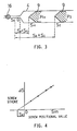
- the reciprocal of the filling density ⁇ of plasticized synthetic resin is a specific volume value, which is expressed as a function of the pressure value when the temperature is fixed.
- the formula for relation between pressure value (P) and specific volume value (V) of plasticized synthetic resin (hereinafter referred to as the PV relation formula) has been obtained in advance, it is possible to determine the injection weight G of the plasticized synthetic resin from the cylinder, or the filling weight G' of the plasticized synthetic resin in the mold cavity, using the equation (1) below, from the positional value of the screw at the first stop position (before injection), the resin pressure value in the cylinder with the screw at the first stop position, the positional value of the screw at the second stop position (after injection and dwelling), and the resin pressure value in the cylinder with the screw at the second stop position.
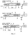
- a specified pressure is applied to the screw with the flow path closing mechanism between the injection molder cylinder and the mold cavity closed. Then, the check valve at the front end of the screw is closed or kept closed, and the screw compresses the plasticized synthetic resin in front of the screw, makes a balancing movement, and stops at a point where the pushing pressure equilibrates with the resilience of the plasticized synthetic resin to be compressed, namely at the first stop position.
- the plasticized synthetic resin in front of the screw in the cylinder provides a specified resin pressure determined by the pushing pressure applied to the screw at the first stop position. The positional value of the screw before injection and the resin pressure value in the cylinder corresponding to this positional value are obtained under this specified resin pressure.
- the flow path closing mechanism is closed.
- the check valve at the front end of the screw is closed or kept closed, and the screw compresses the plasticized synthetic resin in front of the screw, makes a balancing movement, and stops at a point where the pushing pressure equilibrates with the resilience of the plasticized synthetic resin to be compressed, namely at the second stop position.
- the resin in front of the screw in the cylinder provides a specified resin pressure determined by the pressure applied to the screw at the second stop position. The positional value of the screw after injection and dwelling, and the resin pressure value in the cylinder corresponding to this second positional value are obtained under this specified resin pressure.
- the specific volume value of the resin under each of these specified resin pressures is obtained by using the PV relation formula.
- the filling weight is then obtained through operation of the equation (1), on the basis of the thus obtained specific volume values and the positional values of the screw at the first and second stop positions.
- a specified pressure is applied to the screw with the flow path closing mechanism in the closed state so that the check valve is closed or kept closed and that a specified resin pressure is generated in the plasticized synthetic resin.
- the injection or filling weight is obtained through operations on the basis of the positional values of the screw at the first and second stop positions, and the resin pressure values in the cylinder corresponding to the respective positional values. Accordingly, it is possible to detect the filling weight of the resin in the mold cavity at a high accuracy on the injection molder side in the continuous molding production process.
- the flow path closing mechanism is closed when the specified resin pressures are generated to obtain the positional values of the screw at the first and second stop positions and the resin pressure values in the cylinder corresponding to the respective positional values. Therefore, the pressure applied to the screw does not influence finished products. In other words, the filling weight can be detected accurately regardless of the molding conditions.
- the specific volume values are obtained from the PV relation formula for plasticized synthetic resin at a constant temperature.
- the resin temperature can fluctuate as the ambient temperature changes with time.
- the resin temperature influences the specific volume values of the resin.
- PVT relation formula the formula for relation among pressure value (P), specific volume value (V) and temperature (T) of plasticized synthetic resin
- the specific volume value for pressure P I1 and temperature T I1 is expressed as V(P I1 , T I1 ), and that for P H1 and T H1 as V(P H1 , T H1 ).
- the detection method of the present invention may be designed so that an abnormality signal is emitted if the filling weight thus obtained in the above method is out of the preset range. With such abnormality signal, it is possible to know whether or not the product has been molded properly.
- Figs. 1 through 6 explain a preferred embodiment of the method of detecting the filling weight for an injection molder according to the present invention:
- an injection molder 2 is connected through a nozzle 3 with a mold 1 in which a product is to be injection-molded.
- the injection molder 2 has a cylinder 4 containing a screw 8. Synthetic resin pellets supplied through a hopper 5 are melted and kneaded by the screw 8 in the heated cylinder 4 while the molten resin is forced out by the screw 8 into the cavity 7 of the mold 1 through a flow path 6 formed in the nozzle 3.
- a check valve 9 is provided at the front end of the screw 8.
- the screw 8 is rotated by a screw-driving motor 10, for melting and kneading the synthetic resin pellets.
- the screw 8 is driven, under specified pressures applied by an injection piston 14, for reciprocating motion with respect to the nozzle 3 including balancing movements, thereby injecting the molten plasticized synthetic resin into the cavity 7 of the mold 1.
- the injection piston 14 is operated by means of oil pressure controlled by an electromagnetic flow valve 11 and an electromagnetic pressure valve 12 both of which are operated by a controller 13. 15 is a pressure oil source.
- a block valve 16 is provided in the flow path 6 of the nozzle 3 so as to block the flow of molten plasticized synthetic resin.
- the block valve 16 is operated by a driving unit 17 which is also controlled by the controller 13.
- Positional data of the screw 8 in the cylinder 4 is given from a screw position detector 18 to the controller 13.
- the controller 13 On the basis of the positional data of the screw 8 given by the screw position detector 18, the controller 13 operates the electromagnetic flow valve 11, electromagnetic pressure valve 12 and driving unit 17 according to a specified program, thus driving the screw 8 for reciprocating motion with respect to the nozzle 3 including the balancing movement, applying specified pressures to the screw 8, and operating the block valve 16.
- the screw position detector 18 also sends positional data of the screw 8 in the cylinder 4 to a processor 19.
- the processor 19 also receives pushing pressure data for the screw 8 from a screw pushing pressure detector 20, temperature data for the plasticized synthetic resin in the cylinder 4 from a resin temperature detector 21, and weight-related external data from an external input device 25.
- the processor 19 executes operations concerning the weight of the resin injected to fill in the cavity 7 of the mold 1, using the PV or PVT relation formula.
- the filling weight thus obtained is shown on a display 22, and compared by a comparator 23 with the normal filling weight range set in advance in a monitoring range setter 24. If the filling weight is out of the set range, the comparator 23 outputs an abnormality signal.
- the PVT relation formula is used in detecting the filling weight of plasticized synthetic resin in the mold cavity 7. If the PVT relation formula is known, it is possible to obtain the filling weight in the method described below. Even if the PVT relation formula is not known, the filling weight can be obtained easily in the method described later, by using the injection molder 2 of the present invention.
- each part of the injection molder is operated as follows:
- the block valve 16 is closed, and a specified pressure P I is applied through the injection piston 14 to the screw 8 with the block valve 16 closed. Under this pressure P I , the screw 8 is moved forward to compress the plasticized synthetic resin in front of the screw 8, makes a balancing movement, and stops at a first stop position where the pressure P I equilibrates with the resilience of the compressed plasticized synthetic resin.
- the screw position detector 18 detects the positional value S I of the screw at the first stop position of the screw 8, and sends it to the controller 13 and the processor 19.
- the resin temperature detector 21 detects the resin temperature T I1 of the plasticized synthetic resin with the screw 8 at the first stop position. Simultaneously, the screw pushing pressure detector 21 detects the pressure applied to the screw 8, or the resin pressure value P I1 determined by the pressure applied to the screw at the first stop position. All these data are supplied to the processor 19.
- the block valve 16 is opened, and the screw 8 is moved forward to inject the plasticized synthetic resin into the cavity 7 of the mold 1.
- the operation process of injecting the resin to fill in the mold cavity 7 is the same as that with a general injection molder.
- the block valve 16 is closed again, and a specified pressure P H is applied through the injection piston 14 to the screw 8. Similar to the operation before injection, the screw 8 makes a balancing movement under the pressure P H . Specifically, the screw 8 moves backward when the dwelling pressure is greater than the pressure P H , or moves forward when the dwelling pressure is smaller than P H , and stops at an equilibrating point or the second stop position.
- the screw position detector 18 detects the positional value S H of the screw 8 at the second stop position, and sends it to the controller 13 and the processor 19.
- the resin temperature detector 21 detects the temperature T H1 of the plasticized synthetic resin with the screw 8 at the second stop position, and the screw pushing pressure detector 21 detects the pressure applied to the screw 8 or the resin pressure value P H1 determined by the pressure applied to the screw at the second stop position. These data are all sent to the processor 19.
- the processor 19 calculates the specific volume value V(P I1 , T1) of the plasticized synthetic resin with the screw 8 at the first stop position, and the specific volume value V(P H1 , T1) with the screw 8 at the second stop position. Then, the filling weight G' of the resin in the mold cavity 7 or the injection weight G of the resin from the cylinder 4 is obtained through operations using the equation (1)'.
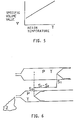
- the positional values S I and S H of the first and second stop positions are determined with the forward limit position of the screw 8 as a reference point, while the plasticized synthetic resin in the space between the front end of the screw 8 and the block valve 16 is compressed by the screw 8 under pressures of P I and P H . Therefore, the equation for obtaining an accurate injection weight G must take account of the capacity from the front end of the screw 8 at its forward limit position to the block valve 16, as indicated below.
- the value of S o can be obtained easily from the design values of the injection molder. If the design values are not known, the value of S o can be experimentally obtained in the following procedure: When a specified pressure is applied to the screw with the resin temperature maintained constant, the screw is moved forward to compress the plasticized synthetic resin in the cylinder. The screw stroke ⁇ S in this forward movement is proportional to the resin volume in the cylinder before application of the specified pressure or the positional value S m of the screw.
- the filling weight G' obtained from the equation (2) is shown on the display 22 and sent to the comparator 23, which compares the data with the normal filling weight range preset in the monitoring range setter 24 so as to judge whether or not the product has been molded properly. If the value is out of the preset range, the comparator 23 outputs an abnormal signal indicating a defective product.
- the temperature of plasticized synthetic resin is detected for each injection process, and the specific volume value of the resin is obtained at each detected temperature. If fluctuation in the resin temperature is small, the resin temperature may be detected at intervals of a specified number of injection processes. In such a case, the resin temperature detected for certain injection process may be used until the next detection.
- the filling weight G' of plasticized synthetic resin in the cavity 7 of the mold 1 is obtained to check whether or not moldings are formed normally. If the molding condition changes or is changed from the standard condition, the changed screw stroke value ⁇ S' may be obtained from the filling weight G' by using the following equations, and products may be monitored on the basis of the obtained ⁇ S'.
- V(P H1 , T o )/V(P o , T o ) f(P H1 /P o ) (4)'' According to these equations (4)' and
- the screw stroke value ⁇ S' obtained from the equation (3)''' is presented on the display 22, and sent to the comparator 23.
- the comparator 23 compares the value with the screw stroke range preset in the monitoring range setter 24; a normal screw stroke value ⁇ S plus a certain allowable screw stroke margin is preset as the screw stroke range. If the value is out of the preset range, an abnormal signal is output to indicate a defective product.
- the pressure applied to the screw 8 before injection is different from the one applied after injection and dwelling; P I before injection and P H after injection and dwelling.
- same pressure may be applied before injection and after injection and dwelling.
- a shutoff valve may be installed in the resin flow passage to the cavity 7 of the mold 1 instead of the block valve 16 in the flow path 6 of the nozzle 3.
- the value of the constant ⁇ can be determined from the equation (5)'.
- the resin pressure P is varied in multiple steps with the resin temperature maintained constant at T o .
- the varying resin pressure value is assumed to be P n .
- the value of constant ⁇ ' can be determined from the following equation (6):
- the value of constant R' can also be obtained from the equation (5)'.
- the PVT relation formula for plasticized synthetic resin can thus be obtained from the Spencer & Gilmore's equation.
- the block valve 16 is closed, and a specified pressure P is applied by the injection piston 14 to the screw 8 with the block valve 16 in the closed state. Under this pressure P, the screw 8 is moved forward to compress the plasticized synthetic resin in front of the screw 8, makes a balancing movement, and stops at a first stop position where the pressure P equilibrates with the resilience of the compressed plasticized synthetic resin.
- the screw position detector 18 detects the positional value S1 of the screw 8 at the first stop position, as a value corresponding to the amount of resin contained in the cylinder 4 in front of the screw 8 at the first stop position, and sends the detected value to the processor 19.
- the block valve 16 is closed, and the screw 8 is moved forward. After an appropriate amount of plasticized synthetic resin is injected, the block valve 16 is closed. The weight of the injected resin is measured by a weighing device (not shown), and the measured weight J is input to the processor 19 from the external input device 25.
- the block valve 16 is closed again, and a specified pressure P is applied by the injection piston 14 to the screw 8 in the closed state of the block valve 16. Similar to the operation in the first process, the screw 8 makes a balancing movement and stops at a second stop position under the pressure P.
- the screw position detector 18 detects the positional value S2 of the screw 8 at the second stop position, as a value corresponding to the amount of resin contained in the cylinder 4 in front of the screw 8 at the second stop position, and sends the value to the processor 19.
- the processor 19 performs operations to obtain the specific volume value V(P,T) of the plasticized synthetic resin at temperature T and pressure P, using the following equation (7): wherein
- the PVT relation formula thus obtained is based on the Spencer & Gilmore's equation.
- the PVT relation formula can also be obtained in other methods such as an experimental analytical method (method of successive approximation with multiple variables).
- the present invention permits highly accurate detection of the weight of plasticized synthetic resin injected to fill in a mold cavity. Therefore, the invention is useful to produce a plurality of moldings of constant quality simultaneously, using a form having a plurality of molding cavities therein.
Landscapes
- Engineering & Computer Science (AREA)
- Manufacturing & Machinery (AREA)
- Mechanical Engineering (AREA)
- Injection Moulding Of Plastics Or The Like (AREA)
Abstract
Procédé pour déterminer la charge de résine synthétique plastifiée devant être injectée et bloquée dans une cavité d'un moule par un cylindre d'une machine pour le moulage à injection. L'objectif est de déterminer la charge avec grande précision même dans le cas d'une machine pour le moulage à injection en continu. Les valeurs de serrage, les pressions et les températures sont observées quand la pression de la résine déchargée par le cylindre est maintenue à un niveau donné; une valve d'arrêt et une valve de retenue sont actionnées avant et après l'injection et le remplissage afin de déterminer la charge.
Applications Claiming Priority (3)
| Application Number | Priority Date | Filing Date | Title |
|---|---|---|---|
| JP64563/90 | 1990-03-14 | ||
| JP2064563A JP2918610B2 (ja) | 1990-03-14 | 1990-03-14 | 射出成形機の充填量検出方法 |
| PCT/JP1991/000337 WO1991013745A1 (fr) | 1990-03-14 | 1991-03-13 | Procede pour determiner la charge d'une machine pour le moulage a injection |
Publications (2)
| Publication Number | Publication Date |
|---|---|
| EP0594846A4 EP0594846A4 (fr) | 1992-03-03 |
| EP0594846A1 true EP0594846A1 (fr) | 1994-05-04 |
Family
ID=13261827
Family Applications (1)
| Application Number | Title | Priority Date | Filing Date |
|---|---|---|---|
| EP91906252A Withdrawn EP0594846A1 (fr) | 1990-03-14 | 1991-03-13 | Procede pour determiner la charge d'une machine pour le moulage a injection |
Country Status (8)
| Country | Link |
|---|---|
| US (1) | US5260010A (fr) |
| EP (1) | EP0594846A1 (fr) |
| JP (1) | JP2918610B2 (fr) |
| KR (1) | KR920700878A (fr) |
| CN (1) | CN1055698A (fr) |
| AU (1) | AU7482491A (fr) |
| CA (1) | CA2055449A1 (fr) |
| WO (1) | WO1991013745A1 (fr) |
Families Citing this family (20)
| Publication number | Priority date | Publication date | Assignee | Title |
|---|---|---|---|---|
| JPH0822562B2 (ja) * | 1990-05-24 | 1996-03-06 | 株式会社小松製作所 | 射出成形機のサイクル制御方法 |
| DE4038333A1 (de) * | 1990-12-01 | 1992-06-11 | Battenfeld Kunststoffmasch | Verfahren zum spritzgiessen von formteilen aus spritzgiessfaehigem kunststoff und vorrichtung zur durchfuehrung des verfahrens |
| US5370518A (en) * | 1992-01-29 | 1994-12-06 | Kabushiki Kaisha Komatsu Seisakusho | Apparatus for injection and compression molding |
| JP2628266B2 (ja) * | 1993-03-31 | 1997-07-09 | 日精樹脂工業株式会社 | 射出成形機の速度制御方法及び装置 |
| JP2770131B2 (ja) * | 1994-07-20 | 1998-06-25 | 日精樹脂工業株式会社 | 射出成形方法及び射出成形機 |
| JPH09123241A (ja) * | 1995-10-27 | 1997-05-13 | Sodick Co Ltd | スクリュプリプラ式射出成形装置の射出制御方法 |
| JP2003094485A (ja) * | 2001-09-25 | 2003-04-03 | Sumitomo Wiring Syst Ltd | 重量検査装置 |
| US20100230034A1 (en) * | 2006-06-28 | 2010-09-16 | Toyo Tire & Rubber Co., Ltd. | Process for producing tire through volume extrusion |
| CN102101352B (zh) * | 2010-12-22 | 2013-08-07 | 浙江大学 | 一种注塑成型制品重量无模型控制方法 |
| JP5647044B2 (ja) * | 2011-03-17 | 2014-12-24 | 住友重機械工業株式会社 | 射出成形機及び射出成形機の調整方法 |
| JP5823210B2 (ja) * | 2011-08-31 | 2015-11-25 | 住友重機械工業株式会社 | 射出成形機、および射出成形機の設定支援装置 |
| JP6186113B2 (ja) * | 2012-03-26 | 2017-08-23 | 住友重機械工業株式会社 | 射出成形機 |
| US9684295B2 (en) * | 2015-07-13 | 2017-06-20 | Coretech System Co., Ltd. | Molding system and method for operating the same |
| CN105150486B (zh) * | 2015-09-30 | 2017-11-28 | 重庆世纪精信实业(集团)有限公司 | 基于注塑系统施工同步的加工件消耗量统计方法以及系统 |
| DE102015117237B3 (de) | 2015-10-09 | 2017-03-23 | Kraussmaffei Technologies Gmbh | Verfahren zur Bestimmung eines realen Volumens einer spritzgießfähigen Masse in einem Spritzgießprozess |
| US11230043B2 (en) * | 2019-06-04 | 2022-01-25 | Coretech System Co., Ltd. | Method for setting molding conditions of injection-molding equipment |
| CN112895366B (zh) * | 2021-03-19 | 2022-02-11 | 珠海格力电器股份有限公司 | 一种注塑机的转保压位置确定方法和装置 |
| JP7567743B2 (ja) * | 2021-10-08 | 2024-10-16 | トヨタ自動車株式会社 | 中子造形装置、及び中子造形方法 |
| JP2024073987A (ja) * | 2022-11-18 | 2024-05-30 | 住友重機械工業株式会社 | 射出成形機の計測装置、及び射出成形機 |
| CN120886437B (zh) * | 2025-09-30 | 2025-12-12 | 宁波力松注塑科技有限公司 | 一种双螺杆注射射台 |
Family Cites Families (10)
| Publication number | Priority date | Publication date | Assignee | Title |
|---|---|---|---|---|
| US3750134A (en) * | 1971-02-11 | 1973-07-31 | Package Machinery Co | Plastic injection molding machine monitor |
| US3767339A (en) * | 1971-11-01 | 1973-10-23 | Hunkar Instr Dev Labor Inc | Injection molding control |
| US4714422A (en) * | 1984-05-22 | 1987-12-22 | Farrel Corporation | Rotary plasticator screw injection machine |
| JPS62184825A (ja) * | 1986-02-12 | 1987-08-13 | Japan Steel Works Ltd:The | 射出成形機の成形性能評価方法 |
| DE3783115T2 (de) * | 1986-03-27 | 1993-07-08 | Komatsu Mfg Co Ltd | Einspritzgiessmaschine. |
| JPS63150632A (ja) * | 1986-12-16 | 1988-06-23 | Sumitomo Heavy Ind Ltd | 射出成形機の消費樹脂重量計測方法 |
| SE462379B (sv) * | 1987-08-07 | 1990-06-18 | Bo Nilsson | Foerfarande foer styrning av vissa parametrar vid framstaellning av plastvaror |
| FR2625939B1 (fr) * | 1988-01-14 | 1990-05-04 | Seva | Procede et dispositif de moulage par injection de materiaux composites |
| JPH0637070B2 (ja) * | 1988-03-24 | 1994-05-18 | 株式会社小松製作所 | 射出圧縮成形機の成形装置および成形方法 |
| US4816197A (en) * | 1988-04-12 | 1989-03-28 | Hpm Corporation | Adaptive process control for injection molding |
-
1990
- 1990-03-14 JP JP2064563A patent/JP2918610B2/ja not_active Expired - Lifetime
-
1991
- 1991-03-13 CA CA002055449A patent/CA2055449A1/fr not_active Abandoned
- 1991-03-13 EP EP91906252A patent/EP0594846A1/fr not_active Withdrawn
- 1991-03-13 WO PCT/JP1991/000337 patent/WO1991013745A1/fr not_active Ceased
- 1991-03-13 US US07/773,637 patent/US5260010A/en not_active Expired - Fee Related
- 1991-03-13 AU AU74824/91A patent/AU7482491A/en not_active Abandoned
- 1991-03-14 CN CN91102098A patent/CN1055698A/zh active Pending
- 1991-11-13 KR KR1019910701601A patent/KR920700878A/ko not_active Withdrawn
Also Published As
| Publication number | Publication date |
|---|---|
| US5260010A (en) | 1993-11-09 |
| CN1055698A (zh) | 1991-10-30 |
| KR920700878A (ko) | 1992-08-10 |
| WO1991013745A1 (fr) | 1991-09-19 |
| CA2055449A1 (fr) | 1991-09-15 |
| JPH03264326A (ja) | 1991-11-25 |
| AU7482491A (en) | 1991-10-10 |
| JP2918610B2 (ja) | 1999-07-12 |
| EP0594846A4 (fr) | 1992-03-03 |
Similar Documents
| Publication | Publication Date | Title |
|---|---|---|
| EP0594846A1 (fr) | Procede pour determiner la charge d'une machine pour le moulage a injection | |
| EP1091842B1 (fr) | Technique de moulage automatise pour le moulage par injection de matieres thermoplastiques | |
| CN101318374B (zh) | 具有具备止回阀的螺杆的注塑成型机 | |
| US5178805A (en) | Method of controlling injection speed selecting points of injection molder | |
| EP0484549A1 (fr) | Procede pour regler le cycle de moulage d'une machine de moulage par injection | |
| US11213986B2 (en) | Method for determining an actual volume of an injection moldable compound in an injection molding process | |
| US6669459B2 (en) | Electric injection molding machine for controlling injection of electric injection molding machine | |
| US20200156300A1 (en) | Method for determining a value for the description of the compression of a moldable material | |
| EP0761409A1 (fr) | Procédé de simulation du comportement de la résine lors du moulage sous pression | |
| CN103481479B (zh) | 注塑成型机的压力控制装置 | |
| EP0473791A1 (fr) | Procede de commande de l'injection pour machines de moulage par injection | |
| US4850217A (en) | Adaptive process control for injection molding | |
| CN112172064A (zh) | 发泡成形方法和注塑成形机 | |
| EP0482199B1 (fr) | Procede de detection de caracteristiques de resine par machines de moulage par injection | |
| US5258147A (en) | Method of detecting injected amount from an injection molder | |
| JP3293425B2 (ja) | 射出低圧成形方法および装置 | |
| Nunn et al. | Adaptive process control for injection molding | |
| EP0493619B1 (fr) | Procede de detection d'un remplissage anormal dans une machine de moulage par injection | |
| US20060110489A1 (en) | Apparatus for measuring separation of mold parts | |
| US20210213663A1 (en) | Method for deriving bulk viscosity of molding material | |
| JPH08197594A (ja) | 射出成形方法 | |
| JPH08276476A (ja) | 射出プレス成形方法および射出プレス成形装置 |
Legal Events
| Date | Code | Title | Description |
|---|---|---|---|
| PUAI | Public reference made under article 153(3) epc to a published international application that has entered the european phase |
Free format text: ORIGINAL CODE: 0009012 |
|
| 17P | Request for examination filed |
Effective date: 19911112 |
|
| AK | Designated contracting states |
Kind code of ref document: A1 Designated state(s): DE FR GB IT |
|
| STAA | Information on the status of an ep patent application or granted ep patent |
Free format text: STATUS: THE APPLICATION IS DEEMED TO BE WITHDRAWN |
|
| 18D | Application deemed to be withdrawn |
Effective date: 19941001 |