EP0594848A1 - Progressive linse - Google Patents
Progressive linse Download PDFInfo
- Publication number
- EP0594848A1 EP0594848A1 EP92901906A EP92901906A EP0594848A1 EP 0594848 A1 EP0594848 A1 EP 0594848A1 EP 92901906 A EP92901906 A EP 92901906A EP 92901906 A EP92901906 A EP 92901906A EP 0594848 A1 EP0594848 A1 EP 0594848A1
- Authority
- EP
- European Patent Office
- Prior art keywords
- lens
- distance
- curvature
- refracting
- center
- Prior art date
- Legal status (The legal status is an assumption and is not a legal conclusion. Google has not performed a legal analysis and makes no representation as to the accuracy of the status listed.)
- Granted
Links
Images



Classifications
-
- G—PHYSICS
- G02—OPTICS
- G02C—SPECTACLES; SUNGLASSES OR GOGGLES INSOFAR AS THEY HAVE THE SAME FEATURES AS SPECTACLES; CONTACT LENSES
- G02C7/00—Optical parts
- G02C7/02—Lenses; Lens systems ; Methods of designing lenses
- G02C7/06—Lenses; Lens systems ; Methods of designing lenses bifocal; multifocal ; progressive
- G02C7/061—Spectacle lenses with progressively varying focal power
- G02C7/068—Special properties achieved by the combination of the front and back surfaces
-
- G—PHYSICS
- G02—OPTICS
- G02C—SPECTACLES; SUNGLASSES OR GOGGLES INSOFAR AS THEY HAVE THE SAME FEATURES AS SPECTACLES; CONTACT LENSES
- G02C7/00—Optical parts
- G02C7/02—Lenses; Lens systems ; Methods of designing lenses
- G02C7/06—Lenses; Lens systems ; Methods of designing lenses bifocal; multifocal ; progressive
- G02C7/061—Spectacle lenses with progressively varying focal power
Definitions
- the present invention relates to a configuration of a progressive power lens for correcting presbyopia, and particularly relates to a progressive power lens which is capable of reducing in weight and thickness as well as providing an excellent field of view by improving aberration thereof.
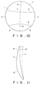
- conventional progressive power lenses consist of a region used for seeing relatively distant objects (hereinafter referred to as distant portion), a region for seeing relatively near objects (hereinafter referred to as reading portion), and a region, located between the distance portion and the reading portion, for seeing objects which are at intermediate distances. These portions are arranged as shown in FIG. 9A.
- the reference numeral 1 designates a distance portion, 2 a reading portion, and 3 an intermediate portion.
- the distance portion 1 and the intermediate portion are imaginally separated by the boundary line 5 whereas the intermediate portion and the reading portion 2 the boundary line 6.
- regions are however smoothly joined to each other, and there is no clear boundary line.
- each of the regions is substantially and horizontally divided by the principal gazing line.
- the principal gazing line is an imaginary line along the movement of the line of sight when the spectacles are put.
- objects are often watched in the vicinity of the principal gazing line, and this portion is particularly carefully designed in view of optical performance.
- FIG. 11 illustrates a section of this progressive power lens taken along the vertical principal gazing line which passes substatially centrally each of the regions previously described.
- the object side refracting interface 8 has a feature such that the lower portion of the lens is more bent toward the eyeball than the upper portion. For this reason, a lens which is thin in the reading portion and thick in the distance portion is, as indicated by the broken line 11 in FIG. 11, produced when the lens is produced according to the ordinary method without any prescription for prismatic power.
- a prism which has no object to correct squint of the base in the direction of 270° is put or provided, and processing is made as shown in the solid line 12, so that reduction in thickness is achieved not only in the distance portion but also in the whole lens.
- the present invention provides a progressive power lens which is capable of obtaining a good visual field by improving aberration thereof as well as smoothly joining the three regions.
- the present invention is characterized in that the curvature of at least one of the oppositely facing refracting interfaces of the distance portion is changed along principal gazing line 4 from the vicinity of the center to the peripheral portion of the lens according to a predetermined rule.
- one refracting interface 8 of the two oppositely facing refracting interfaces is reduced in curvature at a substantially constant rate from the vicinity of the center of the lens to the peripheral portion thereof, the one refracting interface being on the side of an object.
- one refracting interface 9 of the two oppositely facing refracting interfaces increases in curvature at a substantially constant rate from the vicinity of the center of the lens to the peripheral portion thereof, the one refracting interface being on the side of an eye ball.
- one refracting interface 8 of the two oppositely facing refracting interfaces increases in curvature from the vicinity of the center of the lens to the peripheral portion thereof, the one refracting interface being on the side of an object.
- one refracting interface 8 of the two oppositely facing refracting interfaces once increases and is then reduced in curvature from the vicinity of the center of the lens to the peripheral portion thereof, the one refracting interface being on the side of an object.
- one refracting interface 9 of the two oppositely facing refracting interfaces is reduced in curvature from the vicinity of the center of the lens to the peripheral portion thereof, the one refracting interface being on the side of an eye ball.
- one refracting interface 9 of the two oppositely facing refracting interfaces increases in curvature after once reduced, the one refracting interface being on the side of an eye ball.
- a progressive power lens which includes a distance portion 1 for looking a location at a relatively long distance, a reading portion 2 for looking a location at a relatively short distance, and an intermediate portion 3 between the distance portion and the reading portion for looking a location at a relatively intermediate distance, it is characterized in that the curvature of at least one of the oppositely facing refracting interfaces of the reading portion 2 changes along principal gazing line 4 from the vicinity of the center to the peripheral portion of the lens.
- the curvature of the distance portion 1 has a constant value at an interval of at least 12 mm from the vicinity of the center to the peripheral portion of the distance portion, and is then changed.
- the curvature of the reading portion 2 has a constant value at an interval of at least 7 mm from the vicinity of the center to the peripheral portion of the reading portion, and is then changed.
- a progressive power lens which has a prescription for correcting myopia in the distance portion region, characterized in that a prism, having a magnitude Pt, is provided with a base in the direction of 90°, the prism having no object to cure strabismus, the Pt satisfying the following relationship: where PW is the prescription for correcting myopia and ADD a addition power.
- the present invention is capable of achieving improvement in aberration which may be produced in corrective lenses, and the region which provides a good visual field is hence enlarged. Furthermore, the object side refractive interfaces may be freely set in curvature, and this enables reduction in weight and thickness and the appearance to be improved.
- the thinnest and lightest lens may be provided by adding a predetermined amount of a prism with the base in the direction of 90° when the lens is fitted into a frame, without deteriorating mechanical strength of the lens at all.
- FIG. 1A is a general view of a progressive power lens as a first embodiment of the present invention.
- the distance portion 1 has a refractive power of +3.00 dioptry (hereinafter referred to as D) whereas the reading portion 2 has a refractive power of +5.00 [D].
- the different in refractive power between the reading portion 2 and distance portion 1 is referred to as addition power, and the addition power of this embodiment is 2.00 [D].
- FIG. 1B A cross-section of the lens distance portion 1 taken along the principal gazing line is shown in FIG. 1B, in which the numeral 8 indicates a refracting interface on the object side of the lens, and 9 a refracting interface on the eyeball side.
- the refracting interface 8 of the present invention reduces in curvature from the vicinity of the center toward the peripheral portion of the lens.
- Table 1 shows curvatures of object side refracting interfaces of lenses of the present invention and the prior art.
- FIG. 1C shows a view of the astigmatism of a progressive power lens of the present invention.
- the distance portion 1 reduces in astigmatism in an upper peripheral portion thereof, and thus an area which gives a field of good view is widened.
- the object side refracting interface 8 is reduced in curvature, and hence as shown in FIG. 1B the thickness of the vicinity of the center of the lens is reduced. This provides an advantageous effect in reduction in weight and thickness.
- FIG. 2A is a sectional view of the distance portion of a second embodiment of the present invention.
- the object side refracting interface 8 is the same as the that of the conventional lens, the refracting interface of the eyeball side increases in curvature from the center toward the periphery. Table 2 shows the curvature of the eyeball side refracting interface of this embodiment.
- FIG. 2B is a sectional view of the reading portion 2. From an upper end point of the reading portion 2 toward the lower peripheral portion of the lens, the object side refracting interface 8 is reduced in curvature whereas the eyeball side refracting interface 9 increases in curvature. To facilitate the fabrication of the lens, in this embodiment the eyeball side refracting interface 9 is set to similarly change in curvature in both the distance portion 1 and the reading portion 2 but may be set to change differently in the distance portion and the reading portion.
- the object side refracting interface 8 increases in curvature toward the peripheral portion. Changes in curvature are given in Table 3. Table 3 Distance from the Center of Lens [mm] 0 10 20 30 40 Curvature of the Present Invention(m ⁇ 1) 1.68 2.02 2.52 3.03 2.69 Curvature of the Conventional Lens(m ⁇ 1) 1.68 1.68 1.68 1.68 1.68 1.68 1.68 1.68 1.68 1.68
- the lens increases in curvature to a distance of 30 mm from the center thereof, and decreases in curvature in the peripheral portion.
- FIG. 3B shows a sectional view of the reading portion of this embodiment.
- the curvature decreases toward the peripheral portion.
- FIG. 4A is a sectional view of the distance portion of a fourth embodiment of the present invention.
- this embodiment there is no change in curvature to a portion 12 mm away from the center, and the peripheral portion beyond 12mm the curvature increases.
- This provides a substantially constant refractive power within a range to a distance of 12mm from the center, and when spectacles slip down to some extent, they may be used without deteriorating visual power.
- FIG. 4B is a sectional veiw of the reading portion of this embodiment. There is no change in curvature from the upper end of the reading portion to a distance of 7mm, beyond which the curvature reduces in the peripheral portion. For this reason, to a distance of 7 mm from the upper end of the reading portion there is a region of which refractive power is constant.
- FIG. 5 is a sectional view of a progressive power lens of the present invention.
- an eyeball side refracting interface 11 is shown by the broken line in the case where a prism is provided with the base in the direction of 270° whereas an eyeball side refracting interface 12 is indicated by the dot-and-dash line in the case where a prism is placed with the base in the direction of 90° as in Japanese patent examined publication 2 (1990)-39769.
- Comparing the refracting interface 11 with the refracting interface 9 of the present invention in the distance portion 1 the lens with the refracting interface 11 is thinner whereas the lens of the present invention is thinner in both the intermediate portion and the reading portion 2.
- the present invention does not provide any effect of reduction in thickness. It is however to be noted that in the case where a progressive power lens is fitted in a frame as a spectacle lens, it is usual that as shown in FIG. 8 the fitting point O is set upwardly of the vertical center of the frame. The area of the distance portion region 1 thus becomes smaller than the area which puts areas of the intermediate portion region 3 and the reading portion region 2 together, and as a result reduction in thickness may be achieved.
- the prism is relatively large, and the lens excessively reduces in thickness at a lower portion of the reading portion. This reduces mechanical strength of the lens, and hence lenses may be destroyed or damaged during the processing of frame fitting, for example. To provide a sufficient thickness to the lower portion of the lens to avoid this, it is involved that the whole lens must be thick as indicated by the refracting interface 12 of FIG. 5.
- the refracting interfaces 8 and 9 are arranged substantially in parallel with each other over both the intermediate portion region 3 and the reading portion region 2, and it is thus possible to ensure the necessary minimum thickness from the center to the lower edge of the lens.
- This necessary minimum thickness depends on the strength of the lens material, and it is thus meaningless to equally set it.
- the vicinity of the center of the lens is generally the thinnest, and the thickness of this portion may be considered the minimum thickness which ensures the mechanical strength of the lens.
- the lens of the present invention has substantially equal thickness from the center to the reading portion lower edge, and the present invention is capable of provide the thinnest and the lightest lens which ensures the mechanical strength.
- the optimal prism Pt is given by the prescription for correcting myopia PW and addition power ADD of the distance portion as in Table 4 when the optimal prism Pt is set so that the lens has a substantially equal thickness from the center to the lower edge of the reading portion.
- Pt in Table 4 may be expressed as follows, using PW and ADD: The equation above shows that the value of Pt may be defined by PW ADD with a range. According to studies of the inventors, the largest effect for reduction in weight and thickness is achieved when Pt is set as given in Table 4, but it has been found that reduction in weight and thickness may be achieved as compared to conventional lens also when Pt is set within the range defined by the above equation.
- Pt has a unit of PD (prism diopter) and PW and ADD each have a unit of D (diopter).
- FIG. 6 illustrates a sectional view of a lens of this embodiment.
- the object side refracting interface 8 in the distance portion has the same curvature change as that described in the embodiment 3.
- the lens has a distance power of -6.00 [D], a addition power of 1.00 [D], and a refractive index of 1.56.
- the eyeball side refracting interface 9 is inclined so that the lens is provided with a prism of 4.00 [PD] having the base in the direction of 90°. In this embodiment, reduction in weight and thickness given by the eyeball side refracting interface 9 is added to that by the object side refracting interface 8, and thereby a very thin progressive power lens may be provided.
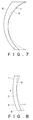
- FIG. 7 illustrates a sectional view of a lens of this embodiment.
- the distance power is -5.00 [D], the addition power 3.00 [D], and the refractive index 1.60.
- the object side refracting interface 8 has a constant curvature in the distance portion 1 as in conventional lens but the eyeball side refracting interface 9 varies in the distance portion as in Table 5.
- a prism of 2.50 [PD] is provided with the base in the direction of 90° for achieving reduction in weight and thickness.
- an example is given, having a spherical power of +3.50D, a addition power of 3.50D and a refractive index of 1.60.
- Table 6 shows curvature of the object side refracting interface in the distance portion. The curvature is constant from the center to a distance of 12 mm, beyond which it is reduced at a substantially constant rate.
- Table 6 Distance from the Center of Lens [mm] 0 3 6 9 12 15 18 21 Curvature of the Present Invention(m ⁇ 1) 10.0 10.0 10.0 10.0 10.0 9.7 9.4 9.2 Curvature of the Conventional Lens(m ⁇ 1) 10.0 10.0 10.0 10.0 10.0 10.0 10.0 10.0 10.0 10.0 10.0 10.0
- Table 7 indicates the curvature of the reading portion object side refracting interface of this embodiment.
- the progressive power zone is located within a distance of 16 mm from the center, and within this interval the curvature increases.
- the reading portion is in the peripheral side outside the interval of 16 mm.
- the curvature is constant in the interval of 7mm from the distance of 16 mm to 23 mm, and is constantly reduced in the peripheral portion beyond the distance of 23 mm.
- an example is given, having a spherical power of +3.50D, a addition power of 3.50D and a refractive index of 1.60.
- the lens is the same in the object side refracting interface as conventional progressive power lenses but the eyeball side refracting interface is constructed according to the present invention.
- Table 8 shows the curvature of the eyeball side refracting interface in the distance portion. The curvature is constant to a distance of 12 mm from the center, and is then increased at a substantially constant rate.
- Table 9 shows the curvature of the reading portion eyeball side refracting interface.
- the curvature is constant from the center to a distance of 23 mm, beyond which it increases at a predetermine rate. Since a progressive power zone is given in the range from the center to a distance 16 mm, the reading portion is constant in curvature within the range of 7 mm as described in the embodiment 8.
- Table 9 Distance from the Center of Lens [mm] 0 10 15 20 23 27 31 35 Curvature of the Present Invention(m ⁇ 1) 4.4 4.4 4.4 4.4 4.4 4.4 4.6 4.8 5.0
- an example is given, having a spherical power of -6.00D, a addition power of 3.50D and a refractive index of 1.60.
- Table 10 shows curvature of the object side refracting interface in the distance portion.
- the curvature is constant from the center to a distance of 15 mm, beyond which it is reduced to a distance of 35 mm at a substantially constant rate, and the curvature increases in the peripheral portion.
- Table 11 indicates the curvature of the reading portion object side refracting interface of this embodiment.
- the progressive power zone is located within a distance of 16 mm from the center, and within this interval the curvature is constant.
- the reading portion is in the peripheral side outside the interval of 16 mm.
- the curvature is constant in the interval of 7mm from the distance of 16 mm to 23 mm, and constantly increases in the peripheral portion beyond the distance of 23 mm.
- an example is given, having a spherical power of -6.00D, a addition power of 3.50D and a refractive index of 1.60.
- Table 12 shows curvature of the object side refracting interface in the distance portion.
- the curvature is constant from the center to a distance of 15 mm, beyond which it increases to a distance of 35 mm at a substantially constant rate, and the curvature reduces in the peripheral portion.
- Table 13 indicates the curvature of the reading portion object side refracting interface of this embodiment.
- the progressive power zone is located within a distance of 16 mm from the center, and within this interval the curvature increases.
- the reading portion is in the peripheral side outside the interval of 16 mm.
- the curvature is constant in the interval of 7mm from the distance of 16 mm to 23 mm, and constantly increases in the peripheral portion beyond the distance of 23 mm.
- progressive power lenses according to the present invention are suitable for lenses for correcting presbyopia, having three different areas; a distance portion, a reading portion, and an intermediate portion.
Landscapes
- Health & Medical Sciences (AREA)
- Ophthalmology & Optometry (AREA)
- Physics & Mathematics (AREA)
- General Health & Medical Sciences (AREA)
- General Physics & Mathematics (AREA)
- Optics & Photonics (AREA)
- Eyeglasses (AREA)
Applications Claiming Priority (7)
| Application Number | Priority Date | Filing Date | Title |
|---|---|---|---|
| JP40786390 | 1990-12-27 | ||
| JP407863/90 | 1990-12-27 | ||
| JP430491 | 1991-01-18 | ||
| JP4304/91 | 1991-01-18 | ||
| JP23634691 | 1991-09-17 | ||
| JP236346/91 | 1991-09-17 | ||
| PCT/JP1991/001759 WO1992012452A1 (fr) | 1990-12-27 | 1991-12-25 | Lentille progressive |
Publications (3)
| Publication Number | Publication Date |
|---|---|
| EP0594848A4 EP0594848A4 (de) | 1993-02-04 |
| EP0594848A1 true EP0594848A1 (de) | 1994-05-04 |
| EP0594848B1 EP0594848B1 (de) | 2006-03-15 |
Family
ID=27276206
Family Applications (1)
| Application Number | Title | Priority Date | Filing Date |
|---|---|---|---|
| EP92901906A Expired - Lifetime EP0594848B1 (de) | 1990-12-27 | 1991-12-25 | Progressive linse |
Country Status (4)
| Country | Link |
|---|---|
| US (1) | US5455642A (de) |
| EP (1) | EP0594848B1 (de) |
| DE (1) | DE69133517T2 (de) |
| WO (1) | WO1992012452A1 (de) |
Families Citing this family (11)
| Publication number | Priority date | Publication date | Assignee | Title |
|---|---|---|---|---|
| US5689324A (en) | 1992-08-18 | 1997-11-18 | Q2100, Inc. | Progressive lens |
| US6022498A (en) | 1996-04-19 | 2000-02-08 | Q2100, Inc. | Methods for eyeglass lens curing using ultraviolet light |
| US6280171B1 (en) | 1996-06-14 | 2001-08-28 | Q2100, Inc. | El apparatus for eyeglass lens curing using ultraviolet light |
| US6000798A (en) * | 1997-10-06 | 1999-12-14 | Innotech Inc. | Ophthalmic optic devices |
| US6149271A (en) * | 1998-10-23 | 2000-11-21 | Innotech, Inc. | Progressive addition lenses |
| US6505934B1 (en) * | 2001-04-27 | 2003-01-14 | Johnson & Johnson Vision Care, Inc. | Progressive addition lenses with prism power added to improve wearer comfort |
| US6827441B2 (en) | 2002-01-31 | 2004-12-07 | Opticlear Inc. | Progressive lens with reduced distortion |
| EP1990676B1 (de) * | 2002-05-28 | 2012-07-11 | Hoya Corporation | Biasphärisches Gleitsichtglas |
| EP2202561A1 (de) * | 2008-12-24 | 2010-06-30 | Essilor International (Compagnie Générale D'Optique) | Linsenindividualisierungsverfahren |
| US9256083B2 (en) | 2011-09-22 | 2016-02-09 | Ocular Technology Inc. | Multi-focal lens |
| JP6598695B2 (ja) * | 2016-01-26 | 2019-10-30 | 伊藤光学工業株式会社 | 眼鏡レンズ |
Family Cites Families (18)
| Publication number | Priority date | Publication date | Assignee | Title |
|---|---|---|---|---|
| FR2193989B2 (de) * | 1972-07-26 | 1975-03-07 | Essilor Int | |
| DE3016935C2 (de) * | 1980-05-02 | 1991-01-24 | Fa. Carl Zeiss, 7920 Heidenheim | Multifokale Brillenlinse mit gebietsweise gleitendem Brechwert |
| JPS57210320A (en) * | 1981-06-19 | 1982-12-23 | Hoya Corp | Progressive focus lens |
| JPS595841A (ja) * | 1982-07-02 | 1984-01-12 | Mitsubishi Electric Corp | 内燃機関燃料噴射装置 |
| JPS5958415A (ja) * | 1982-09-29 | 1984-04-04 | Seiko Epson Corp | 累進多焦点レンズ |
| JPH0239769B2 (ja) * | 1982-12-13 | 1990-09-07 | Seiko Epson Corp | Ruishintashotenrenzu |
| JPS6029724A (ja) * | 1983-07-29 | 1985-02-15 | Seiko Epson Corp | 累進多焦点レンズ |
| JPS6061719A (ja) * | 1983-09-16 | 1985-04-09 | Seiko Epson Corp | 累進多焦点レンズ |
| JPS6239769A (ja) * | 1985-08-15 | 1987-02-20 | Hitachi Ltd | 水中の全シリカの自動分析装置 |
| JPS6267501A (ja) * | 1985-09-19 | 1987-03-27 | Nippon Kogaku Kk <Nikon> | 光学用共重合体 |
| US5123725A (en) * | 1986-12-19 | 1992-06-23 | American Optical Corporation | Progressive addition spectacle lens |
| DE3716201C2 (de) * | 1987-05-14 | 2001-02-15 | Rodenstock Optik G | Progressives Brillenglas |
| JPH0812339B2 (ja) * | 1988-03-10 | 1996-02-07 | セイコーエプソン株式会社 | 眼鏡レンズ |
| DE68921432T2 (de) * | 1988-11-29 | 1995-08-10 | Seiko Epson Corp | Brillenlinse. |
| JP3273783B2 (ja) * | 1989-07-17 | 2002-04-15 | オプティッシェ.ウエルケ.ゲー.ローデンストック | 正の遠隔視覚パワーを有する眼鏡用プログレッシブレンズ |
| JPH066171A (ja) * | 1992-06-18 | 1994-01-14 | Matsushita Electric Ind Co Ltd | 弾性表面波フィルタ |
| JP2720715B2 (ja) * | 1992-06-22 | 1998-03-04 | ダイキン工業株式会社 | 極低温冷凍機 |
| JP2628486B2 (ja) * | 1992-09-30 | 1997-07-09 | 竹本油脂株式会社 | セメント用分散剤 |
-
1991
- 1991-12-25 WO PCT/JP1991/001759 patent/WO1992012452A1/ja not_active Ceased
- 1991-12-25 DE DE69133517T patent/DE69133517T2/de not_active Expired - Fee Related
- 1991-12-25 US US07/920,591 patent/US5455642A/en not_active Expired - Lifetime
- 1991-12-25 EP EP92901906A patent/EP0594848B1/de not_active Expired - Lifetime
Non-Patent Citations (1)
| Title |
|---|
| See references of WO9212452A1 * |
Also Published As
| Publication number | Publication date |
|---|---|
| WO1992012452A1 (fr) | 1992-07-23 |
| DE69133517D1 (de) | 2006-05-11 |
| US5455642A (en) | 1995-10-03 |
| EP0594848B1 (de) | 2006-03-15 |
| EP0594848A4 (de) | 1993-02-04 |
| DE69133517T2 (de) | 2006-08-10 |
Similar Documents
| Publication | Publication Date | Title |
|---|---|---|
| US6019470A (en) | Progressive multifocal lens and manufacturing method of eyeglass lens and progressive multifocal lens | |
| JP3170785B2 (ja) | 変動屈折率を具える眼鏡用レンズ | |
| KR100700652B1 (ko) | 굴절력 누진 증가면을 설계하는 방법, 당해 방법으로 형성한 굴절력 누진 증가면 및 당해 누진 증가면을 포함하는 안경용 렌즈 | |
| EP1379911B1 (de) | Progressive additionslinsen | |
| US5488442A (en) | Progressive multifocal ophthalmic lens | |
| KR100940699B1 (ko) | 누진 굴절력 렌즈 | |
| AU723308B2 (en) | Progressive power multi-focal lens | |
| JP2859055B2 (ja) | 眼鏡用のマルチフォーカルレンズ | |
| AU2002252366A1 (en) | Progressive addition lenses | |
| EP1026533A2 (de) | Progressive Zusatzlinsen mit regressiven Oberflächen | |
| EP1158337B1 (de) | Multifokal-Linse mit progressiver Brechkraft | |
| EP0594848B1 (de) | Progressive linse | |
| US6220704B1 (en) | Progressive power lens | |
| EP2762952A1 (de) | Linse mit progressiver brechkraft | |
| US5506630A (en) | Progressive multifocal lens | |
| JP3222528B2 (ja) | 非球面眼鏡レンズ | |
| JPH0812339B2 (ja) | 眼鏡レンズ | |
| US6964478B2 (en) | Progressive spectacle lens | |
| JP3038745B2 (ja) | 眼鏡レンズ | |
| EP0964285A1 (de) | Aspherische ophthalmische Linse | |
| JP2001318344A (ja) | 累進多焦点レンズ | |
| JP3226108B2 (ja) | 累進焦点レンズの製造方法 | |
| JP2011070234A (ja) | 累進屈折力レンズ | |
| JPH0693061B2 (ja) | 累進多焦点レンズ | |
| HK1026743A (en) | Progressive addition lenses having regressive surfaces |
Legal Events
| Date | Code | Title | Description |
|---|---|---|---|
| PUAI | Public reference made under article 153(3) epc to a published international application that has entered the european phase |
Free format text: ORIGINAL CODE: 0009012 |
|
| 17P | Request for examination filed |
Effective date: 19920904 |
|
| AK | Designated contracting states |
Kind code of ref document: A1 Designated state(s): DE FR GB |
|
| 17Q | First examination report despatched |
Effective date: 19951106 |
|
| APAB | Appeal dossier modified |
Free format text: ORIGINAL CODE: EPIDOS NOAPE |
|
| APAB | Appeal dossier modified |
Free format text: ORIGINAL CODE: EPIDOS NOAPE |
|
| APAD | Appeal reference recorded |
Free format text: ORIGINAL CODE: EPIDOS REFNE |
|
| APBZ | Receipt of observations in appeal recorded |
Free format text: ORIGINAL CODE: EPIDOSNOBA4E |
|
| APBH | Information on receipt of observation in appeal deleted |
Free format text: ORIGINAL CODE: EPIDOSDOBA4E |
|
| APBX | Invitation to file observations in appeal sent |
Free format text: ORIGINAL CODE: EPIDOSNOBA2E |
|
| APBZ | Receipt of observations in appeal recorded |
Free format text: ORIGINAL CODE: EPIDOSNOBA4E |
|
| APBT | Appeal procedure closed |
Free format text: ORIGINAL CODE: EPIDOSNNOA9E |
|
| GRAP | Despatch of communication of intention to grant a patent |
Free format text: ORIGINAL CODE: EPIDOSNIGR1 |
|
| GRAS | Grant fee paid |
Free format text: ORIGINAL CODE: EPIDOSNIGR3 |
|
| APAF | Appeal reference modified |
Free format text: ORIGINAL CODE: EPIDOSCREFNE |
|
| GRAA | (expected) grant |
Free format text: ORIGINAL CODE: 0009210 |
|
| AK | Designated contracting states |
Kind code of ref document: B1 Designated state(s): DE FR GB |
|
| REG | Reference to a national code |
Ref country code: GB Ref legal event code: FG4D |
|
| REF | Corresponds to: |
Ref document number: 69133517 Country of ref document: DE Date of ref document: 20060511 Kind code of ref document: P |
|
| ET | Fr: translation filed | ||
| PLBE | No opposition filed within time limit |
Free format text: ORIGINAL CODE: 0009261 |
|
| STAA | Information on the status of an ep patent application or granted ep patent |
Free format text: STATUS: NO OPPOSITION FILED WITHIN TIME LIMIT |
|
| 26N | No opposition filed |
Effective date: 20061218 |
|
| PGFP | Annual fee paid to national office [announced via postgrant information from national office to epo] |
Ref country code: DE Payment date: 20090129 Year of fee payment: 18 |
|
| PGFP | Annual fee paid to national office [announced via postgrant information from national office to epo] |
Ref country code: GB Payment date: 20081224 Year of fee payment: 18 |
|
| PGFP | Annual fee paid to national office [announced via postgrant information from national office to epo] |
Ref country code: FR Payment date: 20081215 Year of fee payment: 18 |
|
| GBPC | Gb: european patent ceased through non-payment of renewal fee |
Effective date: 20091225 |
|
| REG | Reference to a national code |
Ref country code: FR Ref legal event code: ST Effective date: 20100831 |
|
| PG25 | Lapsed in a contracting state [announced via postgrant information from national office to epo] |
Ref country code: FR Free format text: LAPSE BECAUSE OF NON-PAYMENT OF DUE FEES Effective date: 20091231 |
|
| PG25 | Lapsed in a contracting state [announced via postgrant information from national office to epo] |
Ref country code: DE Free format text: LAPSE BECAUSE OF NON-PAYMENT OF DUE FEES Effective date: 20100701 |
|
| PG25 | Lapsed in a contracting state [announced via postgrant information from national office to epo] |
Ref country code: GB Free format text: LAPSE BECAUSE OF NON-PAYMENT OF DUE FEES Effective date: 20091225 |