EP0594904A1 - Procédé et dispositif pour mélanger des matériaux plastiques de moulage - Google Patents
Procédé et dispositif pour mélanger des matériaux plastiques de moulage Download PDFInfo
- Publication number
- EP0594904A1 EP0594904A1 EP92309831A EP92309831A EP0594904A1 EP 0594904 A1 EP0594904 A1 EP 0594904A1 EP 92309831 A EP92309831 A EP 92309831A EP 92309831 A EP92309831 A EP 92309831A EP 0594904 A1 EP0594904 A1 EP 0594904A1
- Authority
- EP
- European Patent Office
- Prior art keywords
- subsidiary
- main
- blending
- materials
- amount
- Prior art date
- Legal status (The legal status is an assumption and is not a legal conclusion. Google has not performed a legal analysis and makes no representation as to the accuracy of the status listed.)
- Granted
Links
Images








Classifications
-
- B—PERFORMING OPERATIONS; TRANSPORTING
- B01—PHYSICAL OR CHEMICAL PROCESSES OR APPARATUS IN GENERAL
- B01F—MIXING, e.g. DISSOLVING, EMULSIFYING OR DISPERSING
- B01F35/00—Accessories for mixers; Auxiliary operations or auxiliary devices; Parts or details of general application
- B01F35/71—Feed mechanisms
- B01F35/714—Feed mechanisms for feeding predetermined amounts
- B01F35/7141—Feed mechanisms for feeding predetermined amounts using measuring chambers moving between a loading and unloading position, e.g. reciprocating feed frames
- B01F35/71411—Feed mechanisms for feeding predetermined amounts using measuring chambers moving between a loading and unloading position, e.g. reciprocating feed frames rotating or oscillating about an axis
-
- B—PERFORMING OPERATIONS; TRANSPORTING
- B01—PHYSICAL OR CHEMICAL PROCESSES OR APPARATUS IN GENERAL
- B01F—MIXING, e.g. DISSOLVING, EMULSIFYING OR DISPERSING
- B01F35/00—Accessories for mixers; Auxiliary operations or auxiliary devices; Parts or details of general application
- B01F35/80—Forming a predetermined ratio of the substances to be mixed
- B01F35/88—Forming a predetermined ratio of the substances to be mixed by feeding the materials batchwise
- B01F35/882—Forming a predetermined ratio of the substances to be mixed by feeding the materials batchwise using measuring chambers, e.g. volumetric pumps, for feeding the substances
Definitions
- the present invention relates to a method and apparatus for blending plastic molding materials by setting blending ratios of main materials such as virgin materials (natural pellets) for plastic molding to subsidiary materials such as coloring agents like a master batch.
- a rotating disc type metering feeder which is adapted to perform the blending by vertically moving a scraper to a volumetric metering chamber formed on rotating disc.
- a plastic resin material is generally defined as a main material
- a coloring agent, plasticizer, flame retardant or the like which is added to a raw material is defined as a subsidiary material.
- a material with a higher blending ratio should be reasonably defined as a main material
- a material with a lower blending ratio as a subsidiary material.
- Plural supplemental materials may be classified into a main material and a subsidiary material by such distinguishing method.
- the invention enables a continuous molding without loss even in extrusion molding, and an automatic adjustment of amount desired to be blended by a scraper without need of manpower, thereby increasing precision of blending main and subsidiary materials.
- the invention allows to obtain a higher quality product, and contributes to reduction of cost for subsidiary materials, as it avoids waste of subsidiary materials which are low in blending ratio and expensive.
- the invention presents a method for blending plastic molding materials by setting a blending ratio of main material to subsidiary material, wherein a blending amount of subsidiary or main material to main or subsidiary material is automatically set by calculating the amount required of either the main and subsidiary materials to the other based on a measured value and/or scale factor of either the subsidiary or main material, and inputting at least one point of stroke amounts of a scraper for the main or subsidiary material corresponding to the amount required as a measured data of the main or subsidiary material.
- two points that is, the minimum and maximum values, or three or more points may be inputted, or inputs may be dependent on the bulk density of a material.
- a type of virgin material, type and scale factor of coloring agent, scraper position for the virgin material are prestored in memory with relation to a tradename or code number of product so that blending amount of the virgin material to the coloring agent is automatically set by selecting the tradename or code number of product.
- a color change is achieved by a color change signal and a selection of product tradename.
- a material currently used is automatically switched to a different material by a material change signal.
- the invention presents an apparatus comprising a base having material discharge ports and a space for containing a rotating disc; the rotating disc rotatably contained in said space and having two or more lines of plural metering chambers in a concentric circle; one or plural material discharge port for measuring, blending and discharging materials fed to the lines of the metering chambers by rotatively displacing the materials; a chute for concentrating the material discharge ports in one place; scrapers for adjusting a feeding amount of main or subsidiary material metered in said metering chambers; and a microcomputer for automatically setting a blending amount of main or subsidiary material to subsidiary or main material by calculating an amount required of either main and subsidiary materials to the other based on the measured value and/or scale factor of either the subsidiary or main material, and inputting at least one point of stroke amounts of a scraper for the main or subsidiary material corresponding to the amount required as a measured data of the main or subsidiary material.
- the metering value and/or scale factor of either the subsidiary or main material, blending rate of the other material, stroke amount of the scrapers, type of the main or subsidiary material with relation to tradename or code number of a product, type and scale factor of the coloring agent and other necessary data are inputted in the microcomputer.
- the chute is preferably detachable from the material discharge port in the base.
- the metering chambers of the lines on the rotating disc and the material discharge ports in the base are incommunication with air injection pipes by way of ducts connected to an air supply source, so that compressed air from the air supply source is injected to the metering chambers and the material discharge ports. After metering is completed, the compressed air is blown to the metering chambers, material discharge ports and chute to prevent materials and dusts from adhering thereto.
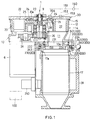
- Fig. 1 is a sectional view of a volumetric metering and blending apparatus and chute used for a method of the invention.
- Fig. 2 is a top plan view of Fig. 1 with the cover removed, showing the metering start position.
- Fig. 3 is a plan view showing a rotating disc rotated to the metering completed position from the state shown in Fig. 2.
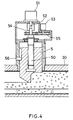
- Fig. 4 is a sectional view about a scraper.
- Fig. 5 is an exploded perspective view schematically showing the metering and blending apparatus.
- Fig. 6 is a block diagram of a control system.
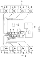
- Fig. 7 is a schematic front view comprehensively showing an embodiment of the invention.
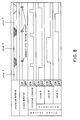
- Fig. 8 is an operational chart for extrusion molding.
- Fig. 9 is an operational chart for injection molding.
- Fig. 10 is a schematic front view comprehensively showing another embodiment of the invention.
- Fig. 11 is an operational chart for extrusion molding.
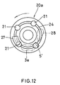
- Fig. 12 is a plan view showing an inner rotating disc.
- Fig. 13 is a developed sectional side view showing a portion of inner rotating disc.
- Fig. 14 is a disassembled perspective view of a detachment mechanism.
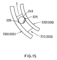
- Fig. 15 is a plan view showing positioning means for a slide ring and slide ring case.
- a volumetric metering and blending apparatus indicated by reference numeral 1 comprises a base 10 having a material discharge port 11 and a space 12 for containing a rotating disc; the rotating disc 20 rotatably contained in the space 12 and having two lines L1 and L2 of plural metering chambers 21 and 22 in a concentric circle; one or plural material discharge ports 11 for measuring, blending and discharging materials fed to the lines L1 and L2 of the metering chambers 21 and 22 by rotatively displacing the materials; a chute 17 for concentrating the material discharge ports 11 in one place; scrapers 5 and 5' for adjusting a feeding amount of main or subsidiary material metered in the metering chambers 21 and 22; and a cover 30 for covering the rotating disc 20 and having material supply sources 2 and 3, which contain such materials as powdered raw plastic materials or coloring agents, by way of flange joints.
- the rotating disc 20 has two or more (two in the embodiment) lines L1, L2 of plural metering chambers 21 ⁇ 21, 22 ⁇ 22 comprising through-holes circumferentially formed with equal spacing therebetween on concentric different circles from the center toward the outer circumference thereof, and the metering chambers 21 and 22 are rendered to be equal or unequal in unit volume.
- the shape, diameter, depth, volume, number, location and the like of the unit metering chamber 21, 22 in the lines L1, L2 ⁇ are optional. Alternately, a circular groove (not shown) may be employed instead of the metering chambers 21 ⁇ 21, 22 ⁇ 22.
- the rotating disc is divided into an outer rotating disc 20 and an inner rotating disc 20a separatedly, it may be formed integrally.
- the inner rotating disc 20a has a circular concave groove 24 formed thereon to avoid galling.
- a supply port 20a of first material supply source 2 for feeding such material A as natural pellets (a main material) is provided at a selected position along the first line L1, and a scraper 5 is placed on the rotating disc 20 at the downstream side of first material supply source 2 so that it freely moves in the vertical direction to provide a desired measured value.
- a supply port 3a of second material supply source 3 for feeding such material B as a coloring agent like master batch (a subsidiary material) is provided in a selected position along the second line L2 at the downstream side of first material supply source 2.
- a scraper 5' may be placed on the rotating disc 20 at the downstream side of second material supply source 3.
- the number of material supply sources is not limited to two as above, but may be three or more optionally.
- a small cylinder 23 is suspended centrally in the lower part of rotating disc 20 (20a), and a pivot is inserted through the small cylinder 23 thereabove and connected therewith by a nut 9 or the like in the upper part, while the lower part of the pivot is supported by a bearing 8 which is further connected to a driving source 6 by way of a gear system 26.
- Either connecting methods between the base 10 and the rotating disc 20, and between the rotating disc 20 and the pivot 7 are optional and not limited to be as structured in the embodiment.
- the base 10 has a outer circumferential wall 14 in the upper direction formed thereon, and a circular step 15 is formed in the outer circumference of the outer wall 14 on the upper end to engage with a cover 30 such that it is trapped therein.
- a cover 30 such that it is trapped therein.
- Below the planar part of base 10 is formed one or plural material discharge port 11, whereby materials fed to the metering chambers 21, 22 ⁇ of the lines L1, L2 ⁇ are blended and discharged by rotational displacements, and a chute 17 concentrating the material discharge port 11 in one place is connected therewith in the lower part.
- the scraper 5 is engaged with a driving shaft 50 forming, for example, a trapezoidal screw thread, as shown in Fig. 4, and coupled to a driving source 51 so that the displacement amount of the scraper can be changed.
- the driving source 51 is provided with a gear 54 on an output shaft 52 thereof to rotate a potentiometer (PM) 53 for position detection, wherein the gear 54 is in engagement with a gear 55 of the potentiometer 53.
- the scraper 5 is guided by a pin 56 provided for vertical movement thereof with the direction maintained constant.
- a position detecting means for example, an encoder or the like may be employed instead of the potentiometer 53.
- Numeral 100 in Figs. 1 and 6 shows a microcomputer.
- the microcomputer 100 has in its memory the measured value and/or scale factor of either subsidiary or main material, blending ratio of the other material, at least one point of stroke amount of the scrapers 5, 5', type of a main or subsidiary material with relation to tradename or code number of a product, type and scale factor of a coloring agent and other necessary data through a setter 101, analog-to-digital (A/D) converter 102 or the like.
- the measured data may be automatically inputted, as shown in Fig. 6, by an electronic scale 103, host computer or plastic machine 104 or the like.
- a central processing unit is indicated by numeral 105, a random access memory by numeral 106, and a read only memory by numeral 107.
- one point or the maximum or minimum value of stroke amount of the scraper 5 is stored in memory as a detection value of the potentiometer 53, so that a position within the variable amount can be optionally detected (as a motion stroke amount) for movement.
- the measured data at the minimum stroke position of scraper 5 (the lowest position to the table) and the maximum stroke position of scraper 5 are inputted with relation to the virgin material. If the discharge amount is not proportional to the changing position of scraper 5, a higher precision can be obtained by inputting several data taken at optional positions.
- the invention enables to automatically set a blending amount of virgin material to a coloring agent by prestoring type of the virgin material, type and scale factor of the coloring agent, positioning of the scraper for virgin material and the like with relation to tradename or code number of a product into memory and designating the tradename or code number of product.
- the data of the above embodiment are registered and stored in memory by material used, for example, by tradename or code number of products.
- material used for example, by tradename or code number of products.
- it can be automatically reset by accessing to the data registered and stored in memory.
- An embodiment of the control block is as shown in Fig. 6.
- the invention enables to change colors by designating a color change signal and trademark of a product. This is applicable when producing products of different tradenames with virgin material and master batch of a same material except scale factors of the master batch being different. By designating tradename of the product and accessing to the measured data, scale factor of master batch and positioning of the scraper for virgin material, which are registered, the discharge amount of virgin material and positioning of the scraper are automatically set for color changing.
- Fig. 7 shows an exemplary apparatus for the above method, wherein a virgin material contained in a first material supply source 2 is fed to a volumetric metering and blending apparatus 1 through a charging hopper 64 and receiving hopper 4 by suction force of a suction air source 18.
- a coloring agent such as master batch in second material supply sources 3 ⁇ 3 is fed to the volumetric metering and blending apparatus 1 through pipings and a collector 60 for multiple materials switching by air from an air source 65 of pressure feed type.
- a chute is depicted by numeral 17, a plastic machine by numeral 19 and an opening and closing valve by numeral 66.
- Fig. 8 is an operational chart for extrusion molding. In this case, a color change command is provided by a host computer, extruder or the like, designating a tradename of succeeding product.
- Fig. 9 shows an operational chart for injection molding.
- a collector 60 for multiple materials switching is provided on the side of master batch material so that plural master batch materials of different colors can be supplied and the molding operation is discontinuously performed, and air purging means 61 is provided, as shown in Fig. 7, for purging at the side of plastic machine 19.
- a color change command is provided by the plastic machine 19, host computer or the like.
- the invention also enables to automatically switch from a material currently used to a different material by means of a material change signal. In this case, switching between different virgin materials may be possible as well.
- Figs. 10 and 11 show another embodiment having a collector 60 for multiple materials switching at the side of virgin material as well to allow material changing by both collectors, wherein same parts being depicted by same numerals as in Fig 7 for convenience.
- an air source is indicated by numeral 67, and an opening and closing valve by numeral 68.
- Fig. 11 is an operational chart for extrusion molding in the arrangement shown in Fig. 10.
- material A, purging material and material B are inclusively depicted by numeral 62, and material B, purging material and material C by numeral 63.
- the inner rotating disc 20a is fitted into an accommodation chamber 25 formed centrally in the upper part of outer rotating disc 20.
- the inner rotating disc 20a has the above-mentioned circular concave groove 24, plural metering chambers 21 formed in orthogonal relationship with the circular concave groove 24, a scraper 5' provided depending on requirement and scraping means 27 for scraping off materials adhered inside the circular concave groove 24.
- each of the metering chamber 21 is positioned at the material outlet 28 for subsidiary material formed in the outer rotating disc 20, it comes into communication with the material discharge port 11 in the base 10, and the subsidiary material is metered in such communicating state and dropped to the chute 17 through the material discharge port 11.
- the circular concave groove 24 is slightly larger in width and height than the maximum length of material particle to be metered and blended.
- the scraping means 27 is provided at a position with a spacing of one metering chamber 21 or larger spacing from the material outlet 28. As shown in Fig 13, for example, the scraping means 27 is mounted to be fitted in the circular concave groove 24 in the cover 30, so that the material adhering inside the circular concave groove 24 is scraped off into the metering chamber 21 touching to the front 27a of scraping means 27 by rotational movement of the rotating disc 20a. In this way, precision in metering the material is improved.
- the rotating disk 20 is provided with a scraping means 29 on the outer rotating disc 20 between the material supply port 2a and the material discharge port 11 in the base 10.
- a scraping means 29 on the outer rotating disc 20 between the material supply port 2a and the material discharge port 11 in the base 10.
- the chute 17 is easily detachable to the material discharge port 11 in the base 10 by means of a detachment mechanism 200, wherefore such advantages as cleaning being facilitated can be obtained.
- the detachment mechanism 200 having such a structure as shown in Figs. 1, 14 and 15 is described below.
- the detachment mechanism 200 comprises a slide ring 210 having plural tapered concave parts 211, 212 and 213 formed with a selected spacing on the upper surface thereof and a threaded hole 214 through which a shaft 241 of a handle 240 is inserted; a slide pipe 220 fitted into the slide ring 210 and having outward flanges 221, 222 and 223 formed to face the tapered concave parts 211, 212 and 213; and a slide ring case 230 having, in the center thereof, a conduit port 231 in communication with the material discharge port 11 in the base 10 and a ring-shaped empty chamber 232 fitted to the slide ring 210 and slide pie 220 in the circumferential direction, and combined with the lower surface of base 10 in the upper surface thereof by means of a bolter the like.
- a bolt hole is indicated by numeral 233, and a slide hole for horizontal rotation of the shaft 241 of handle 240 by numeral 234, wherefore the handle 240 is inserted through the slide hole 234 and screwed fixedly in the threaded hole 214.
- a spring 242 is provided between the upper surface 224 except the outward flanges 221 to 223 of slide pipe 220 and the bottom surface 10a of base 10, so that the slide pipe 220 is always lowered by the spring 242.
- the slide pipe 220 comes to the lowest position, when the ball 243 is at the lowest position a in the tapered concave parts 211 to 213, and is set at an open edge 17a of the chute 17 pressure-fitted thereto. In this state, V-shaped grooves 225 and 235 as shown in Fig.
- chute 15 are formed outside the outward flanges 221 to 223 of slide pipe 220 and inside the empty chamber 232 of slide ring case 230, and the slide pipe 220 is prevented from rotating by placing the ball 243 in engagement between both V-shaped grooves 225 and 235.
- the slide ring 210 moves upward against the pressing force of spring 242 and the pressure fitting between the lower end of pipe 220 and the open edge 17a of chute 17 is released, the chute 17 can be removed holding the grip 31.
- air injection pipes 153, 154 and 156 are provided in communcation with the metering chambers 21 and 22 in lines L1 and L2 of the rotating disc 20 and the material discharge port 11 in the base 10 by way of ducts 151, 152 and 155 connected to the air source 150, so that compressed air is injected to the metering chambers 21 and 22, and the material discharge port 11, in order to prevent materials from adhering to the metering chambers 21 and 22 and the material discharge port 11.
- a level sensor is indicated by numeral 250.
- a crushed material supply port 260 may be employed in the metering chamber 22, as shown in Fig. 2, so that three types of materials can be metered and blended.
Landscapes
- Chemical & Material Sciences (AREA)
- Chemical Kinetics & Catalysis (AREA)
- Processing And Handling Of Plastics And Other Materials For Molding In General (AREA)
Priority Applications (3)
| Application Number | Priority Date | Filing Date | Title |
|---|---|---|---|
| AT92309831T ATE147657T1 (de) | 1992-10-27 | 1992-10-27 | Verfahren und vorrichtung zum mischen plastischer gussmaterialien |
| EP92309831A EP0594904B1 (fr) | 1992-10-27 | 1992-10-27 | Procédé et dispositif pour mélanger des matériaux plastiques de moulage |
| DE69216833T DE69216833T2 (de) | 1992-10-27 | 1992-10-27 | Verfahren und Vorrichtung zum Mischen plastischer Gussmaterialien |
Applications Claiming Priority (1)
| Application Number | Priority Date | Filing Date | Title |
|---|---|---|---|
| EP92309831A EP0594904B1 (fr) | 1992-10-27 | 1992-10-27 | Procédé et dispositif pour mélanger des matériaux plastiques de moulage |
Publications (2)
| Publication Number | Publication Date |
|---|---|
| EP0594904A1 true EP0594904A1 (fr) | 1994-05-04 |
| EP0594904B1 EP0594904B1 (fr) | 1997-01-15 |
Family
ID=8211530
Family Applications (1)
| Application Number | Title | Priority Date | Filing Date |
|---|---|---|---|
| EP92309831A Expired - Lifetime EP0594904B1 (fr) | 1992-10-27 | 1992-10-27 | Procédé et dispositif pour mélanger des matériaux plastiques de moulage |
Country Status (3)
| Country | Link |
|---|---|
| EP (1) | EP0594904B1 (fr) |
| AT (1) | ATE147657T1 (fr) |
| DE (1) | DE69216833T2 (fr) |
Cited By (1)
| Publication number | Priority date | Publication date | Assignee | Title |
|---|---|---|---|---|
| JP2019199354A (ja) * | 2018-05-18 | 2019-11-21 | 株式会社ヨシカワ | バッチ計量供給装置 |
Families Citing this family (1)
| Publication number | Priority date | Publication date | Assignee | Title |
|---|---|---|---|---|
| CN111437766A (zh) * | 2020-05-21 | 2020-07-24 | 重庆森盟新能源开发有限公司 | 一种便于清洗的铝材喷淋环保涂料生产用配比装置 |
Citations (6)
| Publication number | Priority date | Publication date | Assignee | Title |
|---|---|---|---|---|
| DE345426C (fr) * | ||||
| GB743424A (en) * | 1953-04-23 | 1956-01-18 | Keir & Cawder Ltd | Device and apparatus for controlled discharge of granular material |
| US3096909A (en) * | 1960-10-07 | 1963-07-09 | Hachler Walter | Device for weighing and dispensing materials for mixing thereof |
| GB1317412A (en) * | 1971-09-06 | 1973-05-16 | Anchor Hocking Corp | Mixing and metering apparatus |
| DE2416248A1 (de) * | 1974-04-03 | 1975-10-16 | Ver Foerderung Inst Kunststoff | Verfahren zum dosieren von mehreren unterschiedlichen rieselfaehigen schuettguetern, die dosiert in einem mischgefaess miteinander vermischt werden, und vorrichtung zur durchfuehrung des verfahrens |
| EP0394785A1 (fr) * | 1989-04-26 | 1990-10-31 | SAMI S.N.C. DI BERTOLINI CLAUDIO & C. | Moyens et procédé pour colorer automatiquement du béton |
-
1992
- 1992-10-27 EP EP92309831A patent/EP0594904B1/fr not_active Expired - Lifetime
- 1992-10-27 DE DE69216833T patent/DE69216833T2/de not_active Expired - Fee Related
- 1992-10-27 AT AT92309831T patent/ATE147657T1/de not_active IP Right Cessation
Patent Citations (6)
| Publication number | Priority date | Publication date | Assignee | Title |
|---|---|---|---|---|
| DE345426C (fr) * | ||||
| GB743424A (en) * | 1953-04-23 | 1956-01-18 | Keir & Cawder Ltd | Device and apparatus for controlled discharge of granular material |
| US3096909A (en) * | 1960-10-07 | 1963-07-09 | Hachler Walter | Device for weighing and dispensing materials for mixing thereof |
| GB1317412A (en) * | 1971-09-06 | 1973-05-16 | Anchor Hocking Corp | Mixing and metering apparatus |
| DE2416248A1 (de) * | 1974-04-03 | 1975-10-16 | Ver Foerderung Inst Kunststoff | Verfahren zum dosieren von mehreren unterschiedlichen rieselfaehigen schuettguetern, die dosiert in einem mischgefaess miteinander vermischt werden, und vorrichtung zur durchfuehrung des verfahrens |
| EP0394785A1 (fr) * | 1989-04-26 | 1990-10-31 | SAMI S.N.C. DI BERTOLINI CLAUDIO & C. | Moyens et procédé pour colorer automatiquement du béton |
Cited By (4)
| Publication number | Priority date | Publication date | Assignee | Title |
|---|---|---|---|---|
| JP2019199354A (ja) * | 2018-05-18 | 2019-11-21 | 株式会社ヨシカワ | バッチ計量供給装置 |
| WO2019220854A1 (fr) * | 2018-05-18 | 2019-11-21 | 株式会社ヨシカワ | Dispositif d'alimentation de pesée de lot et son procédé de fonctionnement |
| AU2019268654B2 (en) * | 2018-05-18 | 2021-09-02 | Yoshikawa Corporation | Batch-weighing feeding device and method for operating same |
| US11788876B2 (en) | 2018-05-18 | 2023-10-17 | Yoshikawa Corporation | Batch weighing/supply device, and operating method therefor |
Also Published As
| Publication number | Publication date |
|---|---|
| DE69216833D1 (de) | 1997-02-27 |
| ATE147657T1 (de) | 1997-02-15 |
| DE69216833T2 (de) | 1997-05-07 |
| EP0594904B1 (fr) | 1997-01-15 |
Similar Documents
| Publication | Publication Date | Title |
|---|---|---|
| US5110521A (en) | Hybrid apparatus and method for blending materials | |
| US6203184B1 (en) | Blender | |
| EP0789617B1 (fr) | Appareil de melange de materiaux | |
| EP0761410B1 (fr) | Appareil de mélange | |
| US4983090A (en) | System for feeding bulk material | |
| JP3315990B2 (ja) | 自己移送及び急速移送又は掃除のための手段を有する乾燥固体の計量装置 | |
| US7748575B2 (en) | Screw type material feeding apparatus | |
| EP0594904B1 (fr) | Procédé et dispositif pour mélanger des matériaux plastiques de moulage | |
| GB2087366A (en) | Apparatus for metering semi-flowable material | |
| WO1998005932A1 (fr) | Systeme de dosage multirecette | |
| US3320639A (en) | Apparatus for blending powders | |
| JPH0785893B2 (ja) | 粒状の樹脂原料の計測式混合装置 | |
| US4135643A (en) | Ingredient metering flow tube and baffle for plastic raw materials mixer | |
| WO2024034727A1 (fr) | Pompe à vis pour pulvérulent ayant une précision de transfert améliorée, et procédé | |
| US4103357A (en) | Process and device for continuous metering and mixing | |
| CN213133048U (zh) | 一种计量混合一体机 | |
| JP2613151B2 (ja) | プラスチック成形材料の混合方法 | |
| CN211643931U (zh) | 一种油性粉状物料精确计量装置 | |
| US3664642A (en) | Mixing apparatus | |
| CN224159837U (zh) | 下料溜槽调节装置 | |
| CN224156794U (zh) | 一种矿渣微粉加工用配料装置 | |
| CN223733852U (zh) | 一种螺杆式定量混合装置 | |
| JPH0553619B2 (fr) | ||
| JPH0820299B2 (ja) | 回転円板型計量供給装置 | |
| JPH04176608A (ja) | 粉粒体原料の混合装置 |
Legal Events
| Date | Code | Title | Description |
|---|---|---|---|
| PUAI | Public reference made under article 153(3) epc to a published international application that has entered the european phase |
Free format text: ORIGINAL CODE: 0009012 |
|
| AK | Designated contracting states |
Kind code of ref document: A1 Designated state(s): AT CH DE FR GB IT LI |
|
| 17P | Request for examination filed |
Effective date: 19941028 |
|
| 17Q | First examination report despatched |
Effective date: 19950413 |
|
| GRAG | Despatch of communication of intention to grant |
Free format text: ORIGINAL CODE: EPIDOS AGRA |
|
| GRAH | Despatch of communication of intention to grant a patent |
Free format text: ORIGINAL CODE: EPIDOS IGRA |
|
| RAP1 | Party data changed (applicant data changed or rights of an application transferred) |
Owner name: MATSUI MANUFACTURING CO., LTD. |
|
| GRAH | Despatch of communication of intention to grant a patent |
Free format text: ORIGINAL CODE: EPIDOS IGRA |
|
| GRAA | (expected) grant |
Free format text: ORIGINAL CODE: 0009210 |
|
| ITF | It: translation for a ep patent filed | ||
| AK | Designated contracting states |
Kind code of ref document: B1 Designated state(s): AT CH DE FR GB IT LI |
|
| REF | Corresponds to: |
Ref document number: 147657 Country of ref document: AT Date of ref document: 19970215 Kind code of ref document: T |
|
| REG | Reference to a national code |
Ref country code: CH Ref legal event code: NV Representative=s name: NOVAPAT INTERNATIONAL S.A. Ref country code: CH Ref legal event code: EP |
|
| REF | Corresponds to: |
Ref document number: 69216833 Country of ref document: DE Date of ref document: 19970227 |
|
| ET | Fr: translation filed | ||
| PLBE | No opposition filed within time limit |
Free format text: ORIGINAL CODE: 0009261 |
|
| 26N | No opposition filed | ||
| PGFP | Annual fee paid to national office [announced via postgrant information from national office to epo] |
Ref country code: FR Payment date: 19981015 Year of fee payment: 7 |
|
| PGFP | Annual fee paid to national office [announced via postgrant information from national office to epo] |
Ref country code: GB Payment date: 19981023 Year of fee payment: 7 |
|
| PG25 | Lapsed in a contracting state [announced via postgrant information from national office to epo] |
Ref country code: GB Free format text: LAPSE BECAUSE OF NON-PAYMENT OF DUE FEES Effective date: 19991027 |
|
| GBPC | Gb: european patent ceased through non-payment of renewal fee |
Effective date: 19991027 |
|
| PG25 | Lapsed in a contracting state [announced via postgrant information from national office to epo] |
Ref country code: FR Free format text: LAPSE BECAUSE OF NON-PAYMENT OF DUE FEES Effective date: 20000630 |
|
| REG | Reference to a national code |
Ref country code: FR Ref legal event code: ST |
|
| PGFP | Annual fee paid to national office [announced via postgrant information from national office to epo] |
Ref country code: DE Payment date: 20021031 Year of fee payment: 11 Ref country code: AT Payment date: 20021031 Year of fee payment: 11 |
|
| PGFP | Annual fee paid to national office [announced via postgrant information from national office to epo] |
Ref country code: CH Payment date: 20021101 Year of fee payment: 11 |
|
| PG25 | Lapsed in a contracting state [announced via postgrant information from national office to epo] |
Ref country code: AT Free format text: LAPSE BECAUSE OF NON-PAYMENT OF DUE FEES Effective date: 20031027 |
|
| PG25 | Lapsed in a contracting state [announced via postgrant information from national office to epo] |
Ref country code: LI Free format text: LAPSE BECAUSE OF NON-PAYMENT OF DUE FEES Effective date: 20031031 Ref country code: CH Free format text: LAPSE BECAUSE OF NON-PAYMENT OF DUE FEES Effective date: 20031031 |
|
| PG25 | Lapsed in a contracting state [announced via postgrant information from national office to epo] |
Ref country code: DE Free format text: LAPSE BECAUSE OF NON-PAYMENT OF DUE FEES Effective date: 20040501 |
|
| REG | Reference to a national code |
Ref country code: CH Ref legal event code: PL |
|
| PG25 | Lapsed in a contracting state [announced via postgrant information from national office to epo] |
Ref country code: IT Free format text: LAPSE BECAUSE OF NON-PAYMENT OF DUE FEES Effective date: 20051027 |