EP0594923B1 - Ladeprozess eines Kassettenbandes zur Wiederverwertung von vorher mit Abfallband gefüllten Kassetten und Lademaschine zur Verwirklichung des Prozesses - Google Patents
Ladeprozess eines Kassettenbandes zur Wiederverwertung von vorher mit Abfallband gefüllten Kassetten und Lademaschine zur Verwirklichung des Prozesses Download PDFInfo
- Publication number
- EP0594923B1 EP0594923B1 EP92830658A EP92830658A EP0594923B1 EP 0594923 B1 EP0594923 B1 EP 0594923B1 EP 92830658 A EP92830658 A EP 92830658A EP 92830658 A EP92830658 A EP 92830658A EP 0594923 B1 EP0594923 B1 EP 0594923B1
- Authority
- EP
- European Patent Office
- Prior art keywords
- tape
- cassette
- leader
- waste
- waste tape
- Prior art date
- Legal status (The legal status is an assumption and is not a legal conclusion. Google has not performed a legal analysis and makes no representation as to the accuracy of the status listed.)
- Expired - Lifetime
Links
Images


Classifications
-
- G—PHYSICS
- G11—INFORMATION STORAGE
- G11B—INFORMATION STORAGE BASED ON RELATIVE MOVEMENT BETWEEN RECORD CARRIER AND TRANSDUCER
- G11B23/00—Record carriers not specific to the method of recording or reproducing; Accessories, e.g. containers, specially adapted for co-operation with the recording or reproducing apparatus ; Intermediate mediums; Apparatus or processes specially adapted for their manufacture
- G11B23/02—Containers; Storing means both adapted to cooperate with the recording or reproducing means
- G11B23/113—Apparatus or processes specially adapted for the manufacture of magazines or cassettes, e.g. initial loading into container
-
- B—PERFORMING OPERATIONS; TRANSPORTING
- B65—CONVEYING; PACKING; STORING; HANDLING THIN OR FILAMENTARY MATERIAL
- B65H—HANDLING THIN OR FILAMENTARY MATERIAL, e.g. SHEETS, WEBS, CABLES
- B65H21/00—Apparatus for splicing webs
Definitions
- the present invention relates to a cassette tape loading process providing for recovery of cassettes previously loaded with waste tape.
- the present invention also pertains to a loading machine for putting the above process into practice, said machine being of the type comprising: the features recited in the preamble of claim 9.
- cassette loading machines that, at each work cycle, pick up an empty cassette from an infeed conveyor and operatively engage it in a work station in which it is loaded with magnetic tape (hereinafter referred to as "use tape") continuously fed from a supply reel or "pancake".
- use tape magnetic tape
- An example of such a cassette loading machine is disclosed by EP-A- 0 210 844 which is herein referred as the most relevant prior art.
- the cassette reaching the loading station contains a leader connected at both ends to first and second winding hubs rotatably housed in the cassette itself.
- Suitable extractor means consisting for example of pin elements supported by respective drive arms, carry out the extraction of the leader from a front opening provided in the cassette, and deposit it onto an engagement surface and a first holding seat formed on a first support block and a second support block respectively, said blocks being disposed in side by side relation close to the front opening.
- a cutting means operates between the support blocks and cuts the leader into a leading portion engaged to the first block and connected to the first winding hub and a second portion engaged to the second block and connected to the second winding hub.
- a leading end of the use tape to be loaded engaged in a second holding seat formed in the first block is consecutively aligned with the first portion of the leader and subsequently spliced thereto through application of adhesive joining tape, upon the action of a splicing unit acting on the blocks.
- the first winding hub is driven in rotation thereby causing a predetermined amount of use tape to be wound onto the cassette.
- the use tape still engaged to the support blocks is cut by said cutting means and, by displacing the second block again, the second portion of the leader is brought into alignment with the trailing end of the loaded use tape to which it is spliced.
- a further rotation of the first winding hub causes the end portion of the use tape and the second portion of the leader to be introduced into the cassette front opening, said cassette being then ejected from the loading station, while a new cassette to be processed takes its place.
- the invention aims at solving the above problems, by a new loading process according to which it is possible to extract the waste tape from a loaded cassette in a very short time, making the cassette immediately available for being loaded with use tape again, without on the other hand giving rise to any qualitative decay of the finished product.
- the invention pertains to a cassette tape loading process providing for recovery of cassettes previously loaded with waste tape, characterized in that it comprises the steps recited in claim 1.
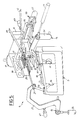
- reference numeral 1 generally denotes a cassette loading machine adapted to put into practice a cassette tape loading process providing for recovery of cassettes previously loaded with waste tape, in accordance with the present invention.
- the loading machine is arranged to operate on video cassettes of the VHS type and represents an innovation with respect to a loading machine being the object of Patent Application EP-89830147.8 in the name of the same Applicant.
- the loading machine 1 provides for the use of a cassette feeding unit consisting for example of a belt conveyor 2 on which a plurality of cassettes 3 being processed is disposed, said cassettes being sequentially conveyed to a front panel 4 of the machine.
- Delivery means 5 picks up the individual cassettes 5 from the conveyor belt 2 and sequentially engages them into a work station 6 at which each cassette undergoes the different operating steps for accomplishing the loading process.
- the delivery means 5 comprises for example an overturning device 7 that, at each operating cycle, picks up one cassette from the end of the belt conveyor 2 and disposes it vertically on first support elements carried by a transferring member 9.
- the transferring member 9 is movable along vertical guides (not shown) between one position in which it receives the cassette 3 engaged by the overturning device 7, to a second position in which said cassette is engaged in a pair of side guides 10 that, following a displacement towards the front panel 4, cause the cassette to be operatively engaged in the work station 6.
- the loading machine 1 is capable of carrying out the loading of empty audio or video cassettes (currently referred to as C-O and V-O cassettes) according to a conventional processing cycle aiming at winding a predetermined amount of use tape 12 into a cassette, which tape is continuously supplied from a pancake not shown.
- empty audio or video cassettes currently referred to as C-O and V-O cassettes
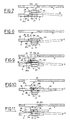
- Cassettes 3 reaching the work station 6 conventionally have a leader 13 (Fig. 3) a first portion 14 of which and a second portion 15 of which are respectively connected to first and second winding hubs, 16 and 17, rotatably housed in the cassette.
- the first and second portions, 14 and 15, of leader 13 form a single leader piece extending before a front opening 18 of the cassette 3.
- extraction means 19 arranged to suitably extract the leader 13 from the front opening 18 upon opening of a protection door 20 (Fig. 1), in a manner known per se and therefore not described.
- the extraction means 19 comprises first and second extractor elements 21, 22 engaged to the ends of a first and a second drive arm, 23, 24 respectively, and arranged to penetrate into corresponding access places 25 provided close to the front opening 18 of the cassette 3, as soon as said cassette is operatively engaged in the work station 6.
- Each extractor element 21, 22 is susceptible of being displaced, upon command of a main actuator 26, 27 acting on the corresponding drive arm 23, 24 between a rest position, in which it is introduced into the corresponding access space 25, and a maximum-extracted position in which, as shown in fig. 3, it is located at the outside of the front opening 18 of the cassette 3 to a predetermined distance therefrom.
- extractor elements 21, 22 are drivingly moved to the maximum-extracted position so that the leader 13 is extracted almost completely and laid down before the cassette front opening 18.
- the leader 13 is disposed on an engagement surface 28 exhibited by a first support block 29 and a first holding seat 30 disposed in alignment with the engagement surface 28 and exhibited by a second support block 31 disposed side by side with the first block 29.
- the engagement surface 28 and the first holding seat 30 facing the cassette front opening 18 are designed to hold the leader 13 by effect of a suction action produced through a plurality of holes 28a, 30a opening to said surface and seat.
- a first cutting means operates between the first and second blocks 29, 31 and it consists for example of a first cutter 32 operated by a respective actuator 33 that cuts the leader 13 according to a transverse direction, so as to sever it into a first portion 14 and a second portion 15.
- the first portion 14 will extend between the first support block 29 and the first winding hub 16, whereas the second portion 15 will extend between the second support block 31 and the second winding hub 17.
- the use tape 12 has a leading end 12a engaged to the second block 31 at a second holding seat 34 disposed parallelly in side by side relation with the first holding seat 30 and provided with respective suction holes 34a.
- suitable displacement means consisting of a displacement actuator 35 acting on a frame 36 carrying both blocks 29, 31 causes the simultaneous displacement of the blocks from a first operating condition in which the engagement surface 28 and holding seat 34 aligned therewith are facing the front opening 18, to a second operating condition in which said engagement surface and holding seat are operatively located in front of a splicing unit 37 mounted to the front panel 4 at a laterally offset position with respect to the cassette 3.
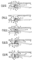
- the second support block 31 is moved relative to the first support block 29 so that the second holding seat 34 is brought into alignment with the engagement surface 28 of the first block and, as a consequence, the leading end 12a of the use tape to be loaded 12 is brought into alignment with the first leader portion 14 (Fig. 12).
- the splicing unit 37 by an arm means 37a movable towards the blocks 29, 31, applies a first adhesive joining tape 39 onto the ends of the first portion 14 of the leader and the leading part 12a of the tape, so as to join them consecutively.
- An abutment element 40 intermediate the blocks 29, 31 acts against the action of the arm means 37a in order to ensure an optimal adhesion of the adhesive tape to the leader 13 and use tape 12.
- This abutment element 40 is movable, upon command of a fluid-operated cylinder 41, apart from the leader 13 and tape 12 in order to make room for the first cutting member 32 when this cutting member must be operated.
- Blocks 29, 30 are then brought again to the first operating condition and, upon disengagement of the first portion 14 of the leader and the use tape to be loaded 12 by interrupting the suction effect on the engagement surface 28 and second holding seat 34, the first winding hub 16 is driven in rotation upon the action of a winding spindle 42 (Fig. 1) so as to cause the winding of a predetermined amount of use tape 12.
- the tape When the desired amount of use tape 12 has been wound onto the hub 16, the tape is engaged to the engagement surface 28 and the second holding seat 34 of blocks 29, 31 by a new displacement of the extractor element to the maximum-extracted position.
- the use tape 12 is then cut upon the action of the first cutter 32, and blocks 29, 31, upon returning of the extractor elements 21, 22 to the rest position, are brought to the second operating condition.
- the second block 31 Simultaneously with this operation, the second block 31 is moved again relative to the first block 29 so as to bring the second leader portion 15 into alignment with the trailing end 12b of the tape 12 held by the engagement surface 28.
- the splicing unit 37 is operated and it applies a second adhesive joining tape 43 (Fig. 15) to the trailing end 12b of the use tape and the second portion 15 of the leader.
- the cassette loading process is terminated by driving the first winding hub 16 in rotation again, in order to make the tape 12 and the second portion of leader 15 ultimately enter the cassette opening 18, said cassette being then released from the work station 6 and moved away by the transferring member 9.
- the leading end 12a of the use tape 12 to be loaded during a following processing cycle is still disposed on the second holding seat 34 of the second block 31.
- the above description refers to a conventional cassette loading cycle which can be executed by the loading machine 1 on C-O or V-O type cassettes.
- the loading machine 1 can also be used for recovering cassettes 3 previously loaded with waste tape 45.
- Cassettes 3 preloaded with waste tape 45 can be indiscriminately fed to the belt convevor 2 either in the absence of cassettes of the C-O or V-O type or in the presence of these cassettes, and in the latter case they can be alternated with said C-O or V-O type cassettes, even randomly.
- sensor means 44 is associated with the work station 6, being arranged to detect the presence or not of waste tape 45 within each cassette 3 being engaged in the work station.
- sensor means 44 substantially comprises at least one photoemitter 46 and one photoreceiver 47 located at the inside and outside respectively of the cassette 3 engaged in the work station 6.
- Photoemitter 46 on engagement of the cassette 3 in the work station 6, enters a housing 48 conventionally arranged in the cassette and lends itself to emit a light signal detectable by the first photoreceiver 47, through an aperture (not seen in the drawings) conventionally formed in the cassette.
- the light signal is subjected to cross the first portion 14 of the leader, at a length thereof extending from the first hub 16 to the front opening 18 of the cassette. Since, as is known, the leader 13 is made of transparent material, the light signal can reach the first photoreceiver 47.
- the second photoreceiver 49 lends itself to sense the light signal emitted from photoemitter 46 through a corresponding aperture 49a, in order to detect the presence of waste tape 45 wound onto the second hub 17, following the same modalities as previously described with reference to the first photoreceiver 47.
- a microprocessor drives the loading machine 1 in operation according to the processing cycle described above with reference to loading of C-O or V-O cassettes.
- the second portion 15 of the leader and a trailing section 45a of the waste tape 45 spliced to said leader portion are extracted from the front opening 18 and brought into engagement on the first holding seat 30 of the second support block 31 and the engagement surface 28 of the first support block 29, respectively, said holding seat and engagement surface being in mutual alignment.
- the splice between the waste tape 45 and second portion 15 of the leader, represented by the second adhesive joining tape 43 applied in the processing cycle previously executed on the same cassette is advantageously positioned on the first block 29, in such a manner that it is laterally offset towards the first block, with respect to the direction of operation of the first cutting member 32 (Figs. 4 and 7).
- This positioning of the splice is achieved by bringing the first extractor element 21 to the maximum-extracted position and simultaneously bringing the second extractor element 22 to a position intermediate the rest position and the corresponding maximum-extracted position.
- stopping of the second extractor element 22 to its intermediate position occurs by means of a first auxiliary actuator 50, that, when activated, interferes with the displacement of the second drive arm 24 in order to stop, against the action of the corresponding main actuator 27, the displacement of the second extractor element to its maximum-extracted position.
- the second portion 15 of the leader is cut and completely cleared of the second adhesive joining tape 43, which is kept attached to the trailing section 45a of the waste tape 45 held by the engagement surface 28 of the first block 29.
- connection of the trailing section 45a of the waste tape 45 with the auxiliary threading means 51 is carried out by interconnecting means 52 providing for the presence of a third holding seat 53 on the second block 31, disposed parallelly in side by side relation with the second holding seat 34.
- the third holding seat 53 is designed to hold an end portion 54a of a tape length 54 discarded in a previous processing cycle, still by effect of suction produced through holes 53a opening to said third holding seat.
- This tape length 54 has its foremost portion 54b
- This tape length 54 has its foremost portion 54b arranged in engagement on a holding element 55 being part of the auxiliary threading means 51.
- the holding element 55 substantially comprises a fixed block exhibiting a support surface on which, in this case too as a result of a suction effect, the foremost portion 54b of the tape length 54 is retained
- the second block 31 After carrying out the cut of the second portion 15 of the leader and upon return of the extractor elements 21, 22 to the rest position, the second block 31 is moved with respect to the first block 29 so that the third holding seat 53 carrying the end portion 54a of length 54 is disposed in alignment with the engagement surface 28 carrying the trailing section 45a of the waste tape 45 (Fig. 8).
- said drive means 38 should be comprised of a first movement actuator 56 the rod 56a of which (only partly shown in the drawings) acts on the second block 31 so as to move it from a first position in which the first holding seat 30 is in alignment with the engagement surface 28 to a third position in which the third holding seat 53 is in alignment with the engagement surface itself.
- a second movement actuator 57 is fixed in succession to the first actuator 56 and, when activated, said second actuator acts by its rod 57a against the rod 56a of the first actuator 56, in order to restrain the stroke of the second block 31 towards the third position, stopping it to a second position in which the alignment of the second holding seat 34 with the engagement surface 28 is achieved.
- the first and second blocks 29, 31 are brought to the second operating position and the splicing unit 37 carries out the splicing between the trailing section 45a of the waste tape 45 and the first end portion 54a of the tape length 54, by application of a third adhesive joining tape 58 (Fig. 9).
- Blocks 20, 31 are brought back to the first operating condition and, upon disengagement of the waste tape 45 and tape length 54 from said blocks by interruption of said suction effect, a step providing the extraction of the waste tape 45 from the cassette 3 is initiated upon the action of the auxiliary threading means 51.
- the auxiliary threading means 51 comprises a gripper element 59 controlled by a fluid-operated displacement cylinder 60, said gripper element being movable between a first position in which it is disposed close to the holding element 55 for picking up, as a result of a suction effect, the foremost portion 54b of length 54, and a second position in which it is moved away from the holding element 55 so that it can extend the tape length 54 in a predetermined direction.
- a winding fork 61 operates on the length portion 54 extending between the holding element 55 and gripper element 59 moved to the second position.
- Said fork in a manner known per se, is movable perpendicularly to the movement direction of the gripper element 59 between a rest position in which it does not interfere with the movement of the gripper element, and an operating position in which, as shown in Fig. 6, it operatively engages the tape length 54 at a diametrical slit 62 provided in the fork itself.
- the orientation of the diametrical slit 62 is suitably fixed by a unidirectional ratchet pawl 63 capable of interferring with an abutment notch 64 carried on the periphery of fork 61, when said fork is driven in rotation by a motor 61a in a predetermined direction, that is clockwise with reference to Fig. 6.
- the fork 61 is driven in rotation in a direction opposite to that causing the interference of the ratchet pawl 63 with the abutment notch 64 so that the fork carries out the threading and winding upon itself of the tape length 54 and waste tape 45 as it is drawn from the first hub 16.
- a count wheel 65 operatively engaged on the path of the tape length 54 and waste tape 45 being unwound is driven in rotation at an angular speed proportionate to the movement speed of the waste tape.
- the difference between the angular speeds of the count wheel 65 and first hub 16 detected bv appropriate sensors not described as known per se reaches a predetermined value, the rotational speed of the winding fork 61 is reduced in order to prevent the leader 13 from being pulled away from the first hub 16 or at all events damaged, at the end of the waste tape 45 unwinding.
- the first extractor element 21 is moved from its rest position in order to cause the engagement of the first leader portion 14 and the leading section 45b of the waste tape 45 on the engagement surface 28 of the first block 29 and the third holding seat 53 of the second block 31, respectively.
- a portion of the waste tape 45 is required to be unwound from the winding fork 61, said fork being therefore obliged to rotate in the opposite direction with respect to the winding direction.
- a release actuator 66 acting on the unidirectional ratchet pawl 63 and moving it to a position in which it does not interfere with the abutment notch 64 arranged in the fork.
- a second auxiliary actuator 67 (Fig. 5) is operated which is designed to act on the first drive arm 23 for stopping, against the action of the corresponding main actuator 26, the movement of the extractor element to a position intermediate the maximum-extracted position and rest position.
- the first cutting member 32 is operated and it cuts the first portion 14 of the leader, completely separating it from the first adesive tape 39, which is kept attached to the leading section 45b of the waste tape 45.
- the second block 31 is disposed to its second work position so that the second holding seat 34 carrying the leading end 12a of the new use tape 12 to be loaded into the cassette 3 is brought into alignment with the engagement surface 28 of the first block 29.
- the loading process goes on following the same modalities as known processes for loading C-O or V-O cassettes starting from the step of splicing the first portion of leader 14 to the leading end 12a of the use tape 12 to be wound, the operating sequence being that shown in Figs. 11 to 16.
- waste tape 45 wound on the fork 61 is cut by an auxiliary cutter 68 at the holding element 55, giving thereby origin to a new tape length 54 extending between the third holding seat 53 of the second block 31 and the holding element itself.
- the waste tape roll 69 formed on fork 61 is dropped in a manner known per se, due to the backward movement of the fork to the rest position, then the gripper element 59 can be brought back to its first work position at the holding element 55.
- the invention achieves important advantages.
Landscapes
- Replacement Of Web Rolls (AREA)
- Input Circuits Of Receivers And Coupling Of Receivers And Audio Equipment (AREA)
- Auxiliary Devices For And Details Of Packaging Control (AREA)
Claims (24)
- Ladeprozess eines Kassettenbandes zur Wiederverwertung von vorher mit Abfallband gefüllten Kassetten, umfassend die Arbeitsschritte:Ergreifen in einer Arbeitsstation (6) einer ein Abfallband (45) enthaltenden Kassette (3) über Klebebänder (39, 43), die jeweils an einem Kopfende (45b) und einem Schwanzende (45a) des Abfallbandes, jeweils an einem Kopfabschnitt und an einem Schwanzabschnitt (14, 15) eines Leaders (13) angebracht sind, die an einem ersten und an einem zweiten, in der Kassette (3) aufgenommenen Wickelkern (16, 17) angreifen;Auszug aus einer Stirnöffnung (18) der Kassette (3) des zweiten Abschnittes (15) des Leaders zusammen mit dem Schwanzende (45a) des auf dem ersten Kern (16) der Kassette (3) aufgewickelten Abfallbandes (45);Abschneiden des zweiten Abschnittes (15) des Leaders, um ihn vom Schwanzabschnitt (45a) des Abfallbandes (45) abzutrennen;Verbindung des Schwanzendes (45a) des Abfallbandes (45) mit außen auf die Kassette (3) wirkenden Hilfsmitnahmemitteln (51);Abwicklung des Abfallbandes (45) vom ersten Kern (16) über Hilfsmitnahmemittel (51), bis zum Auszug aus der Stirnöffnung (18) der Kassette (3), des ersten Abschnittes (14) des Leaders (13) zusammen mit dem Kopfende (45b) des Abfallbandes (45);Abschneiden des ersten Abschnittes (14) des Leaders (13) um ihn von dem Kopfende (45b) des aus der Kassette (3) ausgezogenen Abfallbandes zu trennen;Ausrichtung des ersten Abschnittes (14) des Leaders (13) mit dem Kopfbeginn (12a) eines in der Kassette (3) zu ladenden Magnetbandes (12);Verklebung des Kopfbeginnes (12a) mit dem ersten Abschnitt (14) des Leaders;Aufwickeln auf dem ersten Kern (16) einer gewünschten Menge von zu ladendem Magnetband (12);Abschneiden des in der Kassette (3) geladenen Magnetbandes (12) um davon ein Schwanzbeginn (12b) vom Kopfbeginn (12a) des im nachfolgenden Arbeitsgang zu ladenden Magnetbandes abzutrennen;Ausrichtung des Kopfbeginnes (12a) des in der Kassette (3) geladenen Magnetbandes (12) mit dem zweiten Abschnitt (15) des Leaders (13);Verklebung des Schwanzbeginnes (12a) des geladenen Magnetbandes (12) mit dem zweiten Abschnitt (15) des Leaders;Aufwickeln in der Kassette (3) des geladenen Bandes (12) und des zweiten Abschnittes (15) des Leaders (13), die miteinander verklebt wurden, und Auswerfen der Kassette (3) aus der Arbeitsstation (6).
- Prozess nach Anspruch 1, dadurch gekennzeichnet, daß er die folgenden, weiteren Arbeitsschritte umfaßt:Ergreifen, zusammen mit deren Auszugsarbeitsschrittes aus der Kassette, des Schwanzendes (45a) des Abfallbandes (45) und des zweiten Abschnittes (15) des Leaders (13) jeweils an einer Angriffsfläche (28) eines ersten Halterungsklotzes (29) und an einer ersten Rückhalteaufnahme (30), die von einem zweiten Halterungsklotz (31) getragen und mit der Angriffsfläche (28) ausgerichtet ist, wobei der erste und der zweite Klotz (29, 31) in gegenüberliegenden Stellungen gegenüber der Richtung angeordnet sind, gemäß der die Schneidschritte durchgeführt werden,gegenseitige Verstellung der Klötze (29, 31) nach der Durchführung des Abtrennens des Schwanzabschnittes (15) des Leaders (13), um das Abfallband (15) mit einem Endabschnitt (54a) eines in einem vorangehenden Arbeitsgang verworfenen Bandstückes (54) in Ausrichtung zu bringen, das von einer dritten durch den zweiten Klotz (31) getragenen Rückhalteaufnahme (53) getragen wird und wirksam mit den Hilfsmitnahmemitteln (51) verbunden ist;Verklebung des Abfallbandes (45) mit dem zuvor verworfenen Bandstück (54), um den Arbeitsschritt der Verbindung des Abfallbandes (45) mit dem Hilfsmitnahmemitteln (51) durchzuführen.
- Prozess nach Anspruch 2, dadurch gekennzeichnet, daß er überdies den Schritt der Freigabe des Abfallbandes (45) und des verworfenen Bandstückes (54) von den Halterungsklötzen (29, 31) umfaßt, bevor der Schritt der Abwicklung des Abfallbandes (45) verwirklicht wird.
- Prozess nach Anspruch 2, dadurch gekennzeichnet, daß er überdies die Arbeitsschritte umfaßt:Ergreifen des ersten Abschnittes (14) des Leaders (13) und des Kopfendes (45b) des abgewickelten Abfallbandes (45) jeweils auf der Angriffsfläche (28) des ersten Klotzes (29) und auf der dritten Rückhalteaufnahme (53) des zweiten Klotzes (31), bevor der Schnitt des ersten Abschnittes (14) des Leaders (13) durchgeführt wird;gegenseitige Verstellung des ersten und des zweiten Klotzes (29, 31), um den ersten Abschnitt (14) des Leaders (13) mit dem Kopfbeginn (12a) des zu ladenden Magnetbandes (12) in Ausrichtung zu bringen, das von einer vom zweiten Klotz (31) aufgewiesenen zweiten Rückhalteaufnahme (34) getragen wird, bevor der Verklebungsschritt zwischen dem zu ladenden Magnetband (12) und dem ersten Abschnitt (14) des Leaders (13) durchgeführt wird.
- Prozess nach Anspruch 2, dadurch gekennzeichnet, daß zusammen mit dem Schritt des Ergreifens des Schwanzendes (45a) des Abfallbandes (45) und des zweiten Abschnittes (15) des Leaders (13) jeweils an den Klötzen (29, 31), ein zweites am Abfallband (45) und am zweiten Abschnitt (15) des Leaders angebrachtes Klebeband (43) in einer zum ersten Klotz (29) gegenüber der Richtubg seitlich versetzten Stellung angeordnet wird, gemäß welcher Richtung die Schneidschritte durchgeführt werden, wodurch dieses zweite Klebeband (43) am Schwanzende (45a) des Abfallbandes (45) zufolge des Schneidschrittes des zweiten Abschnittes (15) des Leaders (13) in Eingriff bleibt.
- Prozess nach Anspruch 4, dadurch gekennzeichnet, daß zusammen mit dem Schritt des Ergreifens des ersten Abschnittes (14) des Leaders (13) und des Kopfendes (45b) des Abfallbandes (45) jeweils an den Klötzen (29, 31) ein erstes am Kopfende des Abfallbandes (45) und am ersten Abschnitt des Leaders (13) angewandtes Klebeband (39) in einer zum zweiten Klotz (31) gegenüber der Richtung seitlich versetzter Stellung angeordnet wird, gemäß welcher Richtung die Schneidschritte durchgeführt werden, wodurch dieses erste Klebeband (39) am Kopfende (45b) des Abfallbandes (45) zufolge des Schneidschrittes des Kopfabschnittes (14) des Leaders (13) in Eingriff bleibt.
- Prozess nach Anspruch 1, dadurch gekennzeichnet, daß er überdies den Schritt umfaßt, die Anwesenheit vom Abfallband (45) in der Kassette (3) in der Ladestellung an dem ersten und/oder zweiten Kern (16, 17) festzustellen.
- Prozess nach Anspruch 7, dadurch gekennzeichnet, daß er überdies den Arbeitsschritt umfaßt, das gesamte Abfallband (45) in der Kassette (3) am ersten Kern (16) aufzuwickeln, in Antwort auf die Feststellung des Abfallbandes (45) am zweiten Kern (17).
- Automatische Bandkassettenlademaschine, umfassend:mindestens eine Arbeitsstation (6), die wirksam eine in Bearbeitung befindliche Kassette (3) ergreift, die mindestens einen Leader (13) mit einem ersten Abschnitt (14) und einem zweiten Abschnitt (15) enthält, die jeweils an einem ersten und an einem zweiten Wickelkern (16, 17) angreifen, die in der Kassette selbst angeordnet sind;Auszugsmittel (19), um den Leader (13) aus einer Stirnöffnung (18) der Kassette (3) auszuziehen;eine Angriffsfläche (28), um den ersten Abschnitt (14) des aus der Kassette selbst ausgezogenen Leaders (13) ergreifend aufzunehmen;eine erste und eine zweite Rückhalteaufnahme (30, 34), die jeweils den zweiten (15) des aus der Kassette (3) ausgezogenen Leaders (13) und einen von einem in der Kassette (3) zu ladenden Magnetband aufgewiesenen Kopfbeginn (12a) ergreifend aufzunehmen bereitgestellt sind;Verstellmittel (38), um die erste und die zweite Rückhalteaufnahme (30, 34), wahlweise mit der Angriffsfläche (28) in Ausrichtung zu bringen;erste Schneidmittel (32, 33), um den Kopfabschnitt und den Schwanzabschnitt (14, 15) des aus der Stirnöffnung (18) ausgezogenen Leaders (13) voneinander zu trennen, sowie um das in der Kassette (3) geladenen Band (12) abzschneiden;Klebemittel (37), um den ersten Abschnitt (14) des Leaders (13) mit dem Kopfbeginn (12a) des zu ladenden Bandes (12) sowie den zweiten Abschnitt (15) des Leaders (13) mit dem Schwanzbeginn (12b) des in der Kassetten gelandenen Bandes (12) zu verkleben;
wobei diese Maschine dadurch gekennzeichnet ist, daß sie überdies umfaßt:Hilfsmitnahmemittel (51), um ein am ersten Kern der Kassette (3) aufgewickeltes Abfallband (45) aus der Kassette selbst auszuziehen; undVerbindungsmittel (52), um mit den Hilfmitnahmemitteln (51) ein Schwanzende (45a), das vorher vom zweiten Abschnitt (15) des Leaders (13) getrennt wurde, über die Schneidmittel (32, 33) wirksam zu verbinden,
wobei die Schneidmittel (32, 33) überdies dazu bereitgestellt sind, um die Kopf- und Schwanzabschnitte des Leaders (13) in der Nähe der jeweiligen Enden (45a, 45b) des Abfallbandes (45) abzuschneiden. - Maschine nach Anspruch 9, dadurch gekennzeichnet, daß die Verbindungsmittel (52) mindestens eine dritte Rückhalteaufnahme (35) umfassen, die dazu bereitgestellt ist, einen Endabschnitt (54a) eines Abfallbandstückes (54) zurückzuhalten, das einen Anfangsabschnitt (54b) mit den Mitnahmemitteln (51) in Eingriff besitzt.
- Maschine nach Anspruch 9, dadurch gekennzeichnet, daß die Angriffsfläche (28) an einem ersten Halterungsklotz (29) angeordnet ist.
- Maschine nach Anspruch 9, dadurch gekennzeichnet, daß die erste und die zweite Rückhalteaufnahme (30, 34) am zweiten Klotz (31) angeordnet sind.
- Maschine nach Anspruch 9, dadurch gekennzeichnet, daß die Verbindungsmittel (52) mindestens eine dritte Rückhalteaufnahme (53) umfassen, die parallel gegenüber der ersten und der zweiten, im zweiten Klotz (31) gebildeten Rückhalteaufnahmen (30, 34) parallel ausgerichtet angeordnet sind, wobei die dritte Rückhalteaufnahme (53) in der Lage ist, mit der vom ersten Klotz (29) getragenen Angriffsfläche (28) durch Einwirkung der Verstellmittel (38) ausgerichtet zu werden, um die Verklebung des Schwanzendes (45a) des Abfallbandes (45) mit dem Endabschnitt (54a) des Bandstückes (54) durch Einwirkung der Klebemittel (37) zu erlauben.
- Maschine nach Anspruch 13, dadurch gekennzeichnet, daß die dritte Rückhalteaufnahme (53) unmittelbar am zweiten Klotz (31) in einer gegenüber der zweiten Rückhalteaufnahme (34) angereihten Stellung ausgearbeitet ist.
- Maschine nach Anspruch 9, dadurch gekennzeichnet, daß die Auszugsmittel erste und zweite Auszugselemente (21, 22) erfassen, die jeweils zwischen einer ersten, einer zweiten und einer dritten Stellung beweglich sind.
- Maschine nach Anspruch 15, dadurch gekennzeichnet, daß die erste Stellung der Auszugsmittel (21, 22) eine Ruhestellung ist, in der die Auszugsmittel (21, 22) in einer Zugangsaussparung (25) angeordnet sind, die in einer Kassette (3) gebildet ist, die in der Ladestation (6) in Eingriff steht, und dadurch, daß die zweite Stellung der Auszugselemente (21, 22) eine Zwischenstellung ist, die dem aus einer in der Ladestation (6) in Eingriff stehenden Kassette (3) ausgezogenen Band erlaubt, seitlich gegenüber den ersten, zweiten, dritten und vierten Bandrückhaltemitteln (28, 30, 34, 53) verschoben zu werden.
- Maschine nach Anspruch 16, dadurch gekennzeichnet, daß die Auszugsmittel (19) überdies einen Hauptzylinder (26, 27) umfassen, um die ersten und die zweiten Auszugsmittel (21, 22) zwischen der Ruhestellung und einer höchsten Auszugsstellung zu bewegen, in der er außen von der Stirnöffnung (18) der Kassette entfernt ist, wobei jedem Auszugselement (21, 22) mindestens ein Hilfszylinder (50, 67) zugeordnet ist, der aktivierbar ist, um den Hube des Auszugselementes selbst in Richtung der höchsten Auszugsstellung zu blockieren, indem er in dieser Zwischenstellung angehalten wird.
- Maschine nach Anspruch 9, dadurch gekennzeichnet, daß daß die Hilfsmitnahmemittel (51) ein bewegliches Greifelement (59) umfassen, um den Anfangsabschnitt (54b) eines Bandstückes (54) zurückzuhalten und ihn in eine wirksame Ergreifung mit einer Bandwickelvorrichtung (61) zu verstellen.
- Maschine nach Anspruch 18, dadurch gekennzeichnet, daß die Hilfsmitnahmemittel (51) umfassen:ein Rückhalteelement (55), das dazu bereitgestellt ist, den Anfangsabschnitt (54b) des Abfallbandstückes (54) zurückzuhalten;wobei das Greifelement (59) zwischen einer ersten Stellung, in der es im Bereich des Rückhalteelementes (55) zur Entnahme des Anfangsabschnittes (54b) des Bandstückes (54) angeordnet ist, und einer zweiten Stellung beweglich ist, in der es vom Rückhalteelement (55) entfernt ist, um das Bandstück (54) gemäß einer vorbestimmten Richtung auszubreiten; wobei die Bandwickelvorrichtung eine Wickelgabel (61) umfaßt, die zwischen einer Ruhestellung, in der sie mit der Verstellung des Greifelementes (59) nicht zusammenwirkt, und einer Arbeitsstellung beweglich ist, in der sie das durch das Greifelement selbst ausgebreitete Bandstück (54) ergreift, wobei die Gabel (61) drehbeweglich ist, um auf sich selbst das Bandstück (54) und das zuerst mit dem Bandstück selbst verklebten Abfallband (54) mitzunehmen und aufzuwickeln.
- Maschine nach Anspruch 9, dadurch gekennzeichnet, daß sie überdies Fühlermittel (44) umfaßt, um die Anwesenheit des Abfallbandes (45) der in der Arbeitsstation (6) in Eingriff stehenden Kassette (3) festzustellen.
- Maschine nach Anspruch 20, dadurch gekennzeichnet, daß die Fühlermittel (44) mindestens einen Fotoemitter (46) und mindestens einen ersten Fotoempfänger (47) umfassen, die jeweils innerhalb und außerhalb der in der Arbeitsstation (6) in Eingriff stehenden Kassette (3) angeordnet sind, wobei der Fotoempfänger (47) dazu bereitgestellt ist, die Anwesenheit des am ersten Kern (16) aufgewickelten Abfallbandes (45) zufolge der Unterbrechung seitens des Bandes selbst eines vom Fotoemitter (46) abgegebenen Lichtsignals festzustellen, wobei der Leader (13) aus durchsichtigem Material besteht.
- Maschine nach Anspruch 21, dadurch gekennzeichnet, daß sie überdies mindestens einen zweiten Fotoempfänger (49) umfaßt, der außerhalb der Kassette (3) in einer gegenüber dem ersten Fotoempfänger (47) abgewandten Stellung angeordnet und dazu bereitgestellt ist, die Anwesenheit des am zweiten Kern (17) aufgewickelten Abfallbandes (45) zufolge der Unterbrechung des vom Fotoemitter (46) ausgesendeten Lichtsignals seitens des Bandes selbst festzustellen.
- Maschine nach Anspruch 20, dadurch gekennzeichnet, daß die Fühlermittel (44) in der Lage sind festzustellen, ob das Abfallmagnetband (45) auf einem der Kerne (16, 17) oder an beiden Kernen einer in der Ladestation (6) in Eingriff stehenden Kassette (3) aufgewickelt ist.
- Maschine nach Anspruch 14, dadurch gekennzeichnet, daß die ersten Verstellmittel (38) umfassen:einen ersten auf den zweiten Klotz (31) wirkenden Zylinder (56), um ihn zwischen einer ersten Stellung, in der die erste Rückhalteaufnahme (30) mit der Angriffsfläche (28) des ersten Klotzes (29) ausgerichtet ist, und einer zweiten Stellung zu verstellen, in der die dritte Rückhalteaufnahme (53) mit der Angriffsfläche (28) ausgerichtet ist, undeinen zweiten Zylinder (57) der gegenüber dem ersten Zylinder (56) festliegt und aktivierbar ist, um den Hub des zweiten Klotzes (31) in Richtung der dritten Stellung zu begrenzen und ihn in einer zweiten Stellung zu blockieren, in der die zweite Rückhalteaufnahme (34) mit der Angriffsfläche (28) ausgerichtet ist.
Applications Claiming Priority (2)
| Application Number | Priority Date | Filing Date | Title |
|---|---|---|---|
| ITMI922505A IT1256050B (it) | 1992-10-30 | 1992-10-30 | Procedimento per confezionare cassette a nastro recuperando cassette precaricate con nastro magnetico di scarto,e macchina confezionatrice per l'attuazione di tale procedimento. |
| ITMI922505 | 1992-10-30 |
Publications (2)
| Publication Number | Publication Date |
|---|---|
| EP0594923A1 EP0594923A1 (de) | 1994-05-04 |
| EP0594923B1 true EP0594923B1 (de) | 1998-09-23 |
Family
ID=11364210
Family Applications (1)
| Application Number | Title | Priority Date | Filing Date |
|---|---|---|---|
| EP92830658A Expired - Lifetime EP0594923B1 (de) | 1992-10-30 | 1992-12-07 | Ladeprozess eines Kassettenbandes zur Wiederverwertung von vorher mit Abfallband gefüllten Kassetten und Lademaschine zur Verwirklichung des Prozesses |
Country Status (6)
| Country | Link |
|---|---|
| US (2) | US5806784A (de) |
| EP (1) | EP0594923B1 (de) |
| AT (1) | ATE171559T1 (de) |
| DE (1) | DE69227113T2 (de) |
| ES (1) | ES2121839T3 (de) |
| IT (1) | IT1256050B (de) |
Families Citing this family (2)
| Publication number | Priority date | Publication date | Assignee | Title |
|---|---|---|---|---|
| DE19644049A1 (de) * | 1995-11-11 | 1997-05-28 | Basf Magnetics Gmbh | Verfahren und Vorrichtung zum Demontieren von Bandkassetten |
| US7733598B1 (en) * | 2006-04-24 | 2010-06-08 | Oracle America, Inc. | Tape cartridge and tape drive system with internal and external tape guides |
Family Cites Families (7)
| Publication number | Priority date | Publication date | Assignee | Title |
|---|---|---|---|---|
| US3737358A (en) * | 1971-05-27 | 1973-06-05 | King Instrument Corp | Splicer head assembly for use in splicing tape to leaders |
| US4497454A (en) * | 1983-03-11 | 1985-02-05 | King Instrument Corporation | Tape loading machine |
| GB8518748D0 (en) * | 1985-07-24 | 1985-08-29 | Tape Automation Ltd | Splicing & loading tape into cassettes |
| JPS62106377U (de) * | 1985-12-23 | 1987-07-07 | ||
| JPS62180573A (ja) * | 1986-02-03 | 1987-08-07 | Fuji Photo Film Co Ltd | テ−プ欠陥除去方法 |
| IT1202663B (it) * | 1987-03-10 | 1989-02-09 | Luciano Perego | Apparecchiatura e procedimento per l'avvolgimento di nastri in cassette,particolarmente per nastri magnetici |
| JPH02250198A (ja) * | 1989-03-24 | 1990-10-05 | Tdk Corp | テープカセット自動販売機 |
-
1992
- 1992-10-30 IT ITMI922505A patent/IT1256050B/it active IP Right Grant
- 1992-12-07 AT AT92830658T patent/ATE171559T1/de not_active IP Right Cessation
- 1992-12-07 EP EP92830658A patent/EP0594923B1/de not_active Expired - Lifetime
- 1992-12-07 DE DE69227113T patent/DE69227113T2/de not_active Expired - Fee Related
- 1992-12-07 ES ES92830658T patent/ES2121839T3/es not_active Expired - Lifetime
-
1997
- 1997-04-28 US US08/847,891 patent/US5806784A/en not_active Expired - Fee Related
-
1998
- 1998-07-02 US US09/110,426 patent/US5927641A/en not_active Expired - Fee Related
Also Published As
| Publication number | Publication date |
|---|---|
| ITMI922505A0 (it) | 1992-10-30 |
| ES2121839T3 (es) | 1998-12-16 |
| DE69227113T2 (de) | 1999-02-18 |
| DE69227113D1 (de) | 1998-10-29 |
| EP0594923A1 (de) | 1994-05-04 |
| US5806784A (en) | 1998-09-15 |
| ITMI922505A1 (it) | 1994-04-30 |
| US5927641A (en) | 1999-07-27 |
| ATE171559T1 (de) | 1998-10-15 |
| IT1256050B (it) | 1995-11-21 |
Similar Documents
| Publication | Publication Date | Title |
|---|---|---|
| US4228579A (en) | Method and apparatus for winding a strip of film and for inserting it in a cassette | |
| EP0594923B1 (de) | Ladeprozess eines Kassettenbandes zur Wiederverwertung von vorher mit Abfallband gefüllten Kassetten und Lademaschine zur Verwirklichung des Prozesses | |
| US4979690A (en) | Apparatus and method for winding up magnetic tapes in cassettes | |
| EP0770548B1 (de) | Vorrichtung zum Bündeln von Bogen und mit derselben versehene Bogenbehandlungsvorrichtung | |
| US6167933B1 (en) | Apparatus and method for automatically inserting markers into books | |
| CN106586679A (zh) | 一种全自动载带缠绕机 | |
| JPH0342458B2 (de) | ||
| EP0472801B1 (de) | Verfahren und Vorrichtung zum Auffinden eines Endes eines Magnetbands, das auf einer Spule in einem automatischen Kassettenladegerät aufgewickelt ist | |
| JP2000114778A (ja) | テープフィーダおよびテープ送り方法 | |
| JPS62157162A (ja) | 印刷機の全自動給紙方法および装置 | |
| EP0376895B1 (de) | Kontinuierlicher Zufuhr- und Entladefluss durch ein Kassettenladegerät und System dafür | |
| EP0471133B1 (de) | Vorrichtung zum Aufnehmen und Zuführen in einem vorbestimmten Weg eines auf einer Spule aufgewickelten Magnetbandes in einem automatischen Kassettenladegerät | |
| JPH0583994B2 (de) | ||
| KR100187462B1 (ko) | 필름자동현상장치 | |
| CA2061294C (en) | Process and apparatus for finding one end of tape wound onto a reel | |
| US20230290211A1 (en) | Cash dispenser unit and automatic recovery method of the same | |
| US5340048A (en) | Method and apparatus for cutting and splicing tape in automatic cassette loading machines | |
| JP3818306B2 (ja) | 感光性フィルムマガジンの製造方法 | |
| JP3166479B2 (ja) | 自動スプライサー | |
| JP3690508B2 (ja) | 感光性フィルムマガジン製造装置 | |
| JP3809652B2 (ja) | 感光性フィルムマガジンの製造方法 | |
| JPS6265855A (ja) | 紙葉類取扱い装置 | |
| JPH0429151B2 (de) | ||
| JPH08192819A (ja) | 紙葉類処理装置 | |
| JPS5944719B2 (ja) | テ−プカセツト組立装置における供給用テ−プリ−ルの自動交換装置 |
Legal Events
| Date | Code | Title | Description |
|---|---|---|---|
| PUAI | Public reference made under article 153(3) epc to a published international application that has entered the european phase |
Free format text: ORIGINAL CODE: 0009012 |
|
| 17P | Request for examination filed |
Effective date: 19930601 |
|
| AK | Designated contracting states |
Kind code of ref document: A1 Designated state(s): AT BE CH DE DK ES FR GB GR IE LI LU MC NL PT SE |
|
| 17Q | First examination report despatched |
Effective date: 19970314 |
|
| GRAG | Despatch of communication of intention to grant |
Free format text: ORIGINAL CODE: EPIDOS AGRA |
|
| GRAG | Despatch of communication of intention to grant |
Free format text: ORIGINAL CODE: EPIDOS AGRA |
|
| GRAH | Despatch of communication of intention to grant a patent |
Free format text: ORIGINAL CODE: EPIDOS IGRA |
|
| GRAH | Despatch of communication of intention to grant a patent |
Free format text: ORIGINAL CODE: EPIDOS IGRA |
|
| GRAH | Despatch of communication of intention to grant a patent |
Free format text: ORIGINAL CODE: EPIDOS IGRA |
|
| GRAA | (expected) grant |
Free format text: ORIGINAL CODE: 0009210 |
|
| AK | Designated contracting states |
Kind code of ref document: B1 Designated state(s): AT BE CH DE DK ES FR GB GR IE LI LU MC NL PT SE |
|
| PG25 | Lapsed in a contracting state [announced via postgrant information from national office to epo] |
Ref country code: LI Free format text: LAPSE BECAUSE OF FAILURE TO SUBMIT A TRANSLATION OF THE DESCRIPTION OR TO PAY THE FEE WITHIN THE PRESCRIBED TIME-LIMIT Effective date: 19980923 Ref country code: GR Free format text: LAPSE BECAUSE OF NON-PAYMENT OF DUE FEES Effective date: 19980923 Ref country code: CH Free format text: LAPSE BECAUSE OF FAILURE TO SUBMIT A TRANSLATION OF THE DESCRIPTION OR TO PAY THE FEE WITHIN THE PRESCRIBED TIME-LIMIT Effective date: 19980923 Ref country code: BE Free format text: LAPSE BECAUSE OF FAILURE TO SUBMIT A TRANSLATION OF THE DESCRIPTION OR TO PAY THE FEE WITHIN THE PRESCRIBED TIME-LIMIT Effective date: 19980923 Ref country code: AT Free format text: LAPSE BECAUSE OF FAILURE TO SUBMIT A TRANSLATION OF THE DESCRIPTION OR TO PAY THE FEE WITHIN THE PRESCRIBED TIME-LIMIT Effective date: 19980923 |
|
| REF | Corresponds to: |
Ref document number: 171559 Country of ref document: AT Date of ref document: 19981015 Kind code of ref document: T |
|
| REG | Reference to a national code |
Ref country code: CH Ref legal event code: EP |
|
| REF | Corresponds to: |
Ref document number: 69227113 Country of ref document: DE Date of ref document: 19981029 |
|
| ET | Fr: translation filed | ||
| PG25 | Lapsed in a contracting state [announced via postgrant information from national office to epo] |
Ref country code: LU Free format text: LAPSE BECAUSE OF NON-PAYMENT OF DUE FEES Effective date: 19981207 Ref country code: IE Free format text: LAPSE BECAUSE OF NON-PAYMENT OF DUE FEES Effective date: 19981207 |
|
| REG | Reference to a national code |
Ref country code: IE Ref legal event code: FG4D Ref country code: ES Ref legal event code: FG2A Ref document number: 2121839 Country of ref document: ES Kind code of ref document: T3 |
|
| PG25 | Lapsed in a contracting state [announced via postgrant information from national office to epo] |
Ref country code: SE Free format text: LAPSE BECAUSE OF FAILURE TO SUBMIT A TRANSLATION OF THE DESCRIPTION OR TO PAY THE FEE WITHIN THE PRESCRIBED TIME-LIMIT Effective date: 19981223 Ref country code: PT Free format text: LAPSE BECAUSE OF FAILURE TO SUBMIT A TRANSLATION OF THE DESCRIPTION OR TO PAY THE FEE WITHIN THE PRESCRIBED TIME-LIMIT Effective date: 19981223 Ref country code: DK Free format text: LAPSE BECAUSE OF FAILURE TO SUBMIT A TRANSLATION OF THE DESCRIPTION OR TO PAY THE FEE WITHIN THE PRESCRIBED TIME-LIMIT Effective date: 19981223 |
|
| REG | Reference to a national code |
Ref country code: CH Ref legal event code: PL |
|
| PG25 | Lapsed in a contracting state [announced via postgrant information from national office to epo] |
Ref country code: MC Free format text: LAPSE BECAUSE OF NON-PAYMENT OF DUE FEES Effective date: 19990630 |
|
| PLBE | No opposition filed within time limit |
Free format text: ORIGINAL CODE: 0009261 |
|
| 26N | No opposition filed | ||
| REG | Reference to a national code |
Ref country code: IE Ref legal event code: MM4A |
|
| PGFP | Annual fee paid to national office [announced via postgrant information from national office to epo] |
Ref country code: GB Payment date: 20001206 Year of fee payment: 9 |
|
| PGFP | Annual fee paid to national office [announced via postgrant information from national office to epo] |
Ref country code: FR Payment date: 20001212 Year of fee payment: 9 |
|
| PGFP | Annual fee paid to national office [announced via postgrant information from national office to epo] |
Ref country code: ES Payment date: 20001220 Year of fee payment: 9 |
|
| PG25 | Lapsed in a contracting state [announced via postgrant information from national office to epo] |
Ref country code: GB Free format text: LAPSE BECAUSE OF NON-PAYMENT OF DUE FEES Effective date: 20011207 |
|
| PGFP | Annual fee paid to national office [announced via postgrant information from national office to epo] |
Ref country code: NL Payment date: 20011228 Year of fee payment: 10 |
|
| REG | Reference to a national code |
Ref country code: GB Ref legal event code: IF02 |
|
| GBPC | Gb: european patent ceased through non-payment of renewal fee |
Effective date: 20011207 |
|
| PG25 | Lapsed in a contracting state [announced via postgrant information from national office to epo] |
Ref country code: FR Free format text: LAPSE BECAUSE OF NON-PAYMENT OF DUE FEES Effective date: 20020830 |
|
| REG | Reference to a national code |
Ref country code: FR Ref legal event code: ST |
|
| PG25 | Lapsed in a contracting state [announced via postgrant information from national office to epo] |
Ref country code: ES Free format text: LAPSE BECAUSE OF NON-PAYMENT OF DUE FEES Effective date: 20021208 |
|
| PG25 | Lapsed in a contracting state [announced via postgrant information from national office to epo] |
Ref country code: NL Free format text: LAPSE BECAUSE OF NON-PAYMENT OF DUE FEES Effective date: 20030701 |
|
| NLV4 | Nl: lapsed or anulled due to non-payment of the annual fee |
Effective date: 20030701 |
|
| PGFP | Annual fee paid to national office [announced via postgrant information from national office to epo] |
Ref country code: DE Payment date: 20031218 Year of fee payment: 12 |
|
| REG | Reference to a national code |
Ref country code: ES Ref legal event code: FD2A Effective date: 20030113 |
|
| PG25 | Lapsed in a contracting state [announced via postgrant information from national office to epo] |
Ref country code: DE Free format text: LAPSE BECAUSE OF NON-PAYMENT OF DUE FEES Effective date: 20050701 |