EP0595022A2 - Dispositif de saisie de données mesurées - Google Patents
Dispositif de saisie de données mesurées Download PDFInfo
- Publication number
- EP0595022A2 EP0595022A2 EP93115273A EP93115273A EP0595022A2 EP 0595022 A2 EP0595022 A2 EP 0595022A2 EP 93115273 A EP93115273 A EP 93115273A EP 93115273 A EP93115273 A EP 93115273A EP 0595022 A2 EP0595022 A2 EP 0595022A2
- Authority
- EP
- European Patent Office
- Prior art keywords
- housing
- electronics housing
- adapter
- measured value
- connector
- Prior art date
- Legal status (The legal status is an assumption and is not a legal conclusion. Google has not performed a legal analysis and makes no representation as to the accuracy of the status listed.)
- Withdrawn
Links
Images



Classifications
-
- G—PHYSICS
- G01—MEASURING; TESTING
- G01D—MEASURING NOT SPECIALLY ADAPTED FOR A SPECIFIC VARIABLE; ARRANGEMENTS FOR MEASURING TWO OR MORE VARIABLES NOT COVERED IN A SINGLE OTHER SUBCLASS; TARIFF METERING APPARATUS; MEASURING OR TESTING NOT OTHERWISE PROVIDED FOR
- G01D11/00—Component parts of measuring arrangements not specially adapted for a specific variable
- G01D11/24—Housings ; Casings for instruments
Definitions
- the invention relates to a device for measuring value acquisition with an electronics housing receiving a measured value acquisition circuit, a measuring device that can be connected to the measured value acquisition circuit, e.g. at least one sensor, and a power supply for the data acquisition circuit.
- Such measured value acquisition devices are used, for example, for process temperature acquisition. These are generally mobile devices with a plurality of sensors connected to the measured value acquisition circuit and either a memory circuit for storing the measured values or a preferably wireless data transmission device for transmitting the data to an evaluation device. If the data is stored in the measured value acquisition circuit, the evaluation is carried out at a later point in time, for example by connecting the measured value acquisition circuit to a computer system. Alternatively, data can also be transmitted via trailing cables.
- the present invention has for its object to provide a device for recording measured values of the type mentioned, which can be used universally with a compact structure and can be manufactured inexpensively.
- a measuring device connection adapter is provided.
- any external measuring devices can be connected to the measured value acquisition circuit via this adapter.
- this adapter comprises a housing which is releasably connectable to the electronics housing receiving the measured value recording circuit and which carries connections for the external measuring device on one side and plug connections on the other side, which conductively engage with plug connections which are complementary to one another on one side of the electronics housing arrive when the two housings are attached or coupled to each other for mutual connection.
- the adapter ensures that the measured value acquisition device in question can be used universally, ie can be used for different measured value acquisition processes.
- the adapter according to the invention it is achieved by the adapter according to the invention that one and the same measuring value detection circuit arranged in the electronics housing can be used as the basic device for all measuring problems that occur.
- the adaptation to the respective measuring task takes place via the adapter, which is equipped with the appropriate connections for the external measuring device and can be connected to or detached from the electronics housing by simple measures.
- different adapters differ in the different assignment of the connector connections and in the different configuration and shape of the connections for the external measuring device.
- the basic device of the measured value detection device according to the invention, the measured value detection circuit arranged in the electronics housing is preferably designed such that it can be configured in software for the respective measurement task by connection to a computer device, for example a PC.
- the basic device is configured before use in the field or before use on site by connecting to the PC via a suitable interface and then connected to the special adapter, which in turn is configured on the connection side for the specially required external measuring device.
- connection for the external measuring device on the adapter housing can be designed as sockets or alternatively as terminals. It is essential in the conception according to the invention that the only variable of the measured value recording device is formed by the adapter, which can be adapted to the respective requirements with minimal effort, in particular without the use of an active circuit.
- the active core part of the measured value detection device according to the invention is formed by the electronics or circuit part accommodated in the electronics housing, which is used for all purposes in the same configuration.
- the adapter housing is advantageously designed in the same spatial shape as the electronics housing, and the The two housings are connected to one another via essentially identical housing sides, which are optionally provided with connecting flanges, and on which the plug connection connections are preferably designed as male and female plug connection connections, the positive connection of the two housings being accompanied by electrical contacting of the two plug connections.
- the releasable fixing of the two housings to one another can in principle take place in a wide variety of ways.
- a screw connection or a connection via clamping means is preferred.
- At least the electronics housing is preferably hermetically sealed, hermetically sealed means sealing against water and pressure up to e.g. 6 bar and against negative pressure, which corresponds to a high vacuum. Depending on the practical design, that is to say depending on the potting and sealing system, higher pressures can also easily be absorbed by the electronics housing.
- an externally accessible battery compartment or accumulator compartment is provided in the electronics housing, which is preferably sealed against the measured value acquisition circuit.
- Lithium primary cells are particularly suitable for supplying the measured value acquisition circuit, since the capacity of these current stores is available for up to ten years without load, so that idle times do not restrict the readiness for use of the measured value acquisition device according to the invention.
- the voltage of the batteries or accumulators is also constantly monitored, whereby when a drop in performance below a permissible value occurs during a measurement, the measured value acquisition circuit automatically switches to a waiting state in which the contents of the waiting memory are secured with the lowest possible power consumption.
- the measured value detection device is used for temperature measurement, a thermal coupling of the connector connections to the two housings is advantageously provided, at least in the area of the soldering points of these connections.
- a temperature sensor is preferably also arranged there, the value of which is used for the compensation of the current measured values by the measured value detection circuit and also monitors the permissible limit temperature.
- the connecting lines between the connector connections and the connections for the temperature sensors on the adapter serve as compensation lines, which are made from the same material as the connections for the external temperature sensors and from the same material as the temperature sensors or thermocouples themselves. Errors caused by a temperature gradient between the connections and connector connections on the adapter are reliably compensated in this way.
- the electronics housing and the adapter housing of the measuring device according to the invention can in principle be implemented in different variants.
- both housings can be made of temperature-resistant plastic.
- a plastic material with a long-term temperature resistance of at least 150 ° C. and a peak resistance of approximately 230 ° C. is preferred.
- a plastic material with a low specific weight is also preferred.
- the measured value acquisition circuit is preferably cast in here.
- An essential aspect when using of plastic for the electronics and the adapter housing is that this material is particularly light.
- there is an advantage of the measuring device made of plastic that, due to its low weight, it can easily travel on top of fabric or fabric or thread webs.
- both housings, the electronics housing and the adapter housing can be made of stainless steel. Because of this material, the measured value recording device according to the invention can also be used where it is exposed to a chemical load. In addition, this housing material allows very high peak temperatures of 450 ° C and more, at least for a short time. An important aspect when using steel as the material for the electronics and adapter housing is that this material is food-safe and is also resistant to all organic solvents.
- the housing arrangement of the measured value acquisition device according to the invention can be made of steel, the two housings in the connection area being designed by means of a double-plate construction in such a way that the measured value acquisition circuit and the plug connection connections of both housings can be easily pulled out of the basic housing in order to carry out repairs on these parts or circuit modifications.
- a bulk filling in both housings is advantageously provided, which is achieved in that bulk material such as sand or glass balls are filled in via appropriate filling holes, which are subsequently sealed again .
- Both the filling bores for the filling material to be introduced into the electronics housing, as well as a battery or accumulator compartment closure and a sealingly closable data plug are formed on the front side of the electronics housing, which is opposite the front side with the plug connection connections to the adapter.
- a measured value acquisition circuit with data memories is preferably used. This allows the measurement data acquisition device according to the invention to be used even under circumstances in which wireless data transmission cannot be guaranteed without errors.
- the measurement value acquisition circuit is connected via a special interface to, for example, a PC, and the power supply to the measurement value acquisition circuit is then preferably carried out via an external power supply unit.
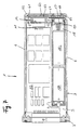
- the device for measured value acquisition is of two parts and comprises a measured value acquisition and storage part 1 and a connection adapter 2.
- Both device parts 1 and 2 each comprise a flat housing.
- Both flat, rectangular housing, the electronics housing 3 and the adapter housing 4 are preferably either made of a heat-resistant plastic or stainless steel.
- the electronics housing 3 comprises a base plate 5, a parallel to this, not shown ceiling plate and two mutually parallel side walls or side plates 6 and two end plates or end walls 7.
- the end walls 7 are made of a stronger material than the other wall parts, and preferably as molded parts which are connected to one another via four connecting rods 8, which are each arranged in pairs in the immediate region of the side walls 6 and run parallel to the longitudinal center axis of the electronics housing 3.
- the connecting rods 8 together with the profiled side walls 7 form a support structure or a Chassis for the electronics housing 3.
- the connecting rods 8 are screwed to the two side walls 7.
- the rods 8 have threaded lugs at one end, with which the rods 8 are screwed into threads 7 a, which are formed in a reinforced profile section 7 b of the side wall 7, which is designed to connect the adapter housing 4.
- the connecting rods 8 have threaded bores or internal threads 8a, into which threaded bolts 7c engage, which are firmly inserted in the other wall 7 in bores provided there.
- the housing 3 can also be welded from two half-shells to form a flat tube, the two end faces 7 being pressed on and welded to the half-shells. Brass rods hold the individual parts together before welding.
- the housing 3 is a plastic housing, only the flat plug-side front (flat socket 9) is pressed on, while the rest of the housing part is made in one piece as a flat pot, making the housing production easy and cheap.
- the side wall 7 for connecting the adapter housing 4 has a central recess into which a flat receptacle 9 is inserted.
- the flat receptacle 9 is formed with a connecting flange or a connecting plate 9a running transversely to the plugging direction, the dimensions of which exceed those of the recess in the side wall 7, and which has holes at its lateral ends which are penetrated by screws 9c which are in threaded holes in the side wall 7 intervene.
- the flat receptacle 9 is attached with its plate 9a from the inside to the wall 7 and soldered onto a circuit board 10 with plug pins, not shown, on which a measurement value detection circuit, not shown is constructed.
- the circuit board 10 extends between the two side walls 7 and is at its end opposite the flat socket part 9 via wire connections 11 in connection with a data socket 12, for example circular cross section, which is inserted into a corresponding recess in the side or rear wall 7.
- the socket 12, which can alternatively also be designed as a plug part, is closed in the exemplary embodiment shown by a cover 13 which has an external thread with which it is screwed into an internal thread of the socket part 12.
- a sealing ring preferably an O-sealing ring 13a, is arranged between the inner annular end face of the cover 13 and a shoulder formed in the socket part 12, in order to ensure a tight seal of the socket part 12 by the cover 13.
- an opening 14 is formed in the rear wall 7 or the rear end wall, specifically in the form of a threaded bore, through which the electronics housing 3 can be filled with filling material, such as glass balls, after all components have been arranged in the electronics housing 3.
- the bore 14 is closed after filling with the contents, as shown in the illustrated embodiment, by a closure element 15, which is designed like a pin and has a threaded bolt in front, with which the closure element can be screwed into the threaded bore 14.
- a chain 16 is connected, which on the other hand is firmly connected to the cover 13 in order to captively connect the two parts 13 and 15 to one another.
- a sealing element for example in the form of an O-ring, is inserted between the threaded section and the head part of the closure part 15 for the sealing closure of the bore 14.
- the rear or rear end wall 7 also has a further circular opening, into which a battery compartment cover 17 can be inserted in a sealing manner.
- the cover 17 is of hollow cylindrical design and has an external thread in the region of its one open end, with which it can be inserted into an internal thread in the circular bore in the end wall 7.
- An O-ring 17a which is inserted into an annular groove of the cylindrical cover 17 and is supported against an annular sealing surface in the wall 7, in turn provides a seal.
- a battery compartment 18 provided in it is accessible, which runs parallel to the longitudinal center axis of the housing 3 and lies next to the circuit board 10.
- the battery compartment is sealed against the interior of the housing 3 and comprises at the inner end a contact part 18a, which is connected to the circuit on the circuit board 10.
- the other, preferably ground contact of the battery compartment 18 is formed in the cover part 17, for example via the Housing 3 is connected in a galvanically conductive manner to the ground connection of the circuit on circuit board 10.
- the electronics housing 3 is hermetically sealed.
- the individual wall parts of the housing 3 are electronically welded together, for example.
- Other sealing measures, such as plugs and socket parts against the housing, are preferably based on O-rings.
- the adapter housing 4 and the electronics housing 3 are preferably designed to be sealed.
- the dense design does not include the flat plug and socket parts 9.24. Rather, these parts are sealed by an O-ring or a similar sealing element if the housing 3 and 4 by the Screws 25 or as shown below, are pressed together by a hook 40.
- the O-ring 22a for sealing the sockets or plugs 9, 24 is arranged in a groove which is formed in the adapter housing wall 22.
- the adapter housing 4 also comprises a base 20 and a ceiling (not shown) opposite this, two mutually opposite parallel side walls 21 and two end wall parts 22, which in turn are in the form of profiles.
- the adapter housing 4 is not designed to be sealed in itself, which is why the side walls 21 can be connected to the end walls 22, for example, by simple screwing measures.
- the end face 22 of the adapter housing 4, which is always exposed or facing away from the electronics housing 3, is provided with a large number, in the exemplary embodiment shown, with five socket parts 23.
- the socket parts 23 are, for example, of cylindrical configuration and each contain a pair of contacts which are led out on the rear side or the side of the sockets 23 located in the housing 4.
- the contact pairs 23a are connected via electrical lines to a flat plug part 24 which is provided on the opposite end wall 22.
- connection sockets 23 in the end wall 22 is effected in that flanges 23b are formed at their outer ends, which have a larger diameter than the socket receiving bores in the end wall 22, and at the inner end section, the socket parts 23 have an external thread provided, on each of a union nut 23c sits.
- the union nut 23c By tightening the union nut 23c, in cooperation with the flange 23b, the bushing parts 23 are braced in the receiving openings of the end wall 22.
- the flat plug part 24 used in the end wall 22 facing the electronics housing 3 is designed as a complementary plug connector element to the flat plug part 9 and is configured essentially like this, namely, inter alia, with a support flange 24a, via which the plug part 24 is connected to the end wall 22 by means of screwing means 24b .
- a screw connection means which comprises two threaded bolts 25 which are rotatably mounted in the adapter housing 4 and whose heads 25a penetrate the outer end wall 22 between two connection sockets 23, while their threaded ends 23c differ from that Protrude electronics housing opposite end wall 22 and are able to engage in threaded bores 26, which are embedded in the flange-shaped thickened part 7b of the end wall 7 of the housing 3.
- the coupling of the adapter housing 4 to the electronics housing 3 takes place in that these two housings are moved towards one another in the direction of their central longitudinal axes, the two flat connector connections 9 and 24 in one another in the last phase of this relative movement engage, which project with their connecting sections in each case over the end walls 9 and 22 over the respective housings, and substantially simultaneously the connecting screws 25 come into engagement with the internal threads 26 formed in the housing 3 by tightening the screws 25 via their head ends 25a one suitable tool, the adapter housing 4 can be mechanically firmly clamped to the electronics housing 3, thereby creating a housing unit.
- An essential aspect of the invention is that a versatile variable measured value recording device is created in that the electronic part 1 is always kept identical, while to the housing 3 of the electronic part 1 configured adapters 2 for the special application are connected, which are characterized by identical housings 4 are, in which adapted to the respective external measuring device connecting parts, such as connection sockets 23 are inserted, which may be connected in the required manner to the flat plug connection connection 24, which, however, does not have to be replaced per se in order to configure the connection with external measuring devices to change.
- the electronic part 1 can be adapted to different measuring tasks in that it is connected via the data connector 12 with the interposition of an interface 70 to a PC (71), by means of which the circuit built on the circuit board 10 is configured by software (see FIG. 8). As can also be seen from FIG.
- the circuit of the electronic part 1 is connected to a plug-in power supply 72 during the configuration process, which replaces the internal battery during this process, in order not to burden it unnecessarily.
- 8 also shows two further adapter parts 2 'and 2' 'which can be connected to the electronics part 1 instead of the adapter 2 and which are configured differently with respect to the connections for the external measuring device.
- FIG. 3 shows a modified device shown, the same parts being provided with the same reference numerals.
- the device shown in FIG. 3 largely corresponds to the device described above, only differently designed elements will be described in more detail.
- the conductive housing cover 17 is connected to the circuit formed on the circuit board 10 via its own line.
- Two intermediate plates 30 and 31 are inserted between the opposing end walls 7 and 22 of the two housings 3 and 4.
- the electronics housing-side plate 30 is firmly connected via countersunk screws 32 to the end wall 7 of the electronics housing 3, which has corresponding threaded bores for this purpose.
- the other or adapter-side plate 31 is firmly connected via screws 33 to the end wall 22 of the adapter housing 4. These screws are also designed as countersunk screws and lie in one axis with the other countersunk screws 32.
- a hermetically sealed connection of the intermediate plate 30 with the end wall 7 is created by an O-ring 34 which sits in an annular groove in the plate 30, projects from it and is in sealing engagement with the wall 7.
- an O-ring 35 is arranged between the plate 31 and the end wall 22 of the adapter housing 4, specifically in an annular groove in the end wall 22. Between the two plates 30 and 31 there is yet another O-ring 36 which is arranged in a Ring groove of the plate 31 lies.
- This O-ring arrangement ensures on the one hand that the electronics housing 3 is hermetically sealed and on the other hand that with a corresponding hermetically sealed design of the adapter housing 4 also the electrical connection in the form of the flat plugs and flat sockets 9 and 24 from the environment is hermetically sealed.
- a special feature of the intermediate plate arrangement of FIG. 3 is that, in contrast to the exemplary embodiment of the device according to the invention dealt with above, the flat connector part 24 is not inserted into the end wall 22 but into the intermediate plate 31, while on the other hand the opposite flat connector device 9 is inserted into a corresponding recess in the another intermediate plate 30 is used.
- This arrangement has the advantage that, on the one hand, the connector connection 24 can be separated from the adapter housing 4 in a simple manner by loosening the screws 33, while on the other hand the connection connection 9 together with the circuit board 10 can be removed from the electronics housing 3 in a similarly simple manner if this is desired.
- the connecting screws 25, which penetrate the adapter plate on the intermediate plate 31, do not engage in threaded holes in the end wall 7 of the electronics housing 3, but in corresponding threaded holes in the electronics plate intermediate plate 30.
- FIGS. 4 to 6 A further modification of the measured value detection device according to the invention is shown in FIGS. 4 to 6.
- the modification essentially relates to the connecting means for connecting the two housings 3 and 4, which is why only these connecting means are described in more detail below.
- the connecting means comprise hook-like tensioning elements 40 arranged on both sides of the adapter housing 4, which engage in recesses on the back of the flange-like laterally projecting extension 7b on the electronics housing 3 and clamp the two housings 3 and 4 together.
- the hooks 40 are pivotally mounted about a pin 41 which is perpendicular to the base plate 20.
- the pin 41 is fixedly connected to a sleeve 42 which is slidably mounted in a channel 43 of the housing 4.
- the sleeve 42 has an internal thread 44 in which the external thread of a piston 45 runs, which is fixedly connected via a piston rod or a bolt 43 to an external cylinder part 47, which has an engagement slot 48 for a screwdriver on its free end face and with which opposite annular end face 49 is present at a housing-fixed stop 50.
- a compression spring 51 is seated on the piston rod 46, which is supported on the one hand on the stop 50 and on the other hand on the piston 45.
- On the pin 41 there is a spring 52 which braces the hook-shaped tensioning element 40 outwards transversely to the longitudinal axis and which passes through the sleeve 42, the piston 45 and the piston rod 46.
- the adapter housing 4 with its flat plug part can be easily plugged onto the flat plug part of the electronics housing arranged opposite one another until the two housings are in contact with one another, whereupon the connecting device is clamped by by inserting a screwdriver into the slot 48 and screwing the piston 45 into the sleeve or the cylinder 42, the hook-shaped clamping member 40 in the direction of the adapter housing 4 is withdrawn and the engagement surface on the flange 7b is pivoted inward behind the flange.
- the hook-like tensioning element with its section 40a articulated on the pin 41 is drawn into the channel 46, the wall of which runs parallel to the longitudinal axis passing through the piston and the piston rod.
- clamping element arrangement is located in the edge region of the other side wall 22 of the adapter housing 4 and is actuated in the same way as the clamping element 40 described above.
- FIG. 7 shows a modified design of the electronics housing 3.
- a protective or closure plate 60 which is pivotably articulated on the end wall 7 of the electronics housing 3 and which connects the data connector 12 and carries the cover 17 for the battery compartment 18.
- the closure plate 60 is designed as a flat cover, which is essentially rectangular and has a bend 61 on one narrow side, with which the plate 60 is pivotable about a shaft 62, which rests in the bottom and top plates of the housing.
- a cushion 63 made of a rubber-elastic, temperature-resistant material which presses on the data connector 12 and seals it when the plate 60 is pivoted into its closed position on the housing 6.
- the closure for the cover or plate 60 is designed as a latch / snap arrangement 64, 65, 66, which has an actuating rotary knob 66 which is rotatably arranged above the battery closure lid 17 and actuates the latch 64, which is rotated by the Button 66 can be withdrawn from the barrier assigned to it, to pivot the lid 60 into its open position.
- the knob 66 is held by the pawl and the cover 60.
- this can also be designed in such a way that, instead of the connector plugs, openings are formed in a housing end wall for external measuring devices, via which the connection terminals are accessible, which are mounted on a drawer which is slidably mounted in the adapter housing and can be pulled out of this to make the terminals accessible without opening this housing.
Landscapes
- Physics & Mathematics (AREA)
- General Physics & Mathematics (AREA)
- Arrangements For Transmission Of Measured Signals (AREA)
Applications Claiming Priority (2)
| Application Number | Priority Date | Filing Date | Title |
|---|---|---|---|
| DE9214646U DE9214646U1 (de) | 1992-10-28 | 1992-10-28 | Vorrichtung zur Meßwerterfassung |
| DE9214646U | 1992-10-28 |
Publications (2)
| Publication Number | Publication Date |
|---|---|
| EP0595022A2 true EP0595022A2 (fr) | 1994-05-04 |
| EP0595022A3 EP0595022A3 (en) | 1995-09-20 |
Family
ID=6885389
Family Applications (1)
| Application Number | Title | Priority Date | Filing Date |
|---|---|---|---|
| EP93115273A Withdrawn EP0595022A3 (en) | 1992-10-28 | 1993-09-22 | Data acquisition device |
Country Status (2)
| Country | Link |
|---|---|
| EP (1) | EP0595022A3 (fr) |
| DE (1) | DE9214646U1 (fr) |
Cited By (2)
| Publication number | Priority date | Publication date | Assignee | Title |
|---|---|---|---|---|
| DE102011009156A1 (de) * | 2011-01-22 | 2012-07-26 | Conti Temic Microelectronic Gmbh | Sensor Baugruppe |
| DE102011080956A1 (de) * | 2011-07-25 | 2013-01-31 | Endress + Hauser Conducta Gesellschaft für Mess- und Regeltechnik mbH + Co. KG | Verfahren und Messstelle zur Messung zumindest einer physikalischen und/oder chemischen Prozessgrößen eines in einem Einwegbehältnis enthaltenen Messmediums |
Families Citing this family (5)
| Publication number | Priority date | Publication date | Assignee | Title |
|---|---|---|---|---|
| DE19510416A1 (de) * | 1995-03-24 | 1996-09-26 | Klein Schanzlin & Becker Ag | Sensormodul |
| DE29606248U1 (de) * | 1996-04-04 | 1997-04-30 | MBS Sulzbach Messwandler GmbH, 74429 Sulzbach-Laufen | Elektrische Baueinheit |
| US7665890B2 (en) * | 2006-06-22 | 2010-02-23 | Watlow Electric Manufacturing Company | Temperature sensor assembly and method of manufacturing thereof |
| DE102016008517A1 (de) * | 2016-07-15 | 2018-01-18 | Testo SE & Co. KGaA | Datenlogger |
| PL131333U1 (pl) * | 2023-03-21 | 2024-09-23 | Uniwersytet Humanistyczno-Przyrodniczy Im. Jana Długosza W Częstochowie | Obudowa zewnętrznej, elektronicznej jednostki sterującej |
Family Cites Families (4)
| Publication number | Priority date | Publication date | Assignee | Title |
|---|---|---|---|---|
| DE8417390U1 (de) * | 1985-03-14 | Böhner, Peter, 8151 Warngau | Gehäuse für ein mehrere Meßfunktionen bzw. Meßbereiche aufweisendes Handmeßgerät | |
| FR2537272B1 (fr) * | 1982-12-03 | 1986-04-04 | Solomat Sa | Appareil de mesure multi-sondes |
| DE3933222A1 (de) * | 1989-10-05 | 1991-04-18 | Ttw Ind & Medizin Messtechnik | Messeinrichtung |
| US5087912A (en) * | 1990-01-31 | 1992-02-11 | Westinghouse Electric Corp. | Universal pressure measurement interface |
-
1992
- 1992-10-28 DE DE9214646U patent/DE9214646U1/de not_active Expired - Lifetime
-
1993
- 1993-09-22 EP EP93115273A patent/EP0595022A3/de not_active Withdrawn
Cited By (3)
| Publication number | Priority date | Publication date | Assignee | Title |
|---|---|---|---|---|
| DE102011009156A1 (de) * | 2011-01-22 | 2012-07-26 | Conti Temic Microelectronic Gmbh | Sensor Baugruppe |
| US9212936B2 (en) | 2011-01-22 | 2015-12-15 | Conti Temic Microelectronic Gmbh | Sensor assembly |
| DE102011080956A1 (de) * | 2011-07-25 | 2013-01-31 | Endress + Hauser Conducta Gesellschaft für Mess- und Regeltechnik mbH + Co. KG | Verfahren und Messstelle zur Messung zumindest einer physikalischen und/oder chemischen Prozessgrößen eines in einem Einwegbehältnis enthaltenen Messmediums |
Also Published As
| Publication number | Publication date |
|---|---|
| EP0595022A3 (en) | 1995-09-20 |
| DE9214646U1 (de) | 1992-12-17 |
Similar Documents
| Publication | Publication Date | Title |
|---|---|---|
| DE112008002986B4 (de) | Verbinder für eine Verwendung mit einem Gerät | |
| DE3635165A1 (de) | Gehaeuseeinrichtung mit druckausgleich | |
| EP3437163A1 (fr) | Dispositif de verrouillage pour connecteur électrique | |
| DE112014005519T5 (de) | Kontaktlagesicherungselement, Kontaktbaugruppe, Verbindergehäusebaugruppe und Verbinder | |
| EP0595022A2 (fr) | Dispositif de saisie de données mesurées | |
| DE202013005113U1 (de) | Batteriesensor | |
| WO2019114863A1 (fr) | Boîtier de raccordement compact | |
| EP3033779B1 (fr) | Dispositif de stockage | |
| DE9114909U1 (de) | Batterie-Anschlußvorrichtung | |
| DE2305584A1 (de) | Kontakttraegerbloecke fuer industrielle steckdosen | |
| DE102006056258A1 (de) | Baugruppe aus elektrischen und/oder elektronischen Bauteilen | |
| DE102012007047B3 (de) | Fahrzeugseitige Dose eines Ladesteckverbinders, insbesondere für Flurförderfahrzeuge | |
| WO2007017023A1 (fr) | Connecteur de charge | |
| DE2915502A1 (de) | Stromentnahmeschiene | |
| EP2027620A2 (fr) | Dispositif de fermeture et/ou de remplissage d'une cellule galvanique individuelle | |
| DE102012209575A1 (de) | Photovoltaik-Paneldose mit verbesserten Aussenanschlüssen | |
| DE102022131236A1 (de) | Elektrisches Endgerät, Herstellungsverfahren und Justierungsverfahren | |
| DE3517301C2 (fr) | ||
| DE69020097T2 (de) | Abgedichteter elektrischer Steckverbinder. | |
| DE2334793B2 (de) | Elektrischer Kabelschuh | |
| EP3527773A1 (fr) | Élément rapporté de fenêtre ainsi que fenêtre, en particulier lucarne | |
| DE3608589A1 (de) | Steckverbindergehaeuse | |
| DE903832C (de) | Anschlussmuffe | |
| DE2531209C3 (de) | Elektrische, einphasige Kompaktsteckvorrichtung für Mittelspannung | |
| DE1590489C3 (de) | Vielpolige Steckvorrichtung |
Legal Events
| Date | Code | Title | Description |
|---|---|---|---|
| PUAI | Public reference made under article 153(3) epc to a published international application that has entered the european phase |
Free format text: ORIGINAL CODE: 0009012 |
|
| AK | Designated contracting states |
Kind code of ref document: A2 Designated state(s): AT BE CH DE DK ES FR GB IT LI LU NL SE |
|
| PUAL | Search report despatched |
Free format text: ORIGINAL CODE: 0009013 |
|
| AK | Designated contracting states |
Kind code of ref document: A3 Designated state(s): AT BE CH DE DK ES FR GB IT LI LU NL SE |
|
| 18D | Application deemed to be withdrawn |
Effective date: 19960402 |