EP0595302B1 - Véhicule guidé automatique à déplacement omnidirectionnel - Google Patents
Véhicule guidé automatique à déplacement omnidirectionnel Download PDFInfo
- Publication number
- EP0595302B1 EP0595302B1 EP93117423A EP93117423A EP0595302B1 EP 0595302 B1 EP0595302 B1 EP 0595302B1 EP 93117423 A EP93117423 A EP 93117423A EP 93117423 A EP93117423 A EP 93117423A EP 0595302 B1 EP0595302 B1 EP 0595302B1
- Authority
- EP
- European Patent Office
- Prior art keywords
- steering
- guided vehicle
- automated guided
- rotor
- drive
- Prior art date
- Legal status (The legal status is an assumption and is not a legal conclusion. Google has not performed a legal analysis and makes no representation as to the accuracy of the status listed.)
- Expired - Lifetime
Links
Images




Classifications
-
- B—PERFORMING OPERATIONS; TRANSPORTING
- B60—VEHICLES IN GENERAL
- B60L—PROPULSION OF ELECTRICALLY-PROPELLED VEHICLES; SUPPLYING ELECTRIC POWER FOR AUXILIARY EQUIPMENT OF ELECTRICALLY-PROPELLED VEHICLES; ELECTRODYNAMIC BRAKE SYSTEMS FOR VEHICLES IN GENERAL; MAGNETIC SUSPENSION OR LEVITATION FOR VEHICLES; MONITORING OPERATING VARIABLES OF ELECTRICALLY-PROPELLED VEHICLES; ELECTRIC SAFETY DEVICES FOR ELECTRICALLY-PROPELLED VEHICLES
- B60L1/00—Supplying electric power to auxiliary equipment of vehicles
- B60L1/003—Supplying electric power to auxiliary equipment of vehicles to auxiliary motors, e.g. for pumps, compressors
-
- B—PERFORMING OPERATIONS; TRANSPORTING
- B60—VEHICLES IN GENERAL
- B60K—ARRANGEMENT OR MOUNTING OF PROPULSION UNITS OR OF TRANSMISSIONS IN VEHICLES; ARRANGEMENT OR MOUNTING OF PLURAL DIVERSE PRIME-MOVERS IN VEHICLES; AUXILIARY DRIVES FOR VEHICLES; INSTRUMENTATION OR DASHBOARDS FOR VEHICLES; ARRANGEMENTS IN CONNECTION WITH COOLING, AIR INTAKE, GAS EXHAUST OR FUEL SUPPLY OF PROPULSION UNITS IN VEHICLES
- B60K7/00—Disposition of motor in, or adjacent to, traction wheel
- B60K7/0007—Disposition of motor in, or adjacent to, traction wheel the motor being electric
-
- B—PERFORMING OPERATIONS; TRANSPORTING
- B60—VEHICLES IN GENERAL
- B60L—PROPULSION OF ELECTRICALLY-PROPELLED VEHICLES; SUPPLYING ELECTRIC POWER FOR AUXILIARY EQUIPMENT OF ELECTRICALLY-PROPELLED VEHICLES; ELECTRODYNAMIC BRAKE SYSTEMS FOR VEHICLES IN GENERAL; MAGNETIC SUSPENSION OR LEVITATION FOR VEHICLES; MONITORING OPERATING VARIABLES OF ELECTRICALLY-PROPELLED VEHICLES; ELECTRIC SAFETY DEVICES FOR ELECTRICALLY-PROPELLED VEHICLES
- B60L50/00—Electric propulsion with power supplied within the vehicle
- B60L50/50—Electric propulsion with power supplied within the vehicle using propulsion power supplied by batteries or fuel cells
-
- B—PERFORMING OPERATIONS; TRANSPORTING
- B62—LAND VEHICLES FOR TRAVELLING OTHERWISE THAN ON RAILS
- B62D—MOTOR VEHICLES; TRAILERS
- B62D1/00—Steering controls, i.e. means for initiating a change of direction of the vehicle
- B62D1/24—Steering controls, i.e. means for initiating a change of direction of the vehicle not vehicle-mounted
- B62D1/28—Steering controls, i.e. means for initiating a change of direction of the vehicle not vehicle-mounted non-mechanical, e.g. following a line or other known markers
-
- B—PERFORMING OPERATIONS; TRANSPORTING
- B62—LAND VEHICLES FOR TRAVELLING OTHERWISE THAN ON RAILS
- B62D—MOTOR VEHICLES; TRAILERS
- B62D7/00—Steering linkage; Stub axles or their mountings
- B62D7/02—Steering linkage; Stub axles or their mountings for pivoted bogies
- B62D7/026—Steering linkage; Stub axles or their mountings for pivoted bogies characterised by comprising more than one bogie, e.g. situated in more than one plane transversal to the longitudinal centre line of the vehicle
-
- H—ELECTRICITY
- H02—GENERATION; CONVERSION OR DISTRIBUTION OF ELECTRIC POWER
- H02J—ELECTRIC POWER NETWORKS; CIRCUIT ARRANGEMENTS OR SYSTEMS FOR SUPPLYING OR DISTRIBUTING ELECTRIC POWER; SYSTEMS FOR STORING ELECTRIC ENERGY
- H02J4/00—Circuit arrangements for mains or distribution networks not specified as AC or DC; Circuit arrangements for mains or distribution networks combining AC and DC sections or sub-networks
- H02J4/20—Networks integrating separated AC and DC power sections
- H02J4/25—Networks integrating separated AC and DC power sections for transfer of electric power between AC and DC networks, e.g. for supplying the DC section within a load from an AC mains system
-
- B—PERFORMING OPERATIONS; TRANSPORTING
- B60—VEHICLES IN GENERAL
- B60K—ARRANGEMENT OR MOUNTING OF PROPULSION UNITS OR OF TRANSMISSIONS IN VEHICLES; ARRANGEMENT OR MOUNTING OF PLURAL DIVERSE PRIME-MOVERS IN VEHICLES; AUXILIARY DRIVES FOR VEHICLES; INSTRUMENTATION OR DASHBOARDS FOR VEHICLES; ARRANGEMENTS IN CONNECTION WITH COOLING, AIR INTAKE, GAS EXHAUST OR FUEL SUPPLY OF PROPULSION UNITS IN VEHICLES
- B60K17/00—Arrangement or mounting of transmissions in vehicles
- B60K17/34—Arrangement or mounting of transmissions in vehicles for driving both front and rear wheels, e.g. four wheel drive vehicles
- B60K17/356—Arrangement or mounting of transmissions in vehicles for driving both front and rear wheels, e.g. four wheel drive vehicles having fluid or electric motor, for driving one or more wheels
-
- B—PERFORMING OPERATIONS; TRANSPORTING
- B60—VEHICLES IN GENERAL
- B60K—ARRANGEMENT OR MOUNTING OF PROPULSION UNITS OR OF TRANSMISSIONS IN VEHICLES; ARRANGEMENT OR MOUNTING OF PLURAL DIVERSE PRIME-MOVERS IN VEHICLES; AUXILIARY DRIVES FOR VEHICLES; INSTRUMENTATION OR DASHBOARDS FOR VEHICLES; ARRANGEMENTS IN CONNECTION WITH COOLING, AIR INTAKE, GAS EXHAUST OR FUEL SUPPLY OF PROPULSION UNITS IN VEHICLES
- B60K17/00—Arrangement or mounting of transmissions in vehicles
- B60K17/34—Arrangement or mounting of transmissions in vehicles for driving both front and rear wheels, e.g. four wheel drive vehicles
- B60K17/358—Arrangement or mounting of transmissions in vehicles for driving both front and rear wheels, e.g. four wheel drive vehicles all driven wheels being steerable
-
- B—PERFORMING OPERATIONS; TRANSPORTING
- B60—VEHICLES IN GENERAL
- B60K—ARRANGEMENT OR MOUNTING OF PROPULSION UNITS OR OF TRANSMISSIONS IN VEHICLES; ARRANGEMENT OR MOUNTING OF PLURAL DIVERSE PRIME-MOVERS IN VEHICLES; AUXILIARY DRIVES FOR VEHICLES; INSTRUMENTATION OR DASHBOARDS FOR VEHICLES; ARRANGEMENTS IN CONNECTION WITH COOLING, AIR INTAKE, GAS EXHAUST OR FUEL SUPPLY OF PROPULSION UNITS IN VEHICLES
- B60K7/00—Disposition of motor in, or adjacent to, traction wheel
- B60K2007/0046—Disposition of motor in, or adjacent to, traction wheel the motor moving together with the vehicle body, i.e. moving independently from the wheel axle
-
- B—PERFORMING OPERATIONS; TRANSPORTING
- B60—VEHICLES IN GENERAL
- B60K—ARRANGEMENT OR MOUNTING OF PROPULSION UNITS OR OF TRANSMISSIONS IN VEHICLES; ARRANGEMENT OR MOUNTING OF PLURAL DIVERSE PRIME-MOVERS IN VEHICLES; AUXILIARY DRIVES FOR VEHICLES; INSTRUMENTATION OR DASHBOARDS FOR VEHICLES; ARRANGEMENTS IN CONNECTION WITH COOLING, AIR INTAKE, GAS EXHAUST OR FUEL SUPPLY OF PROPULSION UNITS IN VEHICLES
- B60K7/00—Disposition of motor in, or adjacent to, traction wheel
- B60K2007/0092—Disposition of motor in, or adjacent to, traction wheel the motor axle being coaxial to the wheel axle
Definitions
- This invention relates to a carrying vehicle which is movable in all directions, comprising: vehicle wheels, and driving wheels with drive mechanisms for driving the vehicle wheels, in which each of the driving wheels are controlled with a steering mechanism so that its moving direction is controlled with the vehicle body maintained unchanged in posture.
- a carrying vehicle movable in all directions (such as an automated guided vehicle on which an article handling robot is mounted), as shown in FIG. 10, has a vehicle body 1; and three driving/steering units 3 arranged on the lower surface of the floor (bottom plate) 2 of the vehicle body 1.
- Each of the driving/steering units 3, as shown in FIG. 11, comprises: a steering mechanism 4 secured to the floor 2; and a drive wheel mechanism 6 coupled to the lower end of the steering shaft 5 of the steering mechanism 4.
- a driving wheel (or driving tire) 9 is fitted on the outer rotor 8 of a drive motor 7 of outer rotor type.
- a battery On the vehicle body 1 are installed a battery, a power source unit such as a power converter for controlling the supply of power from the battery to the steering motor of the steering mechanism 4 and to the above-described drive motor, and a driving/steering control device for receiving feedback signals from the steering motor and the drive motor to control, for instance, the power converter.
- a power source unit such as a power converter for controlling the supply of power from the battery to the steering motor of the steering mechanism 4 and to the above-described drive motor
- a driving/steering control device for receiving feedback signals from the steering motor and the drive motor to control, for instance, the power converter.
- FIG. 12 shows one example of a passageway along which the automated guided vehicle A moves.
- reference characters STA, STB and STC designate article handling stations in the yard.
- the automated guided vehicle A When it is required for the automated guided vehicle A to approach any one of the article handling stations and stop there, its movement is limited by other devices (not shown) to some extent; that is, the automated guided vehicle A is forced to approach the station from a drive route while moving sideward which is spaced a certain distance from the line of the stations.
- the automated guided vehicle A moves to the stations STA, STB and STC in the stated order; that is, it moves to positions 1, 2, 3, 4 and 5 in the stated order.
- the conventional automated guided vehicle is provided with a stopper or other suitable control means to prevent the angle of relative rotation of the vehicle from becoming more than 360°.
- a rest swing operation (in other words, a rest steering operation) is carried out; that is, only the steering shaft is turned 180°.
- the rest swing operation raises the following problems: First of all, the rest swing operation takes a relatively long time. Furthermore, in the rest swing operation, the grounding surface of the driving tire is rubbed against the surface of the yard, so that the driving tire is worn; that is, it is lowered in durability. In addition, when the automated guided vehicle is used in the clean room, the particle produced by the rubbing of the tire cannot be disregarded.
- DE-U-77 01 751 discloses a vehicle comprising wheel drive means including a drive mechanism on one vehicle wheel, a steering means for said one wheel for controlling a direction of said wheel to control a direction of movement of the vehicle, and power transmitting and receiving means for transmitting an electric power between an electric power source unit providing on the body of a vehicle through a stationary electrode member provided on a member which is stationary with respect to the body of the vehicle and a rotary electrode member provided on a member which is rotatable with respect to the stationary electrode member, the stationary electrode member and the rotary electrode member being included into the power transmitting and receiving means.
- an object of this invention is to eliminate the above-described difficulties accompanying a conventional automated guided vehicle movable in all directions. More specifically, an object of the invention is to provide an automated guided vehicle movable in all directions in which the cables will never be broken due to twisted, and it is unnecessary to perform the above-described rest swing operation.
- the cable connected to the drive wheel mechanism is extended through the inside of the steering shaft and connected to the rotary electrode member which is rotated together with the steering shaft, and the cable connected to the steering mechanism is also extended through the inside of the steering shaft and connected to the rotary electrode member.
- the rotary electrode member is rotatable with respect to the stationary electrode member which is provided on the member which is on the stationary side of the vehicle body.
- FIG. 1 An automated guided vehicle movable in all directions, which constitutes a first embodiment of this invention, will be described with reference mainly to FIG. 1.
- reference numeral 10 designates a steering mechanism; 11, the casing of the steering mechanism. 10; 30, a drive wheel mechanism; 31, a bracket of the drive wheel mechanism 30; 50, a slip ring device; and 51, the casing of the slip ring device 50.
- the casing 11 of the steering mechanism 10 is in the form of a cylinder with the ends closed with upper and lower end lids 11U and 11D.
- the casing 11 is secured to the floor 2 of the vehicle body with the upper end cover 11U fastened to the lower surface of the floor 2 with bolts or the like.
- the casing 11 supports a hollow steering shaft 12 with the aid of bearings 13 and 14 in such a manner that the shaft 12 is held vertical.
- the bracket 31 of the drive wheel mechanism 30 has right and left side walls 31R which are coupled through a bracket coupling plate to each other.
- the lower end portion of the steering shaft 12, which is extended downwardly through the lower end lid 11D, is fitted in a recess 32 which is formed in the bracket coupling board of the bracket 31 of the drive wheel mechanism 30.
- the lower end portion of the steering shaft 12, is coupled to the coupling board with bolts or the like; that is, the coupling board is supported by the lower end portion of the steering shaft 12 which is extended through the lower end lid 11D.
- the upper end portion thus protruded is joined to the lower end portion of the hollow slip ring shaft 52 of the slip ring device 50.
- a protective ring 80 is fitted in the hole 2A of the floor 2, and secured to the upper end lid 11U of the casing 11 of the steering mechanism 10, in such a manner that it surrounds the joint of the steering shaft 12 and the slip ring shaft 52.
- the casing 51 of the slip ring device 50 supports the slip ring shaft 52 through bearings 53 and 54 and is secured on the protective ring 80.
- the rotor 15 of a steering motor M1, the magnetic pole rotor 16 of a rotation sensor S1 such as an encoder, and the movable friction board 17 of a steering electromagnetic brake B1 are mounted on the steering shaft 12 of the steering mechanism 10.
- the stator 18 of the steering motor M1, the pickup element (pickup coil) 19 of the rotation sensor 20, and the stationary friction board and exciting section 20 of the steering electromagnetic brake B1 are secured to the casing 11.
- reference numeral 21 designates a power cable connected to the steering motor M1; 22, a signal line connected to the rotation sensor S1; and 23, a power cable connected to the steering electromagnetic brake B1 (the cables and the line are assembled into one unit 61D).
- the power cable 21, the signal line 22, and the power cable 23 are extended outside through wire holes 11a, 11b and 11c formed in the side wall of the casing 11, respectively, and are then bundled outside the casing 11, and extended into the vehicle body through a wire hole 2B formed in the floor (bottom board) 2 of the automated guided vehicle.
- the power cable 21 of the steering motor M1, and the power cable 22 of the steering electromagnetic brake B1 are connected to a motor power source unit and a brake power source unit, respectively, and the signal line of the rotation sensor S1 is connected to a control unit.
- the drive wheel mechanism 30 incorporates a drive motor M2.
- the drive motor M2 is of outer rotor type, and its motor shaft (being an axle) is supported by the brackets 31R and 31L at both ends.
- the outer rotor 35 is supported through bearings 33A and 33B on the motor shaft 33.
- a driving tire 9 is fixedly put on the outer rotor 35.
- the motor shaft 33 is in the form of a hollow tube.
- the stator 37 of the motor M2, the pickup element 38 of a rotation sensor S2 such as an encoder, and the stationary friction board and exciting section 39 of a drive wheel electromagnetic brake B2 are mounted on the hollow motor shift 33.
- reference numeral 43 designates a power cable connected to the drive motor M2; 44, a signal line connected to the rotation sensor S2; and 45, a power cable connected to the drive wheel electromagnetic brake B2 (the assembly of those lines 43, 44 and 45 being designated by 61C).
- the power cable 43, the signal line 44, and the power cable 45 are extended into the hollow motor shaft 33 respectively through wire boles 33a, 33b and 34c formed in the cylindrical wall of the motor shaft 33, and are then extended outside through the left end of the motor shaft 33 and a hole 31a formed in the left side wall 31L of the casing 31.
- Those lines 43, 44 and 45 thus extended are further extended through a hole 31b formed in the left side wall 31L and then through a hole 31A, which is communicated with the recess 32, into the steering shaft 12 and the slip ring shaft 52.
- a disk-type slip ring 55 (FIG. 3) and ring-type slip rings 56 (or 56a through 56e) (FIG. 2), which form a rotary electrode section, are mounted on the slip ring shaft 52.
- Terminal sections 59 and 60 (which form a stationary electrode section) are provided on the inner surface of the housing 51.
- the terminal section 59 has electrically conducive brushes 57 (or 57a, 57b and 57c) which are elastically brought in slide contact with conductors 55a, 55b and 55c of the disk-type slip ring 55, respectively.
- the terminal section 60 has electrically conductive brushes 58 (or 58a through 58e), which are elastically brought into slide contact with the ring-type slip rings 56 (56a through 56e), respectively.
- the stationary electrode section, the brushes, and the rotary electrode section form signal/power transmitting and receiving means.
- the power cable 43 of the drive motor M2, and the power cable 45 of the drive wheel electromagnetic brake B2 are extended outside the slip ring shaft 52 through wire holes 52a through 52e formed in the cylindrical wall of the slip ring shaft 52, and then connected to the respective ring-type slip rings 56a through 56e.
- the signal line 44 of the rotation sensor S2 is extended outside the slip ring shaft 52 through a wire hole 52f formed in the cylindrical wall of the slip ring shaft 52, and then connected to the disk-type slip ring 55.
- a power cable connected to the motor power source unit, and a power cable connected to the brake power source unit are extended into the casing 51 through a wire hole 51a formed in the casing 51, and then extended through a wire hole 60a formed in the terminal section 60 and connected to the respective terminal in the terminal section 60.
- a signal line 61B connected to the aforementioned control unit is extended into the casing 51 through the wire hole 51a, and connected to the respective terminal 59.
- the drive wheel mechanism 30, the steering shaft 12, and the rotary electrode section turns as one unit, and the cable 61C of the drive wheel mechanism 30 is extended through the inside of the steering shaft 12 and connected to the rotary electrode section. Hence, those cables will never be twisted.
- FIG. 4 shows a second embodiment of the invention.
- the second embodiment is different from the first embodiment only in the following points:
- the steering shaft 12 and the slip ring shaft 52 of the first embodiment are formed into one unit. That is, the steering shaft 12 has a prolongation 12A, which is protruded into the casing 51, so that the prolongation 12A is employed as the slip ring 52.
- the second embodiment dispenses with the bearings 53 and 54 of the protective ring 80 of the first embodiment shown in FIG. 1.
- FIG. 5 shows a third embodiment of the invention.
- the steering motor M1 is of outer rotor type, and its rotor 111 is employed as the steering shaft. That is, the rotor 111 has a prolongation 111A which serves as the above-described casing 51.
- the upper open end of the rotor 111 is put on the outer cylindrical surface of an annular protrusion 112 through a bearing 75 which is extended from a mounting member 111U (which is one of the end lids of the motor M1) which is secured to the lower surface of the floor 2; whereas the lower open end of the rotor 111 is put on the outer cylindrical surface of another mounting member 111D (which is the other end lid of the motor M1) through a bearing 76.
- the shaft (or hollow stationary shaft) 120 of the steering motor M1 is integral with the slip ring shaft 52. That is, those shafts 120 and 52 provided as one unit are supported by the end lids 111U and 111D.
- a steering electromagnetic brake B1 is set inside a bracket 82 which is secured to the lower end of the rotor 111.
- a bracket 31 is coupled through the bracket 82 and a coupling board 83 to the rotor 111.
- the bracket 82 has a protrusion 82A extended downwardly, which is engaged with a recess 83A formed in the coupling board 83.
- the coupling board 83 has a wire hole 83a.
- the stationary friction board and exciting section 20 of the steering electromagnetic brake B1 is provided on the end lid 111D, and the movable friction board 17 is secured to the bracket 82.
- the power cable 43 of a drive motor M2, the signal line of a rotation sensor S2, and the power cable 45 of a drive wheel electromagnetic brake B2 are extended through a wire hole 43 formed in the side wall of the bracket 31 and through a wire hole 83a formed in the coupling board 83.
- the power cable 43 of the drive motor M2, and the power cable 45 of the drive wheel electromagnetic brake B2 are extended through a wire hole 111a formed in the cylindrical wall of the rotor 111 into the rotor 111, and connected to the respective terminals in the terminal section 60; while the signal line 44 of the rotation sensor S2 is extended through a wire hole 111b formed in the cylindrical wall of the rotor 111, and connected to the respective terminal in the terminal section 59.
- the power cables from the power source units, and the signal line from the control unit are connected to the ring section and the disk section.
- the power cable 23 of the steering electromagnetic brake B1 is extended through a wire hole 120b in the shaft 120 and through the inside of the slip ring shaft 52.
- the signal line 22 of the rotation sensor S1 is extended through a wire passageway 111c formed in the end lid 111D, and through the inside of the shaft 120 into the inside of the slip ring shaft 52.
- FIG. 6 shows a fourth embodiment of the invention.
- its steering motor M1 is of outer rotor type.
- the fourth embodiment is different from the third embodiment in that a slip ring shaft 52 and terminal sections 59 and 60 are provided in the hollow shaft 130 of the steering motor M1 in such a manner that they are coaxial with the hollow shaft 130, and the slip ring shaft 52 is put on a shaft member 140 which is extended vertically from the lower end lid 11D of the rotor 111.
- the upper end of the hollow shaft 130 is closed with an end lid 131U, and has a flange 130A which is secured to the rear surface of the floor 2 with bolts or the like.
- the shaft member 140 has a hole 140A which is opened downwardly.
- the movable friction board 1 of a steering electromagnetic brake B1 is mounted on the upper end portion of the shaft member 140, and the stationary friction board and exciting section 20 of the brake B1 is fixedly secured to the aforementioned end lid 131U.
- reference characters 131a and 131b designate wire holes formed in the end lid 131U.
- the lower end lid 111D of the rotor 111 has a protrusion 111A which is fitted in a recess 83A formed in a coupling board 83, and a wire hole 111a.
- FIG. 7 shows a fifth embodiment of the invention.
- its steering motor M1 is of outer rotor type.
- the fifth embodiment is substantially different from the third and fourth embodiments in that a hollow slip ring shaft 52 is provided outside the rotor 150 of the motor in such a manner that the shaft 52 is coaxial with the steering motor M1, and a stationary frame 160 surrounds the slip ring shaft 52 with a space G therebetween.
- the stationary frame 160 has an internal annular member 160A with an upper flange 160B.
- the upper flange 160B is secured to the floor 2 with bolts or the like.
- Wire holes 160a and 160b are formed in the side wall of the stationary frame 160.
- the inside of the rotor 150 is divided by a partition wall 151 into a motor chamber A and a brake chamber B.
- the upper end portion of the rotor 150 is fitted in the internal annular member 160A of the stationary frame 160 through a bearing 75, and the lower end portion is fitted in the lower end portion of the stationary frame 160 through a bearing 76.
- the lower end of the rotor 150 is closed with an end lid 151D.
- the end lid 151D has a protrusion 152D, which is engaged with a recess 83A formed in a coupling board 83.
- the shaft 170 of the steering motor M1 is hollow, and has a flange 170A at the upper end which closes the upper end of the rotor 150.
- the lower end portion of the shaft 170 is supported through a bearing 54 by the aforementioned partition wall 151.
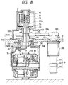
- FIG. 8 shows a sixth embodiment of the invention.
- a steering mechanism 10 is provided in parallel with a drive wheel mechanism 30, and secured through a speed reducing unit 200 to the lower surface of the floor 2.
- the speed reducing unit 200 has a drive shaft 201 protruded above the floor 2, on which a toothed pulley 202 is fixedly mounted.
- the drive wheel mechanism 30 is mounted on the floor 2 through a mounting member 190, a bearing 191, and a mounting member 192.
- a steering shaft 120 having a prolongation 120A is mounted vertical on the mounting member 190.
- the mounting member 190 is in the form of a short tube.
- the lower end portion of the mounting member 190 is fitted in a recess 83A formed in a coupling board 83, and secured to the coupling board 83 with bolts or the like.
- the mounting member 192 comprises an upper member 192A which is in the form of a short tube with a flange; and a lower member 192B which is also in the form of a short tube.
- the mounting member 192 is engaged a hole 2A formed in the floor 2.
- the mounting member 190 is fitted in the mounting member 192 through the bearing 191.
- the prolongation 120A of the steering shaft 120 is extended into the casing 51 of a slip ring device; that is, it serves as a slip ring shaft.
- a toothed pulley 203 is fixedly mounted on the end portion of the slip ring shaft which end portion is located outside the casing 51.
- a toothed belt is laid over the toothed pulley 203 and the above-described toothed pulley 202.
- reference numeral 300 designates a slip ring supporting frame.
- transmission and reception of electric power and signals for the vehicle body, the steering mechanism, and the drive mechanism are carried out through the slip ring device 50.
- they may be performed by using different means as shown in FIG. 9.
- FIG. 9 shows a seventh embodiment of the invention.
- reference character DR designates a driver (or power source unit).
- the driver DR provides controlled driving electric power, which is applied through a slip ring device SLip forming a signal/power transmitting and receiving device B (encircled by the broken line in FIG. 9) to the motors in the motor drive mechanism and the steering mechanism.
- the output of the sensor such as the above-described rotation sensor S1 is modulated by a converter device A, and applied through a rotary transformer RTr forming the signal/power transmitting and receiving device B to a converter device C, where it is demodulated.
- the output of the converter device C is applied to the driver DR.
- transmission and reception of the signals are carried out through the rotary transformer, and transmission and reception of the driving electric power are performed through the slip ring device; however, the invention is not limited thereto or thereby. That is, a mercury switch may be employed for transmission and reception of the driving electric power.
- the cable connected to the drive wheel mechanism is extended through the inside of the steering shaft and connected to the rotary electrode section which is rotated together with the steering shaft, and the cable connected to the steering mechanism is also extended through the inside of the steering shaft and connected to the rotary electrode section.
- the rotary electrode section is rotatable with respect to the stationary electrode section which is provided on the member which is on the stationary side of the vehicle body.
- the automated guided vehicle of the invention unlike the conventional one, it is unnecessary to use the stoppers, and it is unnecessary to perform the rest swing operation. That is, the automated guided vehicle according to the invention is free from the difficulty that particle is produced during the rest swing operation. Therefore, the automated guided vehicle can be effectively used in a clean room.
Landscapes
- Engineering & Computer Science (AREA)
- Transportation (AREA)
- Mechanical Engineering (AREA)
- Chemical & Material Sciences (AREA)
- Combustion & Propulsion (AREA)
- Power Engineering (AREA)
- Life Sciences & Earth Sciences (AREA)
- Sustainable Development (AREA)
- Sustainable Energy (AREA)
- Power Steering Mechanism (AREA)
- Arrangement Or Mounting Of Propulsion Units For Vehicles (AREA)
- Arrangement And Driving Of Transmission Devices (AREA)
- Arrangements For Transmission Of Measured Signals (AREA)
- Control Of Position, Course, Altitude, Or Attitude Of Moving Bodies (AREA)
Claims (8)
- Véhicule guidé automatique ayant une pluralité de roues (9) déplaçables dans toutes les directions, comprenant:des moyens d'entraînement de roues (M2, 30) comprenant un mécanisme d'entraînement (30) sur chacune de ladite pluralité de roues (9), permettant aux roues de véhicule (9) respectives de déplacer ledit véhicule automatique;un moyen de guidage directionnel (M1, 10) destiné à chaque roue (9), afin de contrôler une direction de la roue (9) respective, en vue de contrôler une direction de déplacement ou véhicule guidé automatique sans modifier le cap du véhicule guidé automatique; etdes moyens de transmission et de réception de signaux/puissance (50, 55 à 60) servant à transmettre une puissance électrique entre une unité formant source de puissance électrique prévue sur un corps (1) du véhicule guidé automatique et les mécanismes d'entraînement (30) et les moyens de direction (M1, 10) respectifs pour transmettre des signaux ce commande entre une unité de commande prévue sur un corps (1) du véhicule guidé automatique et les mécanismes d'entraînement (30) et les moyens de commande (M1, 10), via un organe formant électrode (57, 58) stationnaire, prévu sur un organe (51; 160) qui est stationnaire par rapport au corps (1) du véhicule guidé automatique, et un organe formant électrode (55, 56) rotatif prévu sur un organe (52; 111) qui est tournant par rapport à l'organe formant électrode stationnaire (57, 58), l'organe formant électrode stationnaire (57, 58) et l'organe formant électrode rotative étant inclus dans les moyens de transmission et de réception de signaux/puissance (50, 55 à 60),dans lequel chaque dit moyen de direction (M1, 10) comprend un moyen servant à faire tourner ladite roue d entraînement (9) respective et le mécanisme d'entraînement (30) dans une direction autour d'un axe, suivant un angle de 360° et ledit moyen servant a faire tourner ladite roue d'entraînement respective et le mécanisme d'entraînement comprend un moteur de guidage directionnel (M1),
dans lequel le moyen de direction (M1, 10) comprend en outre:un arbre de direction (12) et un rotor (15) sur l'arbre de direction (12), le rotor (15) étant couplé à un mécanisme d'entraînement (9) respectif, le rotor (15) étant disposé à l'extérieur de l'arbre de direction (12) et pouvant se déplacer an réponse à l'activation d'un stator (18), en réponse auxdits signaux de commande, afin de faire tourner les mécanismes d'entraînement (30) et la roue d'entraînement (9) autour d'un axe de l'arbre de direction (12), etdans lequel l'organe formant électrode rotative est une bague de contact (55, 56) prévue sur l'arbre de direction (12) et l'organe formant stationnaire est un balai (57, 58) monté en contact de glissement élastique avec la bague de contact (55, 56). - Véhicule guidé automatique selon la revendication 1, dans lequel les moyens de direction (M1, 10) comprennent:un moteur (M1) disposé entre l'arbre de direction (12) et le rotor (15), le moteur (M1) ayant un arbre rotatif sur lequel la bague glissante est montée coaxialement,dans lequel l'arbre rotatif du moteur comprend ledit arbre de direction (12), et
dans lequel l'arbre de direction (12) est creux et des câbles (61, 61A à 61D) de l'unité formant source de puissance électrique et l'unité de commande traversent l'arbre de direction (12) creux. - Véhicule guidé automatique selon la revendication 1, dans lequel la bague glissante (52) est montée sur une périphérie extérieure du rotor (150) et le balai (58) est monté sur un cadre disposé à l'extérieur du rotor (150).
- Véhicule guidé automatique selon la revendication 1, dans lequel le moyen de direction (M1, 10) est disposé parallèlement au moyen d'entraînement de roues (M2, 30) afin d'entraîner les moyens d'entraînement de roues (M2, 30) via un dispositif de transmission (200).
- Véhicule guidé automatique selon la revendication 1, dans lequel les moyens de transmission et de réception de signaux/puissance comprennent un transformateur rotatif (RTr) qui effectue une transmission des signaux de commande, et dans lequel le balai (57, 58) effectue une transmission de la puissance électrique.
- Véhicule guidé automatique ayant une pluralité de roues (9) déplaçables dans toutes les directions, comprenant:des moyens d'entraînement de roues (M2, 30) comprenant un mécanisme d'entraînement (30) sur chacune de ladite pluralité de roues (9), permettant aux roues de véhicule (9) respectives de déplacer ledit véhicule automatique;un moyen de guidage directionnel (M1, 10) destiné à chaque roue (9), afin de contrôler une direction de la roue (9) respective, an vue de contrôler une direction de déplacement du véhicule guidé automatique sans modifier le cap du véhicule guidé automatique; etdes moyens de transmission et de réception de signaux/puissance (50, 55 à 60) servant à transmettre une puissance électrique entre une unité formant source de puissance électrique prévue sur un corps (1) du véhicule guidé automatique et les mécanismes d'entraînement (30) respectifs et les moyens de direction (M1, 10), et afin de transmettre des signaux de commande entre une unité de commande prévue sur le corps du véhicule guidé automatique et les mécanismes d'entraînement (30) respectifs et les moyens de direction (M1, 10) via un organe formant électrode stationnaire (55, 56), prévu sur un organe (52; 160) qui est stationnaire par rapport au corps (1) du véhicule guidé automatique, et un organe formant électrode rotative (57, 58) prévu sur un organe qui est rotatif par rapport à l'organe formant électrode stationnaire (55, 56), et l'organe formant électrode rotative étant inclus dans les moyens de transmission et de réception de signaux/puissance (50, 55 à 60),dans lequel chaque dit moyen de direction (M1, 10) comprend un moyen servant à faire tourner une dite roue d'entraînement (9) respective et un mécanisme d'entraînement (30) dans une direction autour d'un axe, suivant un angle de 360°,
dans lequel ledit moyen (M1, 10) servant à faire tourner ladite roue d'entraînement respective et le mécanisme d'entraînement comprend un moteur de direction (M1),
dans lequel le moyen de direction (M1, 10) comprend en outre:un arbre de direction (12) et un rotor (111, 150) sur l'arbre de direction, le rotor (111, 150) étant couplé à un mécanisme d'entraînement (30) respectif, le rotor (111) étant disposé à l'extérieur de l'arbre de direction (12) et pouvant se déplacer en réponse à l'activation d'un stator (18), en réponse auxdits signaux de commande, afin de faire tourner le mécanismes d'entraînement (30) et la roue d'entraînement autour d'un axe de l'arbre de direction (12), etdans lequel l'organe formant électrode rotative est une bague de contact (55, 56) prévue sur l'arbre de direction (12) et l'organe formant électrode rotative comprend des balais (57, 58) montés en contact de glissement élastique avec la bague glissante (55, 56). - Véhicule guidé automatique selon la revendication 6, dans lequel un moteur (M1) est disposé entre l'arbre de direction et le rotor, le moteur (M1) ayant un arbre rotatif sur lequel la bague glissante (52) est montée coaxialement,
dans lequel le rotor (111, 150) comprend l'arbre rotatif du moteur (M1), et
dans lequel le rotor (111) comprend un trou (111a, 111b) destiné à loger des câbles (61, 61A à 61D) de l'unité formant source de puissance électrique et de l'unité de commande. - Véhicule guidé automatique selon la revendication 5, dans lequel les moyens de transmission et de réception de signaux/puissance comprennent un transformateur rotatif (RTr) qui effectue une transmission des signaux de commande, et dans lequel le balai (57, 58) effectue une transmission de la puissance électrique.
Applications Claiming Priority (2)
| Application Number | Priority Date | Filing Date | Title |
|---|---|---|---|
| JP290145/92 | 1992-10-28 | ||
| JP29014592A JP3437199B2 (ja) | 1992-10-28 | 1992-10-28 | クリーンルーム用無人搬送車 |
Publications (2)
| Publication Number | Publication Date |
|---|---|
| EP0595302A1 EP0595302A1 (fr) | 1994-05-04 |
| EP0595302B1 true EP0595302B1 (fr) | 1997-03-05 |
Family
ID=17752365
Family Applications (1)
| Application Number | Title | Priority Date | Filing Date |
|---|---|---|---|
| EP93117423A Expired - Lifetime EP0595302B1 (fr) | 1992-10-28 | 1993-10-27 | Véhicule guidé automatique à déplacement omnidirectionnel |
Country Status (7)
| Country | Link |
|---|---|
| US (1) | US5450320A (fr) |
| EP (1) | EP0595302B1 (fr) |
| JP (1) | JP3437199B2 (fr) |
| KR (1) | KR100336405B1 (fr) |
| DE (1) | DE69308467T2 (fr) |
| MY (1) | MY114762A (fr) |
| TW (1) | TW308137U (fr) |
Families Citing this family (32)
| Publication number | Priority date | Publication date | Assignee | Title |
|---|---|---|---|---|
| JP3549421B2 (ja) * | 1998-12-24 | 2004-08-04 | Tcm株式会社 | 旋回式車輪装置を有する産業車両 |
| JP3633413B2 (ja) * | 2000-01-06 | 2005-03-30 | ナイルス株式会社 | 回転コネクタ装置 |
| US8192137B2 (en) | 2004-05-03 | 2012-06-05 | Jervis B. Webb Company | Automatic transport loading system and method |
| US7980808B2 (en) * | 2004-05-03 | 2011-07-19 | Jervis B. Webb Company | Automatic transport loading system and method |
| US8075243B2 (en) | 2004-05-03 | 2011-12-13 | Jervis B. Webb Company | Automatic transport loading system and method |
| BRPI0511407A (pt) * | 2004-05-03 | 2008-01-22 | Webb Int Co Jerwis B | sistema para carga automática de transporte utilizando o método de referência cruzada |
| US8210791B2 (en) * | 2004-05-03 | 2012-07-03 | Jervis B. Webb Company | Automatic transport loading system and method |
| WO2006060854A1 (fr) * | 2004-12-07 | 2006-06-15 | Ronald Lewis Lambert | Vehicule de transport terrestre robotise |
| US20060276958A1 (en) * | 2005-06-02 | 2006-12-07 | Jervis B. Webb Company | Inertial navigational guidance system for a driverless vehicle utilizing laser obstacle sensors |
| DE102005058942A1 (de) * | 2005-12-09 | 2007-07-12 | Zf Friedrichshafen Ag | Antrieb für Flurförderfahrzeuge |
| US7617890B2 (en) * | 2006-05-08 | 2009-11-17 | Deere & Company | Steering mechanism for self-propelled mower |
| US7418328B2 (en) * | 2006-05-08 | 2008-08-26 | Deere & Company | Steering logic for self-propelled mower |
| JP2008001273A (ja) * | 2006-06-23 | 2008-01-10 | National Agriculture & Food Research Organization | 走行台車の操向装置 |
| DE102007035010A1 (de) | 2007-07-26 | 2009-01-29 | Jungheinrich Ag | Lenkeinheit für ein Rad eines Flurförderzeugs |
| US20090128139A1 (en) * | 2007-11-20 | 2009-05-21 | Drenth Joseph B | Magnet position locator |
| JP5305810B2 (ja) * | 2008-09-26 | 2013-10-02 | 愛知機械テクノシステム株式会社 | 無人搬送車 |
| US20110141771A1 (en) * | 2010-12-07 | 2011-06-16 | Karl Kyrberg | Electric power system including power converter and rotary transformer and method of assembling same |
| US10144436B2 (en) | 2016-04-29 | 2018-12-04 | Sujay A. Phadke | Ropeway vehicle transportation network |
| US10059349B2 (en) | 2016-04-29 | 2018-08-28 | Sujay A. Phadke | Ropeway vehicles |
| GB2582640B (en) * | 2019-03-29 | 2021-10-27 | Protean Electric Ltd | A drive arrangement for a vehicle |
| WO2020259833A1 (fr) * | 2019-06-26 | 2020-12-30 | Abb Schweiz Ag | Unité d'entraînement pour un véhicule guidé automatisé et véhicule guidé automatisé comprenant une pluralité d'unités d'entraînement |
| US11635351B2 (en) * | 2019-06-26 | 2023-04-25 | Abb Schweiz Ag | Methods of calibrating positions of wheels in an automated guided vehicle, and automated guided vehicle |
| CN113993769B (zh) * | 2019-06-26 | 2023-11-21 | Abb瑞士股份有限公司 | 制动自主引导车辆的方法和自主引导车辆 |
| JP7487591B2 (ja) | 2020-07-13 | 2024-05-21 | 住友電装株式会社 | 配線部材の配索構造 |
| JP7380460B2 (ja) * | 2020-07-13 | 2023-11-15 | 住友電装株式会社 | 足回り用配線モジュール及び足回り用配線モジュールの配索構造 |
| JP7456315B2 (ja) * | 2020-07-13 | 2024-03-27 | 住友電装株式会社 | 車輪側機器及び足回り用配線装置 |
| JP7380461B2 (ja) * | 2020-07-13 | 2023-11-15 | 住友電装株式会社 | 足回り用配線モジュール及び足回り用配線モジュールの配索構造 |
| JP7834426B2 (ja) * | 2020-07-13 | 2026-03-24 | 住友電装株式会社 | 足回り用配線モジュール及び足回り用配線モジュールの配索構造 |
| KR20220159807A (ko) * | 2021-05-26 | 2022-12-05 | 현대자동차주식회사 | 360도 회전이 가능한 휠 장치 및 이를 이용한 다륜 구동 모빌리티 |
| KR20230098457A (ko) * | 2021-12-24 | 2023-07-04 | 현대자동차주식회사 | 주행용 모듈 및 그 주행용 모듈을 포함하는 모빌리티 |
| KR102747839B1 (ko) * | 2022-03-10 | 2024-12-31 | 에이치엘만도 주식회사 | 자율주행충전로봇 제어 방법, 자율주행충전로봇 제어 장치, 제어 방법을 수행하기 위한 컴퓨터 프로그램 및 컴퓨터 판독 가능한 기록 매체 |
| AT528059A1 (de) * | 2024-03-13 | 2025-09-15 | MTA GmbH | Vollintegrierte, kompakte und endlos drehende Antriebseinheit für sicheres Fahren von fahrerlosen omnidirektionalen Transportfahrzeugen |
Family Cites Families (12)
| Publication number | Priority date | Publication date | Assignee | Title |
|---|---|---|---|---|
| GB1089755A (en) * | 1965-02-03 | 1967-11-08 | Lansing Bagnall Ltd | Improvements in or relating to motor driven trucks |
| FR1522417A (fr) * | 1967-03-14 | 1968-04-26 | Comp Generale Electricite | Véhicules de construction modulaire |
| DE7701751U1 (de) * | 1977-01-21 | 1978-06-08 | Siemens Ag, 1000 Berlin Und 8000 Muenchen | Dreiraedriges kleinlastfahrzeug |
| JPS58142509A (ja) * | 1982-02-19 | 1983-08-24 | Hitachi Ltd | 回転部分を有する自動車部品への電源供給装置 |
| US4547636A (en) * | 1982-07-28 | 1985-10-15 | Kabushiki Kaisha Tokai-Rika-Denki-Seisakusho | Slidable contact assembly |
| US4530056A (en) * | 1982-10-28 | 1985-07-16 | Modular Automation Corp. | Automated guided vehicle system |
| CH667929A5 (de) * | 1984-08-10 | 1988-11-15 | Jd Technologie Ag | Antriebs- und lenksteuereinrichtung fuer fahrerlose transporteinheiten. |
| US4633966A (en) * | 1985-09-12 | 1987-01-06 | Caterpillar Industrial Inc. | Sensor mounting arrangement |
| US5127485A (en) * | 1988-06-29 | 1992-07-07 | Aisin Aw Co., Ltd. | Electric motorized wheel with integral motorized cooling oil pump |
| US5170352A (en) * | 1990-05-07 | 1992-12-08 | Fmc Corporation | Multi-purpose autonomous vehicle with path plotting |
| US5281901A (en) * | 1990-12-03 | 1994-01-25 | Eaton-Kenway, Inc. | Downward compatible AGV system and methods |
| US5128598A (en) * | 1990-12-13 | 1992-07-07 | Raymond Corporation | Material handling vehicle steering system |
-
1992
- 1992-10-28 JP JP29014592A patent/JP3437199B2/ja not_active Expired - Fee Related
-
1993
- 1993-10-04 TW TW085212833U patent/TW308137U/zh unknown
- 1993-10-14 KR KR1019930021252A patent/KR100336405B1/ko not_active Expired - Fee Related
- 1993-10-27 MY MYPI93002221A patent/MY114762A/en unknown
- 1993-10-27 DE DE69308467T patent/DE69308467T2/de not_active Expired - Fee Related
- 1993-10-27 EP EP93117423A patent/EP0595302B1/fr not_active Expired - Lifetime
- 1993-10-28 US US08/142,087 patent/US5450320A/en not_active Expired - Lifetime
Also Published As
| Publication number | Publication date |
|---|---|
| EP0595302A1 (fr) | 1994-05-04 |
| KR100336405B1 (ko) | 2002-09-17 |
| JP3437199B2 (ja) | 2003-08-18 |
| JPH06135253A (ja) | 1994-05-17 |
| US5450320A (en) | 1995-09-12 |
| DE69308467D1 (de) | 1997-04-10 |
| MY114762A (en) | 2003-01-31 |
| TW308137U (en) | 1997-06-11 |
| KR940008948A (ko) | 1994-05-16 |
| DE69308467T2 (de) | 1997-06-12 |
Similar Documents
| Publication | Publication Date | Title |
|---|---|---|
| EP0595302B1 (fr) | Véhicule guidé automatique à déplacement omnidirectionnel | |
| US6781337B2 (en) | Multi-joint type industrial robot | |
| US5581136A (en) | Auxiliary magnetic motor (AMM) | |
| US4907467A (en) | Structure of first arm of industrial robot having articulated horizontal arms | |
| KR102279737B1 (ko) | 전방향 이동로봇의 구동장치 | |
| US20030230945A1 (en) | Brushless motor | |
| EP0794104A3 (fr) | Véhicule électrique | |
| JPH0322034Y2 (fr) | ||
| JP2685315B2 (ja) | 電気自動車 | |
| KR20120130704A (ko) | 회전 검출기 및 모터 | |
| CN115066827A (zh) | 电机 | |
| GB2282014A (en) | Cable connector | |
| US20060028090A1 (en) | Motor | |
| KR20230091275A (ko) | 인휠 모터 및 이를 포함하는 휠 유닛 | |
| JP2010068559A (ja) | 電動アクチュエータ | |
| US20200235595A1 (en) | Charger, charging system, and method for disconnecting charging terminal | |
| JP4099032B2 (ja) | モータ | |
| JP2589135Y2 (ja) | 電動パワーステアリング装置 | |
| US20040131483A1 (en) | Hydraulic torque motor with cable feedthroughs as well as a crane with such a torque motor | |
| JP2575537B2 (ja) | ロボットのケーブルガイド装置 | |
| JPH062824Y2 (ja) | リモート制御式フリーホイールハブ | |
| JP2002153021A (ja) | モータ及び電動パワーステアリング装置 | |
| US5025884A (en) | Free wheel hub system | |
| KR0122368Y1 (ko) | 직류 서어보 모우터 | |
| JPH0243810Y2 (fr) |
Legal Events
| Date | Code | Title | Description |
|---|---|---|---|
| PUAI | Public reference made under article 153(3) epc to a published international application that has entered the european phase |
Free format text: ORIGINAL CODE: 0009012 |
|
| AK | Designated contracting states |
Kind code of ref document: A1 Designated state(s): DE FR GB |
|
| 17P | Request for examination filed |
Effective date: 19940714 |
|
| 17Q | First examination report despatched |
Effective date: 19960102 |
|
| GRAG | Despatch of communication of intention to grant |
Free format text: ORIGINAL CODE: EPIDOS AGRA |
|
| GRAH | Despatch of communication of intention to grant a patent |
Free format text: ORIGINAL CODE: EPIDOS IGRA |
|
| GRAH | Despatch of communication of intention to grant a patent |
Free format text: ORIGINAL CODE: EPIDOS IGRA |
|
| GRAA | (expected) grant |
Free format text: ORIGINAL CODE: 0009210 |
|
| AK | Designated contracting states |
Kind code of ref document: B1 Designated state(s): DE FR GB |
|
| REF | Corresponds to: |
Ref document number: 69308467 Country of ref document: DE Date of ref document: 19970410 |
|
| ET | Fr: translation filed | ||
| PLBE | No opposition filed within time limit |
Free format text: ORIGINAL CODE: 0009261 |
|
| STAA | Information on the status of an ep patent application or granted ep patent |
Free format text: STATUS: NO OPPOSITION FILED WITHIN TIME LIMIT |
|
| 26N | No opposition filed | ||
| REG | Reference to a national code |
Ref country code: GB Ref legal event code: IF02 |
|
| PGFP | Annual fee paid to national office [announced via postgrant information from national office to epo] |
Ref country code: DE Payment date: 20061019 Year of fee payment: 14 |
|
| PGFP | Annual fee paid to national office [announced via postgrant information from national office to epo] |
Ref country code: GB Payment date: 20061025 Year of fee payment: 14 |
|
| GBPC | Gb: european patent ceased through non-payment of renewal fee |
Effective date: 20071027 |
|
| PG25 | Lapsed in a contracting state [announced via postgrant information from national office to epo] |
Ref country code: DE Free format text: LAPSE BECAUSE OF NON-PAYMENT OF DUE FEES Effective date: 20080501 |
|
| REG | Reference to a national code |
Ref country code: FR Ref legal event code: ST Effective date: 20080630 |
|
| PGFP | Annual fee paid to national office [announced via postgrant information from national office to epo] |
Ref country code: FR Payment date: 20061010 Year of fee payment: 14 |
|
| PG25 | Lapsed in a contracting state [announced via postgrant information from national office to epo] |
Ref country code: GB Free format text: LAPSE BECAUSE OF NON-PAYMENT OF DUE FEES Effective date: 20071027 |
|
| PG25 | Lapsed in a contracting state [announced via postgrant information from national office to epo] |
Ref country code: FR Free format text: LAPSE BECAUSE OF NON-PAYMENT OF DUE FEES Effective date: 20071031 |