EP0595518B1 - Méthode tolérant les fautes pour la sélection d'un rapport de vitesse - Google Patents
Méthode tolérant les fautes pour la sélection d'un rapport de vitesse Download PDFInfo
- Publication number
- EP0595518B1 EP0595518B1 EP93308264A EP93308264A EP0595518B1 EP 0595518 B1 EP0595518 B1 EP 0595518B1 EP 93308264 A EP93308264 A EP 93308264A EP 93308264 A EP93308264 A EP 93308264A EP 0595518 B1 EP0595518 B1 EP 0595518B1
- Authority
- EP
- European Patent Office
- Prior art keywords
- gear
- gears
- transmission
- searching
- engine speed
- Prior art date
- Legal status (The legal status is an assumption and is not a legal conclusion. Google has not performed a legal analysis and makes no representation as to the accuracy of the status listed.)
- Expired - Lifetime
Links
Images


Classifications
-
- F—MECHANICAL ENGINEERING; LIGHTING; HEATING; WEAPONS; BLASTING
- F16—ENGINEERING ELEMENTS AND UNITS; GENERAL MEASURES FOR PRODUCING AND MAINTAINING EFFECTIVE FUNCTIONING OF MACHINES OR INSTALLATIONS; THERMAL INSULATION IN GENERAL
- F16H—GEARING
- F16H59/00—Control inputs to control units of change-speed- or reversing-gearings for conveying rotary motion
-
- F—MECHANICAL ENGINEERING; LIGHTING; HEATING; WEAPONS; BLASTING
- F16—ENGINEERING ELEMENTS AND UNITS; GENERAL MEASURES FOR PRODUCING AND MAINTAINING EFFECTIVE FUNCTIONING OF MACHINES OR INSTALLATIONS; THERMAL INSULATION IN GENERAL
- F16H—GEARING
- F16H61/00—Control functions within control units of change-speed- or reversing-gearings for conveying rotary motion ; Control of exclusively fluid gearing, friction gearing, gearings with endless flexible members or other particular types of gearing
- F16H61/02—Control functions within control units of change-speed- or reversing-gearings for conveying rotary motion ; Control of exclusively fluid gearing, friction gearing, gearings with endless flexible members or other particular types of gearing characterised by the signals used
- F16H61/0202—Control functions within control units of change-speed- or reversing-gearings for conveying rotary motion ; Control of exclusively fluid gearing, friction gearing, gearings with endless flexible members or other particular types of gearing characterised by the signals used the signals being electric
- F16H61/0204—Control functions within control units of change-speed- or reversing-gearings for conveying rotary motion ; Control of exclusively fluid gearing, friction gearing, gearings with endless flexible members or other particular types of gearing characterised by the signals used the signals being electric for gearshift control, e.g. control functions for performing shifting or generation of shift signal
- F16H61/0213—Control functions within control units of change-speed- or reversing-gearings for conveying rotary motion ; Control of exclusively fluid gearing, friction gearing, gearings with endless flexible members or other particular types of gearing characterised by the signals used the signals being electric for gearshift control, e.g. control functions for performing shifting or generation of shift signal characterised by the method for generating shift signals
-
- F—MECHANICAL ENGINEERING; LIGHTING; HEATING; WEAPONS; BLASTING
- F16—ENGINEERING ELEMENTS AND UNITS; GENERAL MEASURES FOR PRODUCING AND MAINTAINING EFFECTIVE FUNCTIONING OF MACHINES OR INSTALLATIONS; THERMAL INSULATION IN GENERAL
- F16H—GEARING
- F16H61/00—Control functions within control units of change-speed- or reversing-gearings for conveying rotary motion ; Control of exclusively fluid gearing, friction gearing, gearings with endless flexible members or other particular types of gearing
- F16H61/12—Detecting malfunction or potential malfunction, e.g. fail safe ; Circumventing or fixing failures
-
- B—PERFORMING OPERATIONS; TRANSPORTING
- B60—VEHICLES IN GENERAL
- B60W—CONJOINT CONTROL OF VEHICLE SUB-UNITS OF DIFFERENT TYPE OR DIFFERENT FUNCTION; CONTROL SYSTEMS SPECIALLY ADAPTED FOR HYBRID VEHICLES; ROAD VEHICLE DRIVE CONTROL SYSTEMS FOR PURPOSES NOT RELATED TO THE CONTROL OF A PARTICULAR SUB-UNIT
- B60W50/00—Details of control systems for road vehicle drive control not related to the control of a particular sub-unit, e.g. process diagnostic or vehicle driver interfaces
- B60W2050/0001—Details of the control system
- B60W2050/0043—Signal treatments, identification of variables or parameters, parameter estimation or state estimation
- B60W2050/0044—In digital systems
- B60W2050/0045—In digital systems using databus protocols
-
- B—PERFORMING OPERATIONS; TRANSPORTING
- B60—VEHICLES IN GENERAL
- B60W—CONJOINT CONTROL OF VEHICLE SUB-UNITS OF DIFFERENT TYPE OR DIFFERENT FUNCTION; CONTROL SYSTEMS SPECIALLY ADAPTED FOR HYBRID VEHICLES; ROAD VEHICLE DRIVE CONTROL SYSTEMS FOR PURPOSES NOT RELATED TO THE CONTROL OF A PARTICULAR SUB-UNIT
- B60W50/00—Details of control systems for road vehicle drive control not related to the control of a particular sub-unit, e.g. process diagnostic or vehicle driver interfaces
- B60W50/02—Ensuring safety in case of control system failures, e.g. by diagnosing, circumventing or fixing failures
- B60W50/0205—Diagnosing or detecting failures; Failure detection models
- B60W2050/021—Means for detecting failure or malfunction
-
- B—PERFORMING OPERATIONS; TRANSPORTING
- B60—VEHICLES IN GENERAL
- B60W—CONJOINT CONTROL OF VEHICLE SUB-UNITS OF DIFFERENT TYPE OR DIFFERENT FUNCTION; CONTROL SYSTEMS SPECIALLY ADAPTED FOR HYBRID VEHICLES; ROAD VEHICLE DRIVE CONTROL SYSTEMS FOR PURPOSES NOT RELATED TO THE CONTROL OF A PARTICULAR SUB-UNIT
- B60W2510/00—Input parameters relating to a particular sub-units
- B60W2510/10—Change speed gearings
- B60W2510/1015—Input shaft speed, e.g. turbine speed
-
- B—PERFORMING OPERATIONS; TRANSPORTING
- B60—VEHICLES IN GENERAL
- B60W—CONJOINT CONTROL OF VEHICLE SUB-UNITS OF DIFFERENT TYPE OR DIFFERENT FUNCTION; CONTROL SYSTEMS SPECIALLY ADAPTED FOR HYBRID VEHICLES; ROAD VEHICLE DRIVE CONTROL SYSTEMS FOR PURPOSES NOT RELATED TO THE CONTROL OF A PARTICULAR SUB-UNIT
- B60W2510/00—Input parameters relating to a particular sub-units
- B60W2510/10—Change speed gearings
- B60W2510/104—Output speed
-
- F—MECHANICAL ENGINEERING; LIGHTING; HEATING; WEAPONS; BLASTING
- F16—ENGINEERING ELEMENTS AND UNITS; GENERAL MEASURES FOR PRODUCING AND MAINTAINING EFFECTIVE FUNCTIONING OF MACHINES OR INSTALLATIONS; THERMAL INSULATION IN GENERAL
- F16H—GEARING
- F16H61/00—Control functions within control units of change-speed- or reversing-gearings for conveying rotary motion ; Control of exclusively fluid gearing, friction gearing, gearings with endless flexible members or other particular types of gearing
- F16H61/12—Detecting malfunction or potential malfunction, e.g. fail safe ; Circumventing or fixing failures
- F16H2061/1208—Detecting malfunction or potential malfunction, e.g. fail safe ; Circumventing or fixing failures with diagnostic check cycles; Monitoring of failures
-
- F—MECHANICAL ENGINEERING; LIGHTING; HEATING; WEAPONS; BLASTING
- F16—ENGINEERING ELEMENTS AND UNITS; GENERAL MEASURES FOR PRODUCING AND MAINTAINING EFFECTIVE FUNCTIONING OF MACHINES OR INSTALLATIONS; THERMAL INSULATION IN GENERAL
- F16H—GEARING
- F16H61/00—Control functions within control units of change-speed- or reversing-gearings for conveying rotary motion ; Control of exclusively fluid gearing, friction gearing, gearings with endless flexible members or other particular types of gearing
- F16H61/12—Detecting malfunction or potential malfunction, e.g. fail safe ; Circumventing or fixing failures
- F16H2061/1224—Adapting to failures or work around with other constraints, e.g. circumvention by avoiding use of failed parts
-
- F—MECHANICAL ENGINEERING; LIGHTING; HEATING; WEAPONS; BLASTING
- F16—ENGINEERING ELEMENTS AND UNITS; GENERAL MEASURES FOR PRODUCING AND MAINTAINING EFFECTIVE FUNCTIONING OF MACHINES OR INSTALLATIONS; THERMAL INSULATION IN GENERAL
- F16H—GEARING
- F16H61/00—Control functions within control units of change-speed- or reversing-gearings for conveying rotary motion ; Control of exclusively fluid gearing, friction gearing, gearings with endless flexible members or other particular types of gearing
- F16H61/16—Inhibiting or initiating shift during unfavourable conditions , e.g. preventing forward-reverse shift at high vehicle speed, preventing engine overspeed
- F16H2061/166—Preventing or initiating shifts for preventing stall or overspeed of engine
-
- F—MECHANICAL ENGINEERING; LIGHTING; HEATING; WEAPONS; BLASTING
- F16—ENGINEERING ELEMENTS AND UNITS; GENERAL MEASURES FOR PRODUCING AND MAINTAINING EFFECTIVE FUNCTIONING OF MACHINES OR INSTALLATIONS; THERMAL INSULATION IN GENERAL
- F16H—GEARING
- F16H59/00—Control inputs to control units of change-speed- or reversing-gearings for conveying rotary motion
- F16H59/02—Selector apparatus
- F16H59/04—Ratio selector apparatus
- F16H59/044—Ratio selector apparatus consisting of electrical switches or sensors
-
- Y—GENERAL TAGGING OF NEW TECHNOLOGICAL DEVELOPMENTS; GENERAL TAGGING OF CROSS-SECTIONAL TECHNOLOGIES SPANNING OVER SEVERAL SECTIONS OF THE IPC; TECHNICAL SUBJECTS COVERED BY FORMER USPC CROSS-REFERENCE ART COLLECTIONS [XRACs] AND DIGESTS
- Y10—TECHNICAL SUBJECTS COVERED BY FORMER USPC
- Y10T—TECHNICAL SUBJECTS COVERED BY FORMER US CLASSIFICATION
- Y10T74/00—Machine element or mechanism
- Y10T74/19—Gearing
- Y10T74/19219—Interchangeably locked
- Y10T74/19251—Control mechanism
- Y10T74/19256—Automatic
- Y10T74/1926—Speed responsive
Definitions
- This invention relates to methods of controlling transmissions and more particularly to a fault tolerant method of selecting gear shifts for an automated mechanical transmission.
- a transmission in which a driver is provided with a semi-automatic control system.
- This semi-automatic control indicates to the driver the greatest or smallest ratio available and allowable under predefined operating conditions.
- the option of using maximum power is also available, the intention to use the option being signalled by fleeting use of the accelerate pedal.
- an electronic transmission control adjusts the shift pattern in the event of a sensed clutch or gear failure so that shifting between the non-failed ratios is carried out in a manner which avoids engine stalling or overspeeding and significant stressing of the transmission gear elements.
- an improved fault tolerant method of automated gear selection is provided in which an automated gear shift request initiates a gear selection search through a table of gears in an attempt to locate a usable gear from those presently available for use.
- an upshift request the search is conducted in ascending order from the lowest to highest gear and in the case of a downshift request the search is conducted in descending order from the highest to the lowest gear.
- the engine speed that would result from using the gear under consideration is tested to see if it falls between predetermined useable upper and lower engine speed values.
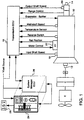
- Transmission 10 comprises a multiple ratio main transmission section connected in series with a multiple ratio auxiliary section.
- Transmission 10 includes an input shaft 12 driven by a prime mover such as a diesel engine E through a normally engaged, but selectively disengagable, friction master clutch C.
- the master clutch C has a driving portion connected to the engine crankshaft and a driven portion fixed to the transmission input shaft 12.
- the engine is fuel controlled by a manually operable throttle device (not shown) and the master clutch is manually controlled by a clutch pedal or the like (not shown).
- An input shaft brake B operated by overtravel depression of the clutch pedal, is preferably provided to permit quicker upshifting as is well known in the art.
- the transmission output shaft 14 is driven through the gearing of the transmission 10 at a speed which is reduced in relation to the transmission input shaft 12 by the ratio of the current gear selected.
- Shifting of the gears of the transmission 10 is under the control of an electronic control unit or ECU 16, preferably microprocessor based, which receives inputs from a number of sensors as indicated, including an input shaft sensor 18 and an output shaft sensor 20.
- the ECU 16 receives inputs from and provides control signals to an XY shifting mechanism 22 to effect gear shifts as described more fully in U.S. Pat. No. 4,873,881, assigned to the assignee of the present invention.
- the ECU 16 also receives inputs from and provides control signals to a shift console and display unit generally designated 24, either directly or as shown in Figure 1, over a data link coupling the ECU 16 to a system manager ECU 26 which directly interfaces with the console and display unit 24.
- the unit 24 provides status information to the driver and also includes Up and Down buttons for manually shifting the transmission when the console is in the Hold position H.
- a driver display module 28 may be provided to display current gear and may include arrows showing whether the shift was an upshift or a downshift. Further details regarding the transmission 10 and the system for controlling such a transmission may be obtained from the aforementioned U. S. Patent No. 5,109,721 as well as U. S. Pat. No. 5,050,079, and the patents referenced and discussed therein.
- FIGS 2a and 2b plots of transmission output speed as a function of input speed are shown for a 10 speed transmission of the type represented in Figure 1.
- an automatic upshift to the next gear is assumed to occur when the input shaft speed (engine speed) reaches 1600 rpm.
- an automatic downshift is assumed to occur when the engine speed drops to 1200 rpm.
- the engine speeds referenced here are by way of example only and may be different for other transmission configurations.
- the transmission output shaft speed ideally does not change in shifting from the present gear to the next higher or lower gear.
- the gear shift selection method of the present invention is depicted in a computer flow chart.
- a search indicated at 32, for a useable gear is initiated by examining a list or table of gears beginning with the first gear of the transmission and ending with the last gear "N" of the transmission.
- the first gear located during the search which is available for use, that is to say no fault exists that would prevent an upshift to the gear located, is tested against the criteria set out in decision blocks 36 and 38.
- the list of gears in the transmission may be contained in a lookup table with their associated gear ratios and may be appropriately identified as being available for use or not available for use based on whether a malfunction of a gear or sensor would make use of the gear unacceptable.
- the system may respond to a fault condition by entering a restricted mode of operation where the table is restricted to only those gears that are available for use i.e. the existing table would be replaced with a new table in the event of a failure so that only available gears are searched. In this case the decision block 34 would be unnecessary.
- each available gear located during the automatic upshift search is tested against the criteria of decision block 36 to determine if the engine speed that would result from using the gear located is less than or equal to a predetermined maximum such as for example 1570 rpm. If so, then the gear ratio is further tested against the criteria set out in decision block 38, otherwise the search is continued until the next available gear is located. If the engine speed that would result from using the gear located is not only less that the predetermined maximum as required by block 36, but is also greater than a predetermined minimum such as 900 rpm, then the shift to the selected gear is made as indicated at 40, otherwise the search is continued until a suitable gear is selected.
- a predetermined maximum such as for example 1570 rpm
- a determination of whether a downshift is required is made at decision block 42. If no downshift is required the routine is exited. If a downshift is required i.e. the engine speed (transmission input shaft speed) as detected by the input shaft speed sensor 18 drops below a predetermined minimum value such as, for example, 1200 rpm, then a search is initiated, as indicated at 44,46, through the list of gears in descending order from N to 1, to locate the next available gear. The engine speed that would result from using the next available gear is calculated by multiplying the existing output shaft speed by the gear ratio of the gear located.
Landscapes
- Engineering & Computer Science (AREA)
- General Engineering & Computer Science (AREA)
- Mechanical Engineering (AREA)
- Control Of Transmission Device (AREA)
- Gear-Shifting Mechanisms (AREA)
Claims (6)
- Une méthode exécutée par ordinateur pour changer les vitesses dans un système de transmission en réponse à une demande de changement de vitesse (30, 42), ledit système comportant une transmission (10) ayant plusieurs vitesses, ladite transmission étant accouplée d'une manière assurant la transmission de l'entraînement, par l'intermédiaire d'un embrayage débrayable (C), à un moteur (E), une unité de commande (16) agencée pour recevoir des signaux d'entrée de plusieurs détecteurs (18, 20, 22) indicatifs de l'état du système de transmission et pour traiter ces signaux conformément à des règles logiques et pour émettre en sortie des signaux de commande appliqués à au moins un actionneur (22) du système, ladite méthode étant caractérisée en ce qu'elle consiste :• à effectuer une recherche (32, 34) parmi les vitesses disponibles organisées dans un ordre prédéterminé en fonction du sens de la demande de changement de vitesse (30, 42) pour trouver une vitesse particulière parmi les vitesses disponibles qui soit susceptible d'être utilisée ;• à déterminer si la vitesse du moteur qui résulterait de l'utilisation de ladite vitesse satisfait aux critères qui consistent à être à la fois inférieure à une vitesse maximale prédéterminée du moteur (36, 50) et supérieure à une vitesse minimale prédéterminée du moteur (38, 48); et, si lesdits critères ne sont pas satisfaits, à continuer les étapes de recherche et de détermination jusqu'à ce qu'une vitesse satisfasse à ces conditions et, dans ce cas, à effectuer un changement (40, 52) de la vitesse actuelle à ladite vitesse particulière.
- La méthode de la revendication 1 dans laquelle l'étape servant à déterminer s'il est satisfait aux critères est caractérisée en ce qu'elle comporte, en outre, l'étape qui consiste :• à calculer la vitesse de sortie du moteur en multipliant la vitesse de sortie actuelle du moteur par un rapport qui correspond à ladite vitesse particulière divisé par un rapport correspondant à la vitesse actuelle.
- La méthode de la revendication 1, caractérisée en ce qu'elle comporte, en outre, l'étape qui consiste :• à détecter la présence de conditions indicatives d'une défaillance du système ; et• à répondre à la détection de la présence des conditions en entrant dans un mode de fonctionnement du système à nombre de vitesses limité pendant lequel un nombre de vitesses inférieur au nombre des vitesses disponibles est déterminé comme étant susceptible d'être utilisé.
- La méthode de la revendication 3 dans laquelle l'étape des recherche (32,44) est caractérisée en ce qu'elle comporte l'étape qui consiste :• à ne rechercher que les vitesses susceptibles d'être utilisées comme déterminé par l'étape de réponse.
- La méthode de la revendication 3 dans laquelle les vitesses utilisables sont organisées dans un ordre prédéterminé dans une table basées sur les rapports d'engrènement associés, la table étant mise en mémoire dans l'unité de commande, et dans laquelle l'étape de réponse est en outre caractérisée en ce qu'elle comporte l'étape qui consiste :• à créer une nouvelle table qui contient les vitesses qui ont été déterminées comme étant susceptibles d'être utilisées dans le mode de fonctionnement à nombre de vitesses limité.
- La méthode de la revendication 1 dans laquelle les vitesses disponibles sont organisées dans un ordre prédéterminé dans une table basée sur les rapports d'engrenages correspondants, la table étant mise en mémoire dans l'unité de commande et l'étape de recherche des vitesses disponibles comportant l'exécution d'une recherche dans la table.
Applications Claiming Priority (2)
| Application Number | Priority Date | Filing Date | Title |
|---|---|---|---|
| US07/968,200 US5323669A (en) | 1992-10-29 | 1992-10-29 | Fault tolerant method of transmission gear selection |
| US968200 | 1992-10-29 |
Publications (2)
| Publication Number | Publication Date |
|---|---|
| EP0595518A1 EP0595518A1 (fr) | 1994-05-04 |
| EP0595518B1 true EP0595518B1 (fr) | 1997-07-16 |
Family
ID=25513897
Family Applications (1)
| Application Number | Title | Priority Date | Filing Date |
|---|---|---|---|
| EP93308264A Expired - Lifetime EP0595518B1 (fr) | 1992-10-29 | 1993-10-18 | Méthode tolérant les fautes pour la sélection d'un rapport de vitesse |
Country Status (11)
| Country | Link |
|---|---|
| US (1) | US5323669A (fr) |
| EP (1) | EP0595518B1 (fr) |
| JP (1) | JP3458218B2 (fr) |
| KR (1) | KR100234787B1 (fr) |
| CN (1) | CN1040574C (fr) |
| AT (1) | ATE155560T1 (fr) |
| BR (1) | BR9304085A (fr) |
| CA (1) | CA2108947C (fr) |
| CZ (1) | CZ287847B6 (fr) |
| DE (1) | DE69312216T2 (fr) |
| ES (1) | ES2106287T3 (fr) |
Cited By (1)
| Publication number | Priority date | Publication date | Assignee | Title |
|---|---|---|---|---|
| DE102006007666A1 (de) * | 2006-02-18 | 2007-09-06 | Bayerische Motoren Werke Ag | Gangwechselsteuerung für Automatikgetriebe in Kraftfahrzeugen mit einem elektronischen Steuergerät |
Families Citing this family (24)
| Publication number | Priority date | Publication date | Assignee | Title |
|---|---|---|---|---|
| US5406861A (en) * | 1993-09-22 | 1995-04-18 | Eaton Corporation | Manual modification of automatic mode shift points |
| US5569115A (en) * | 1995-07-27 | 1996-10-29 | Rockwell International Corporation | Engine speed synchronization system for assisting in manual transmission shifting |
| US5582558A (en) * | 1995-07-27 | 1996-12-10 | Rockwell International Corporation | Combined system for assisting shifting of manual transmission |
| US5611245A (en) * | 1995-09-08 | 1997-03-18 | Case Corporation | Method and apparatus for controlling a power transmission to match vehicle ground speed |
| US5875410A (en) | 1996-01-12 | 1999-02-23 | Eaton Corporation | Dynamic best gear selection for automated transmission system |
| DE19625935A1 (de) * | 1996-06-28 | 1998-01-08 | Bosch Gmbh Robert | System zur Einstellung einer Getriebeübersetzung |
| GB9617956D0 (en) * | 1996-08-28 | 1996-10-09 | Eaton Corp | Downshift control method/system for vehicular automated mechanical transmission |
| US5875409A (en) * | 1997-02-05 | 1999-02-23 | Eaton Corporation | Transition to degraded mode of operation |
| JP2003148602A (ja) * | 2001-11-15 | 2003-05-21 | Toyota Motor Corp | 車両用有段変速機の変速制御装置 |
| JP4742578B2 (ja) * | 2003-12-19 | 2011-08-10 | 株式会社デンソー | 自動変速機の制御装置 |
| DE102009046342B4 (de) * | 2009-11-03 | 2022-09-29 | Zf Friedrichshafen Ag | Verfahren zum Betreiben eines Antriebsstrangs |
| CN102116369A (zh) * | 2010-07-22 | 2011-07-06 | 浙江吉利汽车研究院有限公司 | 自动变速器的手动换挡控制方法 |
| FR2963650B1 (fr) * | 2010-08-05 | 2013-04-12 | Renault Sa | Procede de reconnaissance et de gestion des rapports indisponibles d'une boite de vitesse automatique et systeme associe. |
| JP5873277B2 (ja) * | 2011-09-22 | 2016-03-01 | アイシン・エーアイ株式会社 | 車両の動力伝達制御装置 |
| KR101481239B1 (ko) | 2012-12-26 | 2015-01-09 | 현대자동차주식회사 | Amt 차량의 변속 제어방법 |
| CN104019216B (zh) * | 2014-05-14 | 2017-01-11 | 潍柴动力股份有限公司 | Amt选换挡执行机构的控制方法和装置 |
| CN104832640B (zh) * | 2014-07-29 | 2017-10-10 | 北汽福田汽车股份有限公司 | 故障下的车辆换挡控制方法、系统及具有其的车辆 |
| US9494232B2 (en) * | 2015-01-07 | 2016-11-15 | GM Global Technology Operations LLC | Method and apparatus for monitoring a transmission range selector |
| CN105370876B (zh) * | 2015-11-10 | 2018-08-28 | 中国北方车辆研究所 | 具有高速低速四驱功能的车辆amt换档控制方法 |
| CN111016881B (zh) * | 2019-12-06 | 2021-03-16 | 义乌吉利自动变速器有限公司 | 一种混合动力总成挡位控制系统及车辆 |
| CN112196994B (zh) | 2019-12-17 | 2022-03-15 | 长城汽车股份有限公司 | 两档减速箱档位控制方法及系统 |
| CN112460251B (zh) * | 2020-12-08 | 2022-06-14 | 安徽江淮汽车集团股份有限公司 | 柴油车辆及其档位识别方法和计算机可读存储介质 |
| CN115681480A (zh) * | 2022-10-24 | 2023-02-03 | 浙江吉利控股集团有限公司 | 档位控制方法、控制装置、车辆和存储介质 |
| CN120062347B (zh) * | 2024-11-04 | 2025-10-14 | 北京卡文新能源汽车有限公司 | 车辆的换挡控制方法和车辆 |
Citations (1)
| Publication number | Priority date | Publication date | Assignee | Title |
|---|---|---|---|---|
| EP0310275A2 (fr) * | 1987-09-28 | 1989-04-05 | SATURN CORPORATION (a Delaware corp.) | Modification du schéma de commutation en cas de défaillance pour une transmission, commandée électroniquement |
Family Cites Families (20)
| Publication number | Priority date | Publication date | Assignee | Title |
|---|---|---|---|---|
| FR2265568B1 (fr) * | 1974-03-26 | 1978-03-24 | Berliet Automobiles | |
| SE420295B (sv) * | 1980-11-28 | 1981-09-28 | Saab Scania Ab | Forfarande for automatiskt vexelval i en fordonstransmission |
| US4507736A (en) * | 1982-02-11 | 1985-03-26 | Wabco Fahrzeugbremsen Gmbh | Transmission gear shift control system |
| JPS5963230A (ja) * | 1982-10-04 | 1984-04-10 | Toyota Motor Corp | 車両の最適シフト時期表示装置 |
| JPS59106752A (ja) * | 1982-12-06 | 1984-06-20 | Mazda Motor Corp | 電子制御式自動変速機 |
| GB8418749D0 (en) * | 1984-07-23 | 1984-08-30 | Eaton Ltd | Semi-automatic transmission control |
| DE3429531A1 (de) * | 1984-08-10 | 1986-02-20 | Wabco Westinghouse Fahrzeugbremsen GmbH, 3000 Hannover | Hilfskraftbetaetigtes fahrzeuggetriebe |
| US4849899A (en) * | 1986-04-07 | 1989-07-18 | Eaton Corporation | Method for controlling AMT system including speed sensor signal fault detection and tolerance |
| US4922425A (en) * | 1986-04-18 | 1990-05-01 | Eaton Corporation | Method for controlling AMT system including throttle position sensor signal fault detection and tolerance |
| US5137104A (en) * | 1987-10-06 | 1992-08-11 | Nissan Motor Company, Limited | System and method for automatically controlling vehicle speed to desired cruise speed |
| GB8728837D0 (en) * | 1987-12-10 | 1988-01-27 | Eaton Corp | Semi-automatic mechanical transmission control and control and control method |
| JPH07109243B2 (ja) * | 1988-01-25 | 1995-11-22 | 日産自動車株式会社 | 自動変速機の変速制御装置 |
| US4873881A (en) * | 1989-01-06 | 1989-10-17 | Eaton Corporation | Electrically actuated x-y shifting mechanism |
| GB8906918D0 (en) * | 1989-03-28 | 1989-05-10 | Eaton Corp | Method for upshifting a compound semi-blocked splitter type automatic mechanical transmission |
| JPH0356757A (ja) * | 1989-07-24 | 1991-03-12 | Zexel Corp | 自動変速装置 |
| US5165307A (en) * | 1990-04-26 | 1992-11-24 | Dickey-John Corporation | Transmission controller |
| IT1240391B (it) * | 1990-07-10 | 1993-12-10 | Iveco Fiat | Gruppo motopropulsore automatizzato per un veicolo industriale. |
| US5148722A (en) * | 1990-08-17 | 1992-09-22 | Chrysler Corporation | Method for invoking a shutdown on default |
| US5109729A (en) * | 1991-05-09 | 1992-05-05 | Eaton Corporation | Throttle control fault detection and tolerance method/system |
| US5109721A (en) * | 1991-05-09 | 1992-05-05 | Eaton Corporation | Range shifting only fault tolerance method/system |
-
1992
- 1992-10-29 US US07/968,200 patent/US5323669A/en not_active Expired - Fee Related
-
1993
- 1993-10-18 DE DE69312216T patent/DE69312216T2/de not_active Expired - Fee Related
- 1993-10-18 AT AT93308264T patent/ATE155560T1/de not_active IP Right Cessation
- 1993-10-18 ES ES93308264T patent/ES2106287T3/es not_active Expired - Lifetime
- 1993-10-18 EP EP93308264A patent/EP0595518B1/fr not_active Expired - Lifetime
- 1993-10-21 CA CA002108947A patent/CA2108947C/fr not_active Expired - Fee Related
- 1993-10-22 KR KR1019930022007A patent/KR100234787B1/ko not_active Expired - Fee Related
- 1993-10-27 CZ CZ19932290A patent/CZ287847B6/cs not_active IP Right Cessation
- 1993-10-29 BR BR9304085A patent/BR9304085A/pt not_active IP Right Cessation
- 1993-10-29 CN CN93120389A patent/CN1040574C/zh not_active Expired - Fee Related
- 1993-10-29 JP JP29404793A patent/JP3458218B2/ja not_active Expired - Fee Related
Patent Citations (1)
| Publication number | Priority date | Publication date | Assignee | Title |
|---|---|---|---|---|
| EP0310275A2 (fr) * | 1987-09-28 | 1989-04-05 | SATURN CORPORATION (a Delaware corp.) | Modification du schéma de commutation en cas de défaillance pour une transmission, commandée électroniquement |
Cited By (2)
| Publication number | Priority date | Publication date | Assignee | Title |
|---|---|---|---|---|
| DE102006007666A1 (de) * | 2006-02-18 | 2007-09-06 | Bayerische Motoren Werke Ag | Gangwechselsteuerung für Automatikgetriebe in Kraftfahrzeugen mit einem elektronischen Steuergerät |
| DE102006007666B4 (de) * | 2006-02-18 | 2020-07-16 | Bayerische Motoren Werke Aktiengesellschaft | Gangwechselsteuerung für Automatikgetriebe in Kraftfahrzeugen mit einem elektronischen Steuergerät |
Also Published As
| Publication number | Publication date |
|---|---|
| DE69312216D1 (de) | 1997-08-21 |
| DE69312216T2 (de) | 1998-02-12 |
| US5323669A (en) | 1994-06-28 |
| CA2108947C (fr) | 2000-07-18 |
| EP0595518A1 (fr) | 1994-05-04 |
| CN1093323A (zh) | 1994-10-12 |
| ES2106287T3 (es) | 1997-11-01 |
| CA2108947A1 (fr) | 1994-04-30 |
| JP3458218B2 (ja) | 2003-10-20 |
| BR9304085A (pt) | 1994-05-03 |
| CN1040574C (zh) | 1998-11-04 |
| KR100234787B1 (ko) | 2000-03-02 |
| KR940009555A (ko) | 1994-05-20 |
| CZ287847B6 (en) | 2001-02-14 |
| CZ229093A3 (en) | 1994-05-18 |
| ATE155560T1 (de) | 1997-08-15 |
| JPH06201036A (ja) | 1994-07-19 |
Similar Documents
| Publication | Publication Date | Title |
|---|---|---|
| EP0595518B1 (fr) | Méthode tolérant les fautes pour la sélection d'un rapport de vitesse | |
| US4523281A (en) | Automatic transmission controller for automobiles | |
| CN1068550C (zh) | 自适应换档控制方法/系统 | |
| KR900006593B1 (ko) | 자동변속기의 변속 제어장치 | |
| US4848529A (en) | Automatic transmission system | |
| EP0273735B1 (fr) | Système de commande électronique pour transmission automatique | |
| US5761628A (en) | Start gear ratio control system and method utilizing the highest allowable start gear ratio | |
| US6149545A (en) | Automated transmission upshift control | |
| EP1020664B1 (fr) | Méthode de commande de rétrogradation d'une boíte de vitesses automatisée | |
| US5517411A (en) | Neutral attainment control system/method for controlling shifting in vehicular automated mechanical transmission systems | |
| EP0128471B1 (fr) | Dispositif de commande d'une transmission automatique d'un véhicule | |
| EP0128470B1 (fr) | Dispositif de commande d'une transmission automatique d'un véhicule | |
| JPH0362940B2 (fr) | ||
| EP0175982A1 (fr) | Commande de la transmission automatique d'un véhicule | |
| EP0246035B1 (fr) | Procédé de commande de système de transmission mécanique automatique comportant la commande de combustion après le changement de boîte de transmission | |
| EP1070880B1 (fr) | Commande adaptative de passages descendant des rapports d'une boíte de vitesses automatisée | |
| CN100357638C (zh) | 检测自动变速系统中伪空档的方法 | |
| EP0065824B1 (fr) | Système de commande pour une boîte de vitesse automatique | |
| JP2811914B2 (ja) | トルクコンバータ付き車両の自動変速制御装置 | |
| JPS61116160A (ja) | 車両用電子制御式自動変速機の変速制御方法 | |
| JPH04171355A (ja) | 自動変速機の制御装置 | |
| JPH08261320A (ja) | 車両の変速制御装置 |
Legal Events
| Date | Code | Title | Description |
|---|---|---|---|
| PUAI | Public reference made under article 153(3) epc to a published international application that has entered the european phase |
Free format text: ORIGINAL CODE: 0009012 |
|
| AK | Designated contracting states |
Kind code of ref document: A1 Designated state(s): AT DE ES FR GB IT NL SE |
|
| 17P | Request for examination filed |
Effective date: 19940701 |
|
| 17Q | First examination report despatched |
Effective date: 19950828 |
|
| GRAG | Despatch of communication of intention to grant |
Free format text: ORIGINAL CODE: EPIDOS AGRA |
|
| GRAH | Despatch of communication of intention to grant a patent |
Free format text: ORIGINAL CODE: EPIDOS IGRA |
|
| GRAH | Despatch of communication of intention to grant a patent |
Free format text: ORIGINAL CODE: EPIDOS IGRA |
|
| GRAH | Despatch of communication of intention to grant a patent |
Free format text: ORIGINAL CODE: EPIDOS IGRA |
|
| GRAA | (expected) grant |
Free format text: ORIGINAL CODE: 0009210 |
|
| AK | Designated contracting states |
Kind code of ref document: B1 Designated state(s): AT DE ES FR GB IT NL SE |
|
| REF | Corresponds to: |
Ref document number: 155560 Country of ref document: AT Date of ref document: 19970815 Kind code of ref document: T |
|
| REF | Corresponds to: |
Ref document number: 69312216 Country of ref document: DE Date of ref document: 19970821 |
|
| ET | Fr: translation filed | ||
| ITF | It: translation for a ep patent filed | ||
| REG | Reference to a national code |
Ref country code: ES Ref legal event code: FG2A Ref document number: 2106287 Country of ref document: ES Kind code of ref document: T3 |
|
| PLBE | No opposition filed within time limit |
Free format text: ORIGINAL CODE: 0009261 |
|
| 26N | No opposition filed | ||
| REG | Reference to a national code |
Ref country code: GB Ref legal event code: IF02 |
|
| PGFP | Annual fee paid to national office [announced via postgrant information from national office to epo] |
Ref country code: FR Payment date: 20041004 Year of fee payment: 12 |
|
| PGFP | Annual fee paid to national office [announced via postgrant information from national office to epo] |
Ref country code: SE Payment date: 20041005 Year of fee payment: 12 |
|
| PGFP | Annual fee paid to national office [announced via postgrant information from national office to epo] |
Ref country code: ES Payment date: 20041026 Year of fee payment: 12 |
|
| PGFP | Annual fee paid to national office [announced via postgrant information from national office to epo] |
Ref country code: DE Payment date: 20041029 Year of fee payment: 12 |
|
| PGFP | Annual fee paid to national office [announced via postgrant information from national office to epo] |
Ref country code: GB Payment date: 20050914 Year of fee payment: 13 Ref country code: AT Payment date: 20050914 Year of fee payment: 13 |
|
| PGFP | Annual fee paid to national office [announced via postgrant information from national office to epo] |
Ref country code: NL Payment date: 20050916 Year of fee payment: 13 |
|
| PG25 | Lapsed in a contracting state [announced via postgrant information from national office to epo] |
Ref country code: IT Free format text: LAPSE BECAUSE OF NON-PAYMENT OF DUE FEES;WARNING: LAPSES OF ITALIAN PATENTS WITH EFFECTIVE DATE BEFORE 2007 MAY HAVE OCCURRED AT ANY TIME BEFORE 2007. THE CORRECT EFFECTIVE DATE MAY BE DIFFERENT FROM THE ONE RECORDED. Effective date: 20051018 |
|
| PG25 | Lapsed in a contracting state [announced via postgrant information from national office to epo] |
Ref country code: SE Free format text: LAPSE BECAUSE OF NON-PAYMENT OF DUE FEES Effective date: 20051019 Ref country code: ES Free format text: LAPSE BECAUSE OF NON-PAYMENT OF DUE FEES Effective date: 20051019 |
|
| PG25 | Lapsed in a contracting state [announced via postgrant information from national office to epo] |
Ref country code: DE Free format text: LAPSE BECAUSE OF NON-PAYMENT OF DUE FEES Effective date: 20060503 |
|
| EUG | Se: european patent has lapsed | ||
| PG25 | Lapsed in a contracting state [announced via postgrant information from national office to epo] |
Ref country code: FR Free format text: LAPSE BECAUSE OF NON-PAYMENT OF DUE FEES Effective date: 20060630 |
|
| PG25 | Lapsed in a contracting state [announced via postgrant information from national office to epo] |
Ref country code: AT Free format text: LAPSE BECAUSE OF NON-PAYMENT OF DUE FEES Effective date: 20061018 |
|
| REG | Reference to a national code |
Ref country code: FR Ref legal event code: ST Effective date: 20060630 |
|
| REG | Reference to a national code |
Ref country code: ES Ref legal event code: FD2A Effective date: 20051019 |
|
| PG25 | Lapsed in a contracting state [announced via postgrant information from national office to epo] |
Ref country code: NL Free format text: LAPSE BECAUSE OF NON-PAYMENT OF DUE FEES Effective date: 20070501 |
|
| GBPC | Gb: european patent ceased through non-payment of renewal fee |
Effective date: 20061018 |
|
| NLV4 | Nl: lapsed or anulled due to non-payment of the annual fee |
Effective date: 20070501 |
|
| PG25 | Lapsed in a contracting state [announced via postgrant information from national office to epo] |
Ref country code: GB Free format text: LAPSE BECAUSE OF NON-PAYMENT OF DUE FEES Effective date: 20061018 |