EP0595586A2 - Verfahren zur Steuerung des Lüft-Kraftstoffverhältnisses in einer Innenbrennkraftmaschine - Google Patents
Verfahren zur Steuerung des Lüft-Kraftstoffverhältnisses in einer Innenbrennkraftmaschine Download PDFInfo
- Publication number
- EP0595586A2 EP0595586A2 EP93308494A EP93308494A EP0595586A2 EP 0595586 A2 EP0595586 A2 EP 0595586A2 EP 93308494 A EP93308494 A EP 93308494A EP 93308494 A EP93308494 A EP 93308494A EP 0595586 A2 EP0595586 A2 EP 0595586A2
- Authority
- EP
- European Patent Office
- Prior art keywords
- catalyst
- exhaust gas
- gas oxygen
- engine
- fuel ratio
- Prior art date
- Legal status (The legal status is an assumption and is not a legal conclusion. Google has not performed a legal analysis and makes no representation as to the accuracy of the status listed.)
- Granted
Links
Images

Classifications
-
- F—MECHANICAL ENGINEERING; LIGHTING; HEATING; WEAPONS; BLASTING
- F02—COMBUSTION ENGINES; HOT-GAS OR COMBUSTION-PRODUCT ENGINE PLANTS
- F02D—CONTROLLING COMBUSTION ENGINES
- F02D41/00—Electrical control of supply of combustible mixture or its constituents
- F02D41/02—Circuit arrangements for generating control signals
- F02D41/14—Introducing closed-loop corrections
- F02D41/1438—Introducing closed-loop corrections using means for determining characteristics of the combustion gases; Sensors therefor
- F02D41/1439—Introducing closed-loop corrections using means for determining characteristics of the combustion gases; Sensors therefor characterised by the position of the sensor
- F02D41/1441—Plural sensors
-
- F—MECHANICAL ENGINEERING; LIGHTING; HEATING; WEAPONS; BLASTING
- F02—COMBUSTION ENGINES; HOT-GAS OR COMBUSTION-PRODUCT ENGINE PLANTS
- F02D—CONTROLLING COMBUSTION ENGINES
- F02D41/00—Electrical control of supply of combustible mixture or its constituents
- F02D41/02—Circuit arrangements for generating control signals
- F02D41/14—Introducing closed-loop corrections
- F02D41/1438—Introducing closed-loop corrections using means for determining characteristics of the combustion gases; Sensors therefor
- F02D41/1477—Introducing closed-loop corrections using means for determining characteristics of the combustion gases; Sensors therefor characterised by the regulation circuit or part of it,(e.g. comparator, PI regulator, output)
-
- F—MECHANICAL ENGINEERING; LIGHTING; HEATING; WEAPONS; BLASTING
- F02—COMBUSTION ENGINES; HOT-GAS OR COMBUSTION-PRODUCT ENGINE PLANTS
- F02D—CONTROLLING COMBUSTION ENGINES
- F02D41/00—Electrical control of supply of combustible mixture or its constituents
- F02D41/02—Circuit arrangements for generating control signals
- F02D41/14—Introducing closed-loop corrections
- F02D41/1438—Introducing closed-loop corrections using means for determining characteristics of the combustion gases; Sensors therefor
- F02D41/1486—Introducing closed-loop corrections using means for determining characteristics of the combustion gases; Sensors therefor with correction for particular operating conditions
- F02D41/1488—Inhibiting the regulation
- F02D41/1489—Replacing of the control value by a constant
Definitions
- This invention relates to electronic engine control of internal combustion engines.
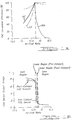
- Fig. 1A and 1B show catalyst conversion efficiency and EGO sensor output voltage versus A/F irrespectively for sensors located both in front of and behind a typical catalyst.
- the switch point of the pre-catalyst EGO sensor does not coincide exactly with the catalyst window, whereas the switch point of the post-catalyst sensor generally does.
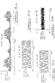
- Figs. 2A and 2B show plots of post-catalyst EGO sensor output voltage versus time obtained when the engine was operated under closed-loop A/F control using conventional low-gain integral feedback from the post-catalyst EGO sensor.
- the EGO sensor output voltage shows an erratic low-frequency oscillation of approximately 0.024 Hertz
- the sensor output voltage shows a well-defined oscillation of approximately 0.015 Hertz.
- amethod for controlling air/fuel ratio of an internal combustion engine controlled by an electronic engine control and having an exhaust gas oxygen (EGO) sensor positioned in an exhaust stream flow from the engine said method including the step of utilizing different air/fuel ratio feedback control strategies depending upon whether the exhaust gas oxygen sensor is saturated, rich or lean, or operating in a linear region.
- EGO exhaust gas oxygen
- a structure in accordance with an embodiment of this invention prevents low-frequency oscillations, such as described above, from occurring with post-catalyst A/F feedback systems.
- the feedback signal When the EGO sensor output voltage indicates a rich condition (V out > 0.7 volts, for example), the feedback signal would be a linear ramp which slowly leans out the engine A/F as a function of time. When the EGO sensor output voltage indicates a lean condition (V out ⁇ 0.15 volts, for example), the feedback signal would be a linear ramp which slowly enriches the engine A/F as a function of time. When the EGO sensor voltage is between the rich and lean limits, the feedback signal would be proportional to the difference between the output of the EGO sensor and an appropriate reference voltage such as 0.45 volts.
- the output of the EGO sensor is essentially saturated at a "high" output voltage and does not give any meaningful information as to how much the engine A/F is rich of stoichiometry (See Figs. 1A and 1B).
- the feedback strategy in this case is to simply ramp the engine A/F back toward stoichiometry until the sensor output voltage starts to switch toward its lean state.
- the rate at which the feedback signal commands the engine A/F toward stoichiometry must be restricted to a very low value. This is necessary so that the A/F won't pass through stoichiometry faster than the EGO sensor can detect and subsequently hold it in the window of the catalyst.
- the A/F ramp rate can be automatically adjusted to provide the fastest possible feedback correction without causing unstable system operation.
- This automatic rate control could be implemented by periodically increasing the A/F ramp rate until the system begins to oscillate in a well defined limit-cycle, and then reducing the ramp rate by an appropriate amount.
- the time delay through the engine will be a function of rpm (and torque).
- the optimum value for the ramp rate will therefore be a function of engine rpm (and torque), and will be contained in an appropriate table in the engine control computer.
- the output voltage of the EGO sensor will be approximately linearly related to A/F as suggested by the post-catalyst EGO sensor plot shown in Fig. 1B. Since the EGO sensor output voltage in this case does provide information as to how far the engine A/F is away from stoichiometry, the strategy is to feed back a signal that is proportional to the difference between the output of the EGO sensor and a suitable reference voltage such as 0.45 volts.
- the value of the proportional feedback gain must be kept to a low value so that the feedback system will not become unstable and oscillate.
- the gain should be high enough to correct possible A/F disturbances as fast as possible without causing oscillations. In some applications where the need to provide oscillations is paramount, the gain might be reduced to zero so that the linear region effectively becomes a dead band.
- the value of the gain used for this integral feedback would be chosen to be sufficiently high to eliminate steady-state errors, but not too high to cause unstable (i.e., oscillatory) operation.
- the output of the EGO sensor is essentially saturated at a low output voltage and does not give any meaningful information as to how much the engine A/F is lean of stoichiometry (See Fig. 1B).
- the feedback strategy in this case is to simply ramp the engine A/F back toward stoichiometry until the sensor output voltage starts to switch toward its rich state. This is the same strategy that was used when the engine was operating on the rich side of the catalyst window except now the engine A/F is ramped rich rather than lean.
- the rate at which the feedback signal ramps the engine A/F toward stoichiometry must be restricted to a very low value so that the A/F won't pass through stoichiometry faster than the EGO sensor can detect and subsequently hold it in the window of the catalyst.
- the ramp rate of the A/F feedback signal could be automatically adjusted to provide the fastest possible feedback correction without causing system oscillation.
- the optimal ramp rate will be a function of engine rpm (and torque), and will be contained in an appropriate table in the engine control computer.
- a tri-state control method in accordance with an embodiment of this invention, can be applied to a system with pre-catalyst and post-catalyst A/F feedback to eliminate erratic oscillations.
- An example of the invention's ability to eliminate low-frequency oscillations is presented in Figs. 3A and 3B which show the post-catalyst EGO sensor output voltages versus time for a pure integral post-catalyst A/F feedback controller (Fig. 3A) and for this tri-state controller (Fig. 3B).
- the low-frequency oscillation that occurs with the pure integral feedback is eliminated when tri-state feedback is used.
- An embodiment of this invention can also be used to enhance the operation of certain catalyst monitoring schemes.
- the tri-state A/F post-catalyst feedback system can be used to enhance the catalyst monitoring scheme by providing a more uniform A/F versus time characteristic.
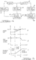
- an engine 41 has an exhaust stream coupled to a catalyst 42.
- a pre-catalyst EGO sensor 43 is positioned upstream of catalyst 42 and a post-catalyst EGO sensor 44 is positioned downstream of catalyst 42.
- a post feedback controller 46 receives a signal from sensor 44 and provides an air/fuel ratio trim signal to a pre-catalyst feedback controller 45 which also receives a signal from sensor 43.
- the output of feedback controller 45 is applied to a base fuel controller 47 which provides a fuel control signal to engine 41.
- a post-catalyst tri-state A/F controller can be combined with a pre-catalyst A/F controller in order to realize the high-frequency correction capabilities of the pre-catalyst feedback loop.
- Post-catalyst A/F feedback controller 46 serves as a trim for pre-catalyst A/F feedback controller 45.
- the A/F trim will maintain post-catalyst EGO sensor 44 at stoichiometry by appropriately changing the "dc" value of the pre-catalyst feedback loop. It should be noted that the actual A/F trim can be accomplished in one of several different ways.
- the feedback signal from post-catalyst A/F controller 46 can be used to change the switch point of pre-catalyst EGO sensor 43.
- the feedback signal from post-catalyst controller 46 can be used to change the relative values of the up-down integration rates and/or the jump back in pre-catalyst controller 45.
- the tri-state control method can be applied to the control of any A/F feedback loop utilizing an EGO sensor. As such, it can be directly applied to the pre-catalyst feedback loop as well as the post-catalyst feedback loop. Using tri-state control in the pre-catalyst feedback loop can eliminate the limit-cycle mode of operation normally associated with the pre-catalyst feedback loop.
- the EGO sensor would initially see a lean A/F, and its output would be approximately equal to 0.1 volts.
- the A/F feedback controller would slowly ramp the A/F richer until the engine A/F reached the linear region of the EGO sensor.
- the feedback controller would switch from a simple ramping mode to a proportional (or proportional plus integral) feedback mode, and the controller would drive the engine A/F to the pre-programmed setpoint. Assuming there would no other changes, the engine A/F would remain at this point.
- Idealized waveforms of the engine A/F, the EGO sensor output, and the feedback control signal corresponding to this situation are shown in Figures 6A, 6B, 6C as a function of time.
Landscapes
- Engineering & Computer Science (AREA)
- Chemical & Material Sciences (AREA)
- Combustion & Propulsion (AREA)
- Mechanical Engineering (AREA)
- General Engineering & Computer Science (AREA)
- Electrical Control Of Air Or Fuel Supplied To Internal-Combustion Engine (AREA)
Applications Claiming Priority (2)
| Application Number | Priority Date | Filing Date | Title |
|---|---|---|---|
| US968937 | 1992-10-30 | ||
| US07/968,937 US5282360A (en) | 1992-10-30 | 1992-10-30 | Post-catalyst feedback control |
Publications (3)
| Publication Number | Publication Date |
|---|---|
| EP0595586A2 true EP0595586A2 (de) | 1994-05-04 |
| EP0595586A3 EP0595586A3 (en) | 1994-09-07 |
| EP0595586B1 EP0595586B1 (de) | 1996-11-20 |
Family
ID=25514963
Family Applications (1)
| Application Number | Title | Priority Date | Filing Date |
|---|---|---|---|
| EP93308494A Expired - Lifetime EP0595586B1 (de) | 1992-10-30 | 1993-10-25 | Verfahren zur Steuerung des Luft-Kraftstoffverhältnisses in einer Innenbrennkraftmaschine |
Country Status (4)
| Country | Link |
|---|---|
| US (1) | US5282360A (de) |
| EP (1) | EP0595586B1 (de) |
| JP (1) | JP2958224B2 (de) |
| DE (1) | DE69306084T2 (de) |
Cited By (6)
| Publication number | Priority date | Publication date | Assignee | Title |
|---|---|---|---|---|
| DE4427328A1 (de) * | 1993-09-07 | 1995-03-09 | Ford Werke Ag | Verfahren zur Regelung des Luft-/Kraftstoffverhältnisses |
| GB2285520A (en) * | 1994-01-10 | 1995-07-12 | Ford Motor Co | Engine air/fuel control |
| EP0694684A3 (de) * | 1994-07-19 | 1996-09-11 | Magneti Marelli Spa | Elektronisches Gaskonzentrationssteuerungssystem |
| EP0694685A3 (de) * | 1994-07-19 | 1996-09-18 | Magneti Marelli Spa | Elektronisches Gaskonzentrationssteuerungssystem |
| FR2746851A1 (fr) * | 1996-03-27 | 1997-10-03 | Siemens Automotive Sa | Procede et dispositif de regulation en boucle fermee de la richesse d'un melange air/carburant destine a l'alimentation d'un moteur a combustion interne |
| EP1122415A3 (de) * | 2000-02-02 | 2003-10-29 | Delphi Technologies, Inc. | Verfahren zum Einstellen des Luft-Kraftstoff-Verhältnisses bei einem Verbrennungsmotor |
Families Citing this family (21)
| Publication number | Priority date | Publication date | Assignee | Title |
|---|---|---|---|---|
| IT1257100B (it) * | 1992-09-14 | 1996-01-05 | Fiat Auto Spa | Sistema di monitoraggio dell'efficienza di un catalizzatore, particolarmente per autoveicoli. |
| US5392598A (en) * | 1993-10-07 | 1995-02-28 | General Motors Corporation | Internal combustion engine air/fuel ratio regulation |
| US6301880B1 (en) | 2000-01-20 | 2001-10-16 | Ford Global Technologies, Inc. | Method and system for controlling air/fuel level for internal combustion engine with two exhaust banks |
| US6276129B1 (en) | 2000-01-20 | 2001-08-21 | Ford Global Technologies, Inc. | Method for controlling air/fuel mixture in an internal combustion engine |
| US6354077B1 (en) | 2000-01-20 | 2002-03-12 | Ford Global Technologies, Inc. | Method and system for controlling air/fuel level in two-bank exhaust system |
| DE60105661T2 (de) | 2000-01-20 | 2005-02-10 | Ford Global Technologies, Inc., Dearborn | Diagnosesystem zur Überwachung der Funktionsfähigkeit eines Katalysators unter Verwendung eines Bogenlängen-Verhältnisses |
| US6282888B1 (en) | 2000-01-20 | 2001-09-04 | Ford Technologies, Inc. | Method and system for compensating for degraded pre-catalyst oxygen sensor in a two-bank exhaust system |
| US6467254B1 (en) | 2000-01-20 | 2002-10-22 | Ford Global Technologies, Inc. | Diagnostic system for detecting catalyst failure using switch ratio |
| US6453665B1 (en) | 2000-04-28 | 2002-09-24 | Ford Global Technologies, Inc. | Catalyst based adaptive fuel control |
| US6363715B1 (en) | 2000-05-02 | 2002-04-02 | Ford Global Technologies, Inc. | Air/fuel ratio control responsive to catalyst window locator |
| US6588200B1 (en) | 2001-02-14 | 2003-07-08 | Ford Global Technologies, Llc | Method for correcting an exhaust gas oxygen sensor |
| US6622476B2 (en) | 2001-02-14 | 2003-09-23 | Ford Global Technologies, Llc | Lean NOx storage estimation based on oxygen concentration corrected for water gas shift reaction |
| US6629409B2 (en) * | 2001-06-20 | 2003-10-07 | Ford Global Technologies, Llc | System and method for determining set point location for oxidant-based engine air/fuel control strategy |
| US6497093B1 (en) * | 2001-06-20 | 2002-12-24 | Ford Global Technologies, Inc. | System and method for adjusting air-fuel ratio |
| US6453662B1 (en) * | 2001-06-20 | 2002-09-24 | Ford Global Technologies, Inc. | System and method for estimating oxidant storage of a catalyst |
| US6470675B1 (en) * | 2001-06-20 | 2002-10-29 | Ford Global Technologies, Inc. | System and method controlling engine based on predicated engine operating conditions |
| GB2391324B (en) * | 2002-07-29 | 2004-07-14 | Visteon Global Tech Inc | Open loop fuel controller |
| US6840036B2 (en) * | 2002-08-30 | 2005-01-11 | Ford Global Technologies, Llc | Control of oxygen storage in a catalytic converter |
| US6945033B2 (en) * | 2003-06-26 | 2005-09-20 | Ford Global Technologies, Llc | Catalyst preconditioning method and system |
| US7197866B2 (en) * | 2003-11-10 | 2007-04-03 | Ford Global Technologies, Llc | Control approach for use with dual mode oxygen sensor |
| JP5293889B2 (ja) * | 2010-05-28 | 2013-09-18 | トヨタ自動車株式会社 | 内燃機関の空燃比制御装置 |
Family Cites Families (32)
| Publication number | Priority date | Publication date | Assignee | Title |
|---|---|---|---|---|
| DE2442229C3 (de) * | 1974-09-04 | 1980-08-21 | Robert Bosch Gmbh, 7000 Stuttgart | Kraftstoffeinspritzanlage für eine Brennkraftmaschine |
| JPS5228934B2 (de) * | 1974-11-01 | 1977-07-29 | ||
| US4210106A (en) * | 1975-10-13 | 1980-07-01 | Robert Bosch Gmbh | Method and apparatus for regulating a combustible mixture |
| JPS52114823A (en) * | 1976-03-24 | 1977-09-27 | Nissan Motor Co Ltd | Air fuel ratio controller |
| JPS52145223U (de) * | 1976-04-30 | 1977-11-04 | ||
| US4191151A (en) * | 1978-03-20 | 1980-03-04 | General Motors Corporation | Oxygen sensor signal processing circuit for a closed loop air/fuel mixture controller |
| US4241710A (en) * | 1978-06-22 | 1980-12-30 | The Bendix Corporation | Closed loop system |
| JPS5535181A (en) * | 1978-09-05 | 1980-03-12 | Nippon Denso Co Ltd | Air fuel ratio control device |
| JPS5623551A (en) * | 1979-08-02 | 1981-03-05 | Fuji Heavy Ind Ltd | Air-fuel ratio controller |
| JPS56141035A (en) * | 1980-04-07 | 1981-11-04 | Nippon Denso Co Ltd | Air to fuel ratio control device |
| JPS5732036A (en) * | 1980-08-05 | 1982-02-20 | Honda Motor Co Ltd | Air/fuel ratio feedback control device for internal combustion engine |
| US4350130A (en) * | 1980-08-27 | 1982-09-21 | Ford Motor Company | Air fuel mixture control system and method |
| DE3214059A1 (de) * | 1981-05-20 | 1982-12-09 | Robert Bosch Gmbh, 7000 Stuttgart | Kraftstoffzumesssystem fuer eine brennkraftmaschine |
| JPS585445A (ja) * | 1981-07-01 | 1983-01-12 | Mitsubishi Electric Corp | 内燃機関のフイ−ドバツク燃料制御装置 |
| JPS5827857A (ja) * | 1981-08-12 | 1983-02-18 | Mitsubishi Electric Corp | 空燃比制御方法 |
| DE3231122C2 (de) * | 1982-08-21 | 1994-05-11 | Bosch Gmbh Robert | Regeleinrichtung für die Gemischzusammensetzung einer Brennkraftmaschine |
| JPS6079132A (ja) * | 1983-10-04 | 1985-05-04 | Mitsubishi Electric Corp | 機関の空燃比制御装置 |
| DE3408635A1 (de) * | 1984-03-09 | 1985-09-12 | Robert Bosch Gmbh, 7000 Stuttgart | Lambda-geregeltes gemischzumesssystem fuer eine brennkraftmaschine |
| JPS61169635A (ja) * | 1985-01-23 | 1986-07-31 | Hitachi Ltd | 空燃比制御方法 |
| US4744344A (en) * | 1985-02-20 | 1988-05-17 | Fuji Jukogyo Kabushiki Kaisha | System for compensating an oxygen sensor in an emission control system |
| JPH07113336B2 (ja) * | 1985-04-09 | 1995-12-06 | トヨタ自動車株式会社 | 内燃機関の空燃比制御装置 |
| US4625698A (en) * | 1985-08-23 | 1986-12-02 | General Motors Corporation | Closed loop air/fuel ratio controller |
| JPS62247142A (ja) * | 1986-04-18 | 1987-10-28 | Nissan Motor Co Ltd | 内燃機関の空燃比制御装置 |
| JP2570265B2 (ja) * | 1986-07-26 | 1997-01-08 | トヨタ自動車株式会社 | 内燃機関の空燃比制御装置 |
| US4881368A (en) * | 1987-02-09 | 1989-11-21 | Toyota Jidosha Kabushiki Kaisha | Double air-fuel ratio sensor system having improved exhaust emission characteristics |
| US4926826A (en) * | 1987-08-31 | 1990-05-22 | Japan Electronic Control Systems Co., Ltd. | Electric air-fuel ratio control apparatus for use in internal combustion engine |
| JPS6460744A (en) * | 1987-08-31 | 1989-03-07 | Honda Motor Co Ltd | Air-fuel ratio feedback control method for internal combustion engine |
| JP2801596B2 (ja) * | 1987-11-05 | 1998-09-21 | 日本特殊陶業株式会社 | 空燃比制御方法 |
| KR930011560B1 (ko) * | 1988-11-01 | 1993-12-11 | 미쓰비시 지도샤 고교 가부시끼가이샤 | 내연기관용 배기가스 정화장치 |
| US5094208A (en) * | 1988-12-10 | 1992-03-10 | Robert Bosch Gmbh | Fuel control system |
| US5069035A (en) * | 1989-10-26 | 1991-12-03 | Toyota Jidosha Kabushiki Kaisha | Misfire detecting system in double air-fuel ratio sensor system |
| JPH0833127B2 (ja) * | 1990-05-01 | 1996-03-29 | 株式会社ユニシアジェックス | 内燃機関の空燃比制御装置 |
-
1992
- 1992-10-30 US US07/968,937 patent/US5282360A/en not_active Expired - Lifetime
-
1993
- 1993-10-25 EP EP93308494A patent/EP0595586B1/de not_active Expired - Lifetime
- 1993-10-25 DE DE69306084T patent/DE69306084T2/de not_active Expired - Fee Related
- 1993-10-29 JP JP5272588A patent/JP2958224B2/ja not_active Expired - Fee Related
Cited By (11)
| Publication number | Priority date | Publication date | Assignee | Title |
|---|---|---|---|---|
| DE4427328A1 (de) * | 1993-09-07 | 1995-03-09 | Ford Werke Ag | Verfahren zur Regelung des Luft-/Kraftstoffverhältnisses |
| DE4427328C2 (de) * | 1993-09-07 | 1998-08-27 | Ford Werke Ag | Verfahren zur Regelung des Luft-/Kraftstoffverhältnisses |
| GB2285520A (en) * | 1994-01-10 | 1995-07-12 | Ford Motor Co | Engine air/fuel control |
| GB2285520B (en) * | 1994-01-10 | 1998-03-25 | Ford Motor Co | Engine air/fuel control method |
| EP0694684A3 (de) * | 1994-07-19 | 1996-09-11 | Magneti Marelli Spa | Elektronisches Gaskonzentrationssteuerungssystem |
| EP0694685A3 (de) * | 1994-07-19 | 1996-09-18 | Magneti Marelli Spa | Elektronisches Gaskonzentrationssteuerungssystem |
| US5637276A (en) * | 1994-07-19 | 1997-06-10 | MAGNETI MARELLI S.p.A. | Electronic concentration control system |
| US5697214A (en) * | 1994-07-19 | 1997-12-16 | MAGNETI MARELLI S.p.A. | Electronic concentration control system |
| EP0952322A3 (de) * | 1994-07-19 | 1999-11-03 | MAGNETI MARELLI S.p.A. | Elektronisches Steuersystem für das Luft/Kraftstoffverhältnis einer Brennkraftmaschine |
| FR2746851A1 (fr) * | 1996-03-27 | 1997-10-03 | Siemens Automotive Sa | Procede et dispositif de regulation en boucle fermee de la richesse d'un melange air/carburant destine a l'alimentation d'un moteur a combustion interne |
| EP1122415A3 (de) * | 2000-02-02 | 2003-10-29 | Delphi Technologies, Inc. | Verfahren zum Einstellen des Luft-Kraftstoff-Verhältnisses bei einem Verbrennungsmotor |
Also Published As
| Publication number | Publication date |
|---|---|
| JPH06200808A (ja) | 1994-07-19 |
| US5282360A (en) | 1994-02-01 |
| DE69306084D1 (de) | 1997-01-02 |
| DE69306084T2 (de) | 1997-03-20 |
| JP2958224B2 (ja) | 1999-10-06 |
| EP0595586B1 (de) | 1996-11-20 |
| EP0595586A3 (en) | 1994-09-07 |
Similar Documents
| Publication | Publication Date | Title |
|---|---|---|
| US5282360A (en) | Post-catalyst feedback control | |
| JP3348434B2 (ja) | 内燃機関の空燃比制御装置 | |
| US5438826A (en) | Method for adjusting the fuel/air mixture for an internal combustion engine after an overrun phase of operation | |
| KR940015199A (ko) | 엔진의 공연비 제어장치 | |
| JPH0718368B2 (ja) | 内燃機関の触媒劣化検出装置 | |
| US4385612A (en) | Air-fuel ratio control system for internal combustion engines | |
| KR100240970B1 (ko) | 내연 기관용의 연료 및 공기 혼합물 조성의 제어 방법 | |
| US6035839A (en) | Method and apparatus for controlling the air-fuel ratio of an internal combustion engine | |
| US4391256A (en) | Air-fuel ratio control apparatus | |
| US4183335A (en) | Exhaust gas sensor operating temperature detection for fuel mixture control system | |
| US4204482A (en) | Comparator circuit adapted for use in a system for controlling the air-fuel ratio of an internal combustion engine | |
| US4452211A (en) | Air-fuel ratio control apparatus | |
| JPS6158912A (ja) | エンジンの排気浄化装置 | |
| KR100422619B1 (ko) | 연료 분사 제어방법 | |
| JPS62345B2 (de) | ||
| JPH07224704A (ja) | 空燃比制御装置 | |
| JPS58176436A (ja) | エンジンの制御装置 | |
| JP2692309B2 (ja) | 内燃機関の空燃比制御装置 | |
| KR20010103996A (ko) | 자동차의 배출가스 저감 방법 | |
| JPS6357840A (ja) | 内燃機関の空燃比制御装置 | |
| KR100273579B1 (ko) | 듀얼 산소센서를 이용한 공연비 제어 방법 | |
| JPH066915B2 (ja) | 内燃機関の空燃比制御装置 | |
| JP2560303B2 (ja) | 内燃機関の空燃比制御装置 | |
| JPS6397849A (ja) | 内燃機関の空燃比制御装置 | |
| JPS59224436A (ja) | エンジンの空燃比制御方法 |
Legal Events
| Date | Code | Title | Description |
|---|---|---|---|
| PUAI | Public reference made under article 153(3) epc to a published international application that has entered the european phase |
Free format text: ORIGINAL CODE: 0009012 |
|
| AK | Designated contracting states |
Kind code of ref document: A2 Designated state(s): DE FR GB |
|
| PUAL | Search report despatched |
Free format text: ORIGINAL CODE: 0009013 |
|
| AK | Designated contracting states |
Kind code of ref document: A3 Designated state(s): DE FR GB |
|
| 17P | Request for examination filed |
Effective date: 19950211 |
|
| 17Q | First examination report despatched |
Effective date: 19950516 |
|
| GRAG | Despatch of communication of intention to grant |
Free format text: ORIGINAL CODE: EPIDOS AGRA |
|
| GRAH | Despatch of communication of intention to grant a patent |
Free format text: ORIGINAL CODE: EPIDOS IGRA |
|
| GRAH | Despatch of communication of intention to grant a patent |
Free format text: ORIGINAL CODE: EPIDOS IGRA |
|
| GRAA | (expected) grant |
Free format text: ORIGINAL CODE: 0009210 |
|
| AK | Designated contracting states |
Kind code of ref document: B1 Designated state(s): DE FR GB |
|
| PG25 | Lapsed in a contracting state [announced via postgrant information from national office to epo] |
Ref country code: FR Effective date: 19961120 |
|
| REF | Corresponds to: |
Ref document number: 69306084 Country of ref document: DE Date of ref document: 19970102 |
|
| EN | Fr: translation not filed | ||
| PLBE | No opposition filed within time limit |
Free format text: ORIGINAL CODE: 0009261 |
|
| REG | Reference to a national code |
Ref country code: GB Ref legal event code: 746 Effective date: 19970912 |
|
| 26N | No opposition filed | ||
| REG | Reference to a national code |
Ref country code: GB Ref legal event code: IF02 |
|
| PGFP | Annual fee paid to national office [announced via postgrant information from national office to epo] |
Ref country code: GB Payment date: 20040915 Year of fee payment: 12 |
|
| PGFP | Annual fee paid to national office [announced via postgrant information from national office to epo] |
Ref country code: DE Payment date: 20041029 Year of fee payment: 12 |
|
| PG25 | Lapsed in a contracting state [announced via postgrant information from national office to epo] |
Ref country code: GB Free format text: LAPSE BECAUSE OF NON-PAYMENT OF DUE FEES Effective date: 20051025 |
|
| PG25 | Lapsed in a contracting state [announced via postgrant information from national office to epo] |
Ref country code: DE Free format text: LAPSE BECAUSE OF NON-PAYMENT OF DUE FEES Effective date: 20060503 |
|
| GBPC | Gb: european patent ceased through non-payment of renewal fee |
Effective date: 20051025 |