EP0595593B1 - Lokalisierungsverfahren und Gerät zum Ausbeulen von Paneelen - Google Patents
Lokalisierungsverfahren und Gerät zum Ausbeulen von Paneelen Download PDFInfo
- Publication number
- EP0595593B1 EP0595593B1 EP93308509A EP93308509A EP0595593B1 EP 0595593 B1 EP0595593 B1 EP 0595593B1 EP 93308509 A EP93308509 A EP 93308509A EP 93308509 A EP93308509 A EP 93308509A EP 0595593 B1 EP0595593 B1 EP 0595593B1
- Authority
- EP
- European Patent Office
- Prior art keywords
- panel
- dent
- plunger
- magnet
- housing
- Prior art date
- Legal status (The legal status is an assumption and is not a legal conclusion. Google has not performed a legal analysis and makes no representation as to the accuracy of the status listed.)
- Expired - Lifetime
Links
Images

Classifications
-
- B—PERFORMING OPERATIONS; TRANSPORTING
- B21—MECHANICAL METAL-WORKING WITHOUT ESSENTIALLY REMOVING MATERIAL; PUNCHING METAL
- B21D—WORKING OR PROCESSING OF SHEET METAL OR METAL TUBES, RODS OR PROFILES WITHOUT ESSENTIALLY REMOVING MATERIAL; PUNCHING METAL
- B21D1/00—Straightening, restoring form or removing local distortions of sheet metal or specific articles made therefrom; Stretching sheet metal combined with rolling
- B21D1/06—Removing local distortions
-
- Y—GENERAL TAGGING OF NEW TECHNOLOGICAL DEVELOPMENTS; GENERAL TAGGING OF CROSS-SECTIONAL TECHNOLOGIES SPANNING OVER SEVERAL SECTIONS OF THE IPC; TECHNICAL SUBJECTS COVERED BY FORMER USPC CROSS-REFERENCE ART COLLECTIONS [XRACs] AND DIGESTS
- Y10—TECHNICAL SUBJECTS COVERED BY FORMER USPC
- Y10S—TECHNICAL SUBJECTS COVERED BY FORMER USPC CROSS-REFERENCE ART COLLECTIONS [XRACs] AND DIGESTS
- Y10S33/00—Geometrical instruments
- Y10S33/01—Magnetic
-
- Y—GENERAL TAGGING OF NEW TECHNOLOGICAL DEVELOPMENTS; GENERAL TAGGING OF CROSS-SECTIONAL TECHNOLOGIES SPANNING OVER SEVERAL SECTIONS OF THE IPC; TECHNICAL SUBJECTS COVERED BY FORMER USPC CROSS-REFERENCE ART COLLECTIONS [XRACs] AND DIGESTS
- Y10—TECHNICAL SUBJECTS COVERED BY FORMER USPC
- Y10S—TECHNICAL SUBJECTS COVERED BY FORMER USPC CROSS-REFERENCE ART COLLECTIONS [XRACs] AND DIGESTS
- Y10S72/00—Metal deforming
- Y10S72/705—Vehicle body or frame straightener
Definitions
- This invention relates to a method and apparatus for locating and repairing dents in motor vehicle panels according to claims 1 and 6 respectively.
- the present invention seeks to provide a simple method and apparatus for locating a dent and for repairing it.
- the steps of locating and repairing the dent in the panel may be performed without removing the panel from the vehicle.
- the method may include the further steps of providing a support means defining a reaction surface and locating the panel pressing tool so as to react against the reaction surface when the tool is operated to apply the outwardly directed pressing force to the inner surface of the panel at the position of the dent.
- the panel pressing tool may comprise a housing, a plunger which is movable slidably relative to the housing and a drive mechanism operable to urge the plunger in a direction out of the housing, the plunger providing the operative end carrying the magnet, the method comprising the step of locating the tool relative to the reaction surface in a manner for the tool to react against the reaction surface when the drive mechanism is operated to urge the plunger out of the housing so that the operative end presses against the inner surface of the panel.
- the panel pressing tool comprises a lever providing the operative end carrying the magnet.
- the alternative method comprises the steps of securing a bracket to the vehicle and operating the lever, about a fulcrum provided by the bracket, so that the operative end of the lever presses against the inner surface of the panel.
- the panel pressing tool comprises a housing, a plunger which is movable slidably relative to the housing, and a drive mechanism operable to urge the plunger in a direction out of the housing, the plunger defining the operative end carrying the magnet.
- the drive mechanism may comprise a bell crank which is mounted pivotally relative to the housing and acts against the plunger, and a Bowden cable which is attached to the bell crank and which is remotely operable to pivot the bell crank in a manner to urge the plunger out of the housing.
- the one embodiment may be include a free-standing support means defining a reaction surface, the panel pressing tool being locatable relative to the support means in a manner for the tool to react against the reaction surface when the drive mechanism is operated to urge the plunger out of the housing so that the operative end of the plunger applies an outwardly directed pressing force to the panel.
- the panel pressing tool may comprise a lever providing the operative end carrying the magnet, the apparatus comprising a bracket which is securable to a motor vehicle and which provides a fulcrum about which the lever is operable in a manner for the operative end to apply an outward pressing force to the inner surface of the panel.
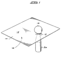
- FIG. 1 A method of locating a dent in the surface of a motor vehicle panel is described initially in broad terms with reference to Figure 1.
- a flat sheet of thin gauge steel representative of a panel is indicated with the reference numeral 10.
- Marked on one surface 14 of the sheet 10 is a point 12 and it is desired to locate a point on the opposite surface 16 of the sheet which is opposite to the point 12.
- the equipment used in the method of the invention comprises a metal or steel ball 18 which is free to roll about on the surface 14 and a permanent magnet 20 which is held against the surface 16.
- the ball 18 Being of magnetic material, the ball 18 is magnetised by the magnet 20 and is attracted to it through the steel sheet when the magnet is brought close to the ball.
- the magnet 20 can now be moved about, possibly manually, over the surface 16, drawing the ball 18 with it as it goes.
- An observer watching the surface 14 can give directions to another person who moves the magnet 20, in response to the directions, until such time as the ball 18 is brought to the point 12. When this point is reached by the ball, it is known that the magnet 20 is at the desired point on the surface 16.
- an electromagnet can be used instead of a permanent magnet.
- the magnet 20 forms part of a tool which is to be used on the surface 16 at the particular point which it is desired to locate.
- the magnet 20 and ball 18 can be used in a method of repairing dents in a motor vehicle panel, as described more fully below.
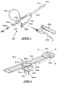
- a panel pressing device 22 is seen to comprise a plunger 24 which is slidably mounted in a housing 26.
- the plunger 24 can be urged out of housing 26 by means of a bell crank 28 pivotally mounted in the housing at a pivot 30.
- the bell crank acts against the bottom of the plunger to push it out of the housing.
- the bell crank is remotely operable by means of an actuating lever 32 which is attached pivotally to a handle 34.
- the lever 32 actuates the bell crank by means of a Bowden cable 36.
- the end of the plunger remote from the housing defines an operative end 38 which in use can be urged against a panel to treat any irregularities or dents in the panel.
- the operative end may assume a variety of shapes to suit the various applications to which it is put.
- a magnetized section is provided at this operative end of the plunger in the form of a permanent magnet 40.
- the magnet 40 can be attached to the plunger by adhesive tape and is used to attract a steel ball through the motor vehicle panel.
- the panel pressing device 22 also has means for locating the device securely on a reaction surface. With the device 22 located securely on a reaction surface, the plunger 24 can be urged by an operator out of the housing and against a panel.
- the locating means are in the form of a sharpened spigot 42 which protrudes from the bottom of the housing.
- the spigot is threaded at 44 so that an extension 46 can be fixed to the spigot.
- the threads of the spigot are also engagable with a complementally threaded bore provided in the housing.
- the length of the protruding spigot can thus be adjusted by screwing the spigot in and out of the housing.
- the spigot can be locked in any position by means of a wingnut 48.
- the holding means 50 comprises a base 52 which is carried by a pair of arms 54.
- the base has a reaction surface 56 on which the panel pressing device can be located.
- the base has a resilient upper layer which defines the reaction surface 56 and which increases the frictional engagement between the base and the sharpened spigot on the device.
- the device 22 can then be located securely on the base even when tilted over at an angle, such as when addressing a more remote or awkwardly situated irregularity in a panel.
- the arms 54 of the holding means are held securely in a circular clamp 58.
- the clamp has upper and lower locking discs 60 and 62 which clamp the arms between them. Loosening an adjustment nut 64 enables the disc 60 to be rotated slightly to unclamp the arms 54. These arms can then be moved in any radial or circumferential direction about the central circular clamp 58 to move the base to any desired position. Once at a chosen position, the disc 60 is tightened again to clamp the arms and is locked by means of the nut 64.
- the base 52 is now immobilised and provides a firm reaction surface for the panel pressing device.
- the holding means described above can be used in conjunction with a stand 66, or with a support which is passed through windows or doors on opposite sides of a vehicle cockpit.
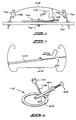
- a stand 66 is shown pictorially in Figure 4.
- the stand 66 has a central clamp 68 on which the holding means 50 can be mounted, and four radially extending arms 70.
- the clamp can be adjusted by means of an adjustment member 71 to allow scissors-type movement of the arms 70 about the central clamp 68.
- the adjustment member 71 can also be used to fix the holding means in various positions on the clamp 68.
- the clamp 68 is mounted on telescoping tubes 72 which can be locked relative to each other at any desired position so that the height of the stand can be adjusted.
- the telescoping tubes 72 also allow the arms 70 and platform 68 of the stand to be rotated relative to a support 74.
- the support 74 has four radially extending legs 76 with the free end of each leg 76 having a height adjustment screw 75 so that the stand can be located securely on an uneven surface.
- the stand 66 has retaining means in the form of clamps 78 provided at the end of each arm 70.
- the clamps 78 can be used to retain a panel in a fixed position relative to the stand while the base 52, which can be held adjustably by the holding means 50 in any other position, provides a reaction surface for the panel pressing device. While supported on the base, the plunger 24 of the device 22 can be pressed against the panel being held by the clamps 78.
- each radially extending arm of the stand comprises two telescoping members, with the outer telescoping member having an upstanding leg and a horizontal leg which can telescope in and out of the inner member. If necessary, this horizontal leg can be withdrawn completely from the inner member and then reinserted in a different orientation so that the upstanding leg is no longer upstanding, but assumes a substantially horizontal, or downwardly depending orientation. This may be required if the panel to be repaired is of an awkward shape.
- FIG. 5 A more detailed view of an upstanding leg of the stand is given in Figure 5.
- the top of the leg is provided with a rubber pad 80 on which the underside of a panel can rest.
- each arm of the stand will be adjusted so that the rubber pads support the panel near free edges of the panel.
- the panel can then be secured onto each pad by means of a clamping arm 82 in the form of a right-angled bar.
- the clamping arm 82 is mounted adjustably to the upstanding leg and can be locked in a variety of positions by means of wingnuts 84 and 86.
- the clamping arm 82 has a length of angle section 88 attached to its upper end which engages with a free edge of the panel and when suitably positioned, holds the panel securely onto the rubber pad.
- the stand can then be used to hold a motor vehicle panel, such as a door, bonnet or boot, for example, in a rigid position so that irregularities or dents in the panel can be treated by the panel pressing device 22.
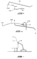
- the holding means 50 can also be mounted on a support passed through windows or doors on opposite sides of a vehicle cockpit. A pictorial view of this arrangement is shown in Figure 6. This method can be used to fix dents or hail damage in a vehicle roof 85.
- the lower disc 62 of the circular clamp 58 of the holding means 50 has depending threaded studs 89 and 90 having a plate 92 spanning across them.
- the studs 89 and 90 straddle a support in the form of a roof bar 94 with the plate 92 engaged underneath the bar.
- the plate 92 is bolted up tightly by nuts (not shown) on the studs to secure the holding means 50 securely on the roof bar 94.
- the holding means can be adjusted to position the base 52 and reaction surface where required.
- the roof bar is shown as being supported by gutter clamps 96 which engage with the gutter of the roof 85 and the upper door frames 98 of the vehicle, but could just as easily be supported by window sills on each side of the vehicle cockpit.
- the position of the base 52 can again be adjusted to provide a firm reaction surface for the panel pressing device 50 to repair a dent in the roof.
- the panel pressing device can of course be used on its own to repair dents in a vehicle bumper bar or fender for example. It is noted that neither this use, nor the panel pressing device per se, fall under the scope of the appended claims. Referring to Figure 7, where a top view of a vehicle fender 102 is shown schematically in outline, it will be seen that the reaction surface for the pressing device is provided by the fender bar itself.
- the device 22 is fitted with an adjustable extension 100 which abuts against an inner surface of one side of the fender so that the plunger 24 can be urged against a dent in the surface on the opposite side of the fender.
- the device could be supported off the floor, or any other convenient reaction surface.
- a further embodiment of the invention provides a lever or crowbar panel pressing tool 101 for treating irregularities in a panel.
- These tools shown schematically in Figure 9, can typically be used to fix dents in a vehicle roof, door or side body panel.
- the tools have operative ends 104 which can be urged about a fulcrum to act against a panel.
- Each tool has a permanent magnet 106 attached at or towards the operative end to attract a magnetic ball, such as a steel ball, on the other side of a vehicle panel.
- the fulcrum for each tool is provided by a bracket 108 which is mountable to a panel adjacent a free edge thereof.
- bracket is shown as a modified form of gutter clamp which is engagable with one of the gutters 110 provided at the edges of the vehicle roof. In such a position, an operator can then apply a force downwardly on the handle of the tool to supply an upwardly directed force against the vehicle roof 85.
- bracket such as the bracket 108 to provide a fulcrum for the panel pressing tools
- the panel pressing tool passes through the eye of the eyebolt, which then serves as a fulcrum for lever-type operation of the tool.
- a ball dispenser 112 is shown schematically in Figure 8.
- the dispenser 112 has a ball reservoir 114 from which balls can drop down a hollow tube 118 in single file to be held discretely in position in an ejection tube 120 by a magnet 122.
- the ejection tube is fitted with a spring-loaded plunger 124 which can be plunged into the ejection tube to eject the balls one by one, into the centre of a ring 123.
- the ring can be provided with a shroud (not shown) to retain an ejected ball and allow the dispenser to be used on an upright panel, such as a vehicle door panel for example, without losing an ejected ball.
- the underside of the ring is rubber lined to prevent scratching of the panel surface.
- the dispenser provides a convenient container for the steel balls used in the method provided by the invention.
- the apparatus described above can be used to fix dents in a vehicle panel as follows:
- a steel ball is dispensed from the ball dispenser onto the dented surface of a panel.
- a panel pressing device 22 or crowbar tool 101 is brought towards the location of the ball.
- the permanent magnet attached to the operative end of the device or tool will attract the ball through the vehicle panel.
- the panel pressing device or crowbar tool can be worked around the dent to draw the stretched or expanded metal generally back into the plane of the panel to restore a smooth surface to the panel.
- the apparatus can be used to good effect in conjunction with a heater.
- a heater is shown schematically in Figure 11.
- the heater is brought next to a dent in the panel to heat the surrounding paint. This renders the paint more flexible so that it will not crack while the dent is being repaired.
- modified tools can be provided that engage with the door opening surround of the vehicle, or with the window surround of the door.
Landscapes
- Engineering & Computer Science (AREA)
- Mechanical Engineering (AREA)
- Straightening Metal Sheet-Like Bodies (AREA)
- Vehicle Cleaning, Maintenance, Repair, Refitting, And Outriggers (AREA)
- Veneer Processing And Manufacture Of Plywood (AREA)
- Press Drives And Press Lines (AREA)
- Burglar Alarm Systems (AREA)
- Shaping Metal By Deep-Drawing, Or The Like (AREA)
Claims (10)
- Verfahren zum Loaklisieren und Reparieren einer Beule in einem Kraftfahrzeugblechteil (10, das eine Außenfläche, in der die Beule ausgebildet ist, und eine Innenfläche aufweist, wobei das Verfahren gekennzeichnet ist durch die Schritte des Lokalisierens einer magnetisierbaren Metallkugel (18) auf der Außenfläche des Blechs (10), des Lokalisierens eines Blechdrückwerkzeugs (22), das ein operatives Ende (38, 104) besitzt, das einen Magneten (40, 106) trägt, nahe der Innenfläche des Blechteils, so daß der Magnet die Kugel durch das Blechteil anzieht und bewirkt, daß sich die Kugel auf der Außenfläche bewegt, wenn das Blechdrückwerkzeug relative zu der Innenfläche bewegt wird, des Bewegens des Blechdrückwerkzeugs relative zu der Innenfläche derart, daß die Kugel sichtbar auf der Außenfläche des Blechteils zu der Stelle der Beule so bewegt wird, daß das Blechdrückwerkzeug dann anliegend an der Innenfläche an der Stelle der Beule positioniert ist, und des Reparierens der Beule durch das Betätigen des Blechdrückwerkzeugs, um eine nach außen gerichtete Druckkraft an der Innenfläche des Blechteils an der Position der Beule anzulegen, um dadurch die Beule auszubeulen.
- Verfahren nach Anspruch 1, dadurch gekennzeichnet, daß die Schritte des Lokalisierens und Reparierens der Beule in dem Blechteil (10) durchgeführt werden, ohne daß das Blechteil von dem Fahrzeug entfernt werden muß.
- Verfahren nach Anspruch 1 oder Anspruch 2, gekennzeichnet durch die weiteren Schritte des Vorsehens einer Stützeinrichtung (50), die eine Reaktionsfläche (52) definiert, und des Lokalisierens des Blechdrückwerkzeugs (22) derart, daß eine Reaktion gegen die Reaktionsfläche stattfindet, wenn das Werkzeug betätigt wird, um die nach außen gerichtete Druckkraft an der Innenfläche des Blechteils (10) an der Stelle der Beule anzulegen.
- Verfahren nach Anspruch 3, dadurch gekennzeichnet, daß das Blechdrückwerkzeug (22) ein Gehäuse (26), einen Kolben (24), der gleitend relative zu dem Gehäuse bewegbar ist, und einen Antriebsmechanismus (28, 30, 32, 34, 36) in der Form eines Kniehebels, der mit einem Bowdenzug betätigt wird, umfaßt, der betätigbar ist, um den Kolben in einer Richtung aus dem Gehäuse heraus zu drücken, wobei dar Kolben das operative Ende (38) vorsieht, das den Magneten (40) trägt, und daß das Verfahren den Schritt des Lokalisierens des Werkzeugs (22) relativ zu der Reaktionsfläche (52) in einer Art und Weise umfaßt, daß das Werkzeug gegen die Reaktionsfläche reagiert, wenn der Antriebsmechanismus betätigt wird, um den Kolben aus dem Gehäuse herauszudrücken, so daß das operative Ende gegen die Innenfläche des Blechteils (10) drückt.
- Verfahren nach Anspruch 1 oder Anspruch 2, dadurch gekennzeichnet, daß das Blechdrückwerkzeug (22) einen Hebel (101) umfaßt, dar das operative Ende (38) vorsleht, das den Magneten (40) trägt, und daß das Verfahren die Schritte des Befestigens eines Trägers (108) an dem Fahrzeug und des Betätigens des Hebels um einen Hebeldrehpunkt herum umfaßt, der von dem Träger vorgesehen wird, so daß das operative Ende des Hebels gegen die Innenfläche des Blechteils (10) drückt.
- Blechreparaturvorrichtung zum Reparieren einer Beule in einem Kraftfahrzeugblechteil (10), das eine Außenfläche, in der die Beule ausgebildet ist, und eine Innenfläche aufweist, wobei die Vorrichtung gekennzeichnet ist durch eine magnetisierbare Kugel (18), die an der Außenfläche des Blechteils (10) positioniert werden kann, und ein Blechdrückwerkzeug (22), das ein operatives Ende (38, 104) besitzt, das einen Magneten (40, 106) trägt und das nahe der Innenfläche des Blechs derart angeordnet werden kann, daß der Magnet die Kugel durch das Blech anzieht und bewirkt, daß sich die Kugel auf der Außenfläche zu der Position der Beule bewegt, wenn das Blechdrückwerkzeug relativ zu der Innenfläche zu der Position der Beule bewegt wird, wobei das Blechdrückwerkzeug dann betätigbar ist, um eine nach außen gerichtete Druckkraft an dem Blech an der Stelle der Beule anzulegen, um dadurch die Beule auszubeulen`
- Blechreparaturvorrichtung nach Anspruch 6, dadurch gekennzeichnet, daß das Blechdrückwerkzeug (22) ein Gehäuse (26), einen Kolben (24), der gleitend relativ zu dem Gehäuse bewegbar ist, und einen Antriebsmechanismus (28, 30, 32, 34, 36) in der Form eines Kniehebels, der durch einen Bowdenzug betätigt wird, umfaßt, wobei der Antriebsmechanismus betätigbar ist, um den Kolben in einer Richtung aus dem Gehäuse herauszudrücken, wobei der Kolben das operative Ende (38) bildet, das den Magneten (40) trägt.
- Blechreparaturvorrichtung nach Anspruch 7, dadurch gekennzeichnet, daß der Kniehebel (28) verschwenkbar relativ zu dem Gehäuse (26) angebracht ist und gegen den Kolben (24) wirkt und der Bowdenzug (36) an dem Kniehebel angebracht ist und fernbetätigt werden kann, um den Kniehebel derart zu verschwenken, daß der Kolben aus dem Gehäuse herausgedrückt wird.
- Blechreparaturvorrichtung nach Anspruch 7, gekennzeichnet durch eine freistehende Stützeinrichtung (50, 66), die eine Reaktionsfläche (52) definiert, wobei das Blechdrückwerkzeug (22) relativ zu der Stützeinrichtung (50, 66) derart positionierbar ist, daß das Werkzeug eine Reaktion gegen die Reaktionsfläche zeigt. wenn der Antriebsmechanismus (28, 30, 32, 34, 36) betätigt wird, um den Kolben (24) aus Gehäuse (26) herauszudrücken, so daß das operative Ende (38) des Kolbens an das Blechteil eine nach außen gerichtete Druckkraft anlegt.
- Blechreparaturvorrichtung nach Anspruch 6, dadurch gekennzeichnet, daß das Blechdrückwerkzeug (22) einen Hebel (101) umfaßt, der das operative Ende (104) vorsleht, das den Magneten (106) trägt, wobei die Vorrichtung einen Träger (108) umfaßt, der an einem Kraftfahrzeug befestigt werden kann und der einen Hebeldrehpunkt vorsieht, um den der Hebel derart betätigt werden kann, daß das operative Ende an die Innenfläche des Blechteils eine nach außen gerichtete Druckkraft anlegt.
Applications Claiming Priority (2)
| Application Number | Priority Date | Filing Date | Title |
|---|---|---|---|
| ZA928325 | 1992-10-28 | ||
| ZA928325 | 1992-10-28 |
Publications (2)
| Publication Number | Publication Date |
|---|---|
| EP0595593A1 EP0595593A1 (de) | 1994-05-04 |
| EP0595593B1 true EP0595593B1 (de) | 1999-04-14 |
Family
ID=25582268
Family Applications (1)
| Application Number | Title | Priority Date | Filing Date |
|---|---|---|---|
| EP93308509A Expired - Lifetime EP0595593B1 (de) | 1992-10-28 | 1993-10-26 | Lokalisierungsverfahren und Gerät zum Ausbeulen von Paneelen |
Country Status (7)
| Country | Link |
|---|---|
| US (1) | US5445000A (de) |
| EP (1) | EP0595593B1 (de) |
| AT (1) | ATE178818T1 (de) |
| AU (1) | AU668419B2 (de) |
| CA (1) | CA2109272C (de) |
| DE (1) | DE69324435T2 (de) |
| ZA (1) | ZA937598B (de) |
Families Citing this family (15)
| Publication number | Priority date | Publication date | Assignee | Title |
|---|---|---|---|---|
| JP2855421B2 (ja) * | 1996-01-15 | 1999-02-10 | 光政 石原 | 板金用引出し具 |
| US6026581A (en) * | 1996-03-27 | 2000-02-22 | Johnson Level & Tool Mfg. Co., Inc. | Pocket level with optional magnet |
| US20020112516A1 (en) * | 2001-10-22 | 2002-08-22 | James Akins | System For Removing Dents From Metal |
| US7498796B2 (en) * | 2002-05-09 | 2009-03-03 | The Boeing Company | Magnetic indexer for high accuracy hole drilling |
| US7124617B2 (en) * | 2003-01-14 | 2006-10-24 | Eric Richard Satterlee | Magnetic dent removal device, method and kit |
| US7444187B2 (en) * | 2003-02-14 | 2008-10-28 | Koninklijke Philips Electronics N.V. | Method for controlling lighting parameters, controlling device, lighting system |
| US20050052898A1 (en) * | 2003-09-05 | 2005-03-10 | Arntson Paul R. | Apparatus and methods for magnetic through-skin sensing |
| US20090049885A1 (en) * | 2006-11-20 | 2009-02-26 | Nerrit Scott Postma | Dent removal tool using rare earth magnets on probe tip to help locate tool tip |
| FR2930737B1 (fr) * | 2008-05-05 | 2010-09-03 | Sanchez Christian Sarrion | Appareillage pour le redresssement d'elements metalliques et/ou plastiques deformes a la suite d'une contrainte mecanique excessive |
| US8256084B1 (en) * | 2009-01-25 | 2012-09-04 | Your Dent Guy, Inc. | Metal stencil coin repair method |
| GB2479557B (en) * | 2010-04-14 | 2012-04-11 | Alan Wilkinson | Magnetic tip with trace for paintless dent removal rod |
| KR200478943Y1 (ko) * | 2013-12-24 | 2015-12-03 | 임영태 | 자동차용 판금공구 |
| CN108787797B (zh) * | 2018-08-31 | 2024-07-12 | 珠海市持久电子科技有限公司 | 汽车表面热处理修复系统及其修复方法 |
| CN114719727B (zh) * | 2022-03-25 | 2024-06-11 | 四川腾盾科技有限公司 | 基于磁石异极相吸的航空器成品装配定位检测方法 |
| CN116099900A (zh) * | 2022-12-01 | 2023-05-12 | 航天工程装备(苏州)有限公司 | 校平装置及校平方法 |
Citations (1)
| Publication number | Priority date | Publication date | Assignee | Title |
|---|---|---|---|---|
| US4754637A (en) * | 1987-04-14 | 1988-07-05 | Dell Danny W O | Electromagnetic dent removing tool |
Family Cites Families (42)
| Publication number | Priority date | Publication date | Assignee | Title |
|---|---|---|---|---|
| DE585733C (de) * | 1931-04-21 | 1933-10-14 | Stiles Herman Mfg Company | Werkzeug zum Ausrollen verbeulter Kotfluegel |
| US2165504A (en) * | 1936-04-04 | 1939-07-11 | Blackhawk Mfg Co | Portable hydraulic metal straightening machine |
| US2200133A (en) * | 1937-01-21 | 1940-05-07 | Blackhawk Mfg Co | Method of and means for straightening out deformed automobile bodies and the like |
| US2443931A (en) * | 1946-04-09 | 1948-06-22 | Charles M O Boyle | Car end straightener adjusting truck |
| US2543347A (en) * | 1948-10-25 | 1951-02-27 | Frank R Bartlo | Sheet metal working tool |
| US2696240A (en) * | 1949-10-28 | 1954-12-07 | Crowder John Hardin | Dent remover |
| US2599786A (en) * | 1950-11-03 | 1952-06-10 | Darrell D Schmeling | Shrinking hammer for sheet metal working |
| US3518864A (en) * | 1967-05-26 | 1970-07-07 | Joseph A Pietronuto | Automobile repair apparatus exerting a pulling force |
| CH559070A5 (de) * | 1973-01-08 | 1975-02-28 | Schill Erwin | |
| US3998081A (en) * | 1974-07-17 | 1976-12-21 | The Boeing Company | Electromagnetic dent puller |
| CH610232A5 (de) * | 1975-01-27 | 1979-04-12 | Erich K Schmitter | |
| US4073181A (en) * | 1975-06-23 | 1978-02-14 | Steinmann Jr Eugene B | Automobile body dent puller tool |
| AU507942B2 (en) * | 1975-12-22 | 1980-03-06 | Sunny Autos ny. Ltd | Vehicle body panels supporting frame |
| US4116031A (en) * | 1976-12-20 | 1978-09-26 | The Boeing Company | Flux concentrator for electromagnetic pulling |
| US4068750A (en) * | 1976-12-22 | 1978-01-17 | Borg-Warner Corporation | Automatic adjuster for clutch linkages |
| US4171631A (en) * | 1977-03-07 | 1979-10-23 | Butts Clifford L | Method of restoring deformed outer vehicle panel to its original contour |
| GB2035566B (en) * | 1977-06-23 | 1982-04-07 | Williamson D | Thickness measuring apparatus |
| US4116035A (en) * | 1977-09-08 | 1978-09-26 | Frank Malarsky | Dent puller |
| AU513761B2 (en) * | 1977-09-22 | 1980-12-18 | Boeing Co | Electromagnetic dent remover |
| US4144091A (en) * | 1977-12-01 | 1979-03-13 | Tran Nguon T | Window wipe |
| DE2834253C2 (de) * | 1978-08-04 | 1980-02-14 | Holsatia Magnet- + Zerspanungstechnik Gmbh, 2000 Hamburg | Magnetischer Ständer, insbesondere Meßstander |
| AU531188B2 (en) * | 1978-10-30 | 1983-08-11 | Hewson, A.J. | Clamp movable in several directions |
| US4252008A (en) * | 1979-02-16 | 1981-02-24 | Dibbens William L | Apparatus for removing dents from automobile bodies and the like |
| US4309894A (en) * | 1979-11-05 | 1982-01-12 | Connor Marc A | Auto body repair tool |
| SE417018B (sv) * | 1979-12-20 | 1981-02-16 | Bengt Wester | Anordning for att i byggnader lokalisera den exakta placeringen av dolda objekt |
| JPS56152542A (en) * | 1980-04-25 | 1981-11-26 | Honda Motor Co Ltd | Assembly and conveying device for vehicle body |
| US4479305A (en) * | 1982-03-12 | 1984-10-30 | Applied Power Inc. | Measuring bridge |
| AU595459B2 (en) * | 1983-12-20 | 1990-03-29 | James Herbert Mason | Vehicle gauging apparatus |
| GB8408472D0 (en) * | 1984-04-02 | 1984-05-10 | Broadaker Co Ltd | Clamping device |
| EP0163216A3 (de) * | 1984-05-30 | 1986-07-16 | Hans Gramlich | Richtvorrichtung für Automobilkarosserie |
| DE3516637A1 (de) * | 1985-05-09 | 1986-11-13 | Albert 3012 Langenhagen Herbst | Elektromagnet |
| WO1987003549A1 (en) * | 1985-12-11 | 1987-06-18 | Rodney Darcy Wall | Vehicle repair benches |
| US4753104A (en) * | 1986-11-03 | 1988-06-28 | Body Buddy, Inc. | Dent removing tool and method |
| AU605397B2 (en) * | 1988-01-05 | 1991-01-10 | Bevan Maxwell Flannery | Apparatus for repairing damaged vehicles |
| AU2875089A (en) * | 1988-01-22 | 1989-07-27 | Gerald Michale O'Brien | A support structure for cable joining jigs |
| US5170682A (en) * | 1988-08-19 | 1992-12-15 | Petersen Manufacturing Co., Inc. | Quick action bar clamp |
| AU2768489A (en) * | 1988-11-23 | 1990-05-31 | William George Stalder | Motor vehicle door support and aligning frame |
| US5094131A (en) * | 1990-02-14 | 1992-03-10 | Petersen Manufacturing Co., Inc. | Hand tool or improved bar clamp |
| US5005449A (en) * | 1990-02-14 | 1991-04-09 | Peterson Manufacturing Co., Inc. | Hand tool or improved bar clamp |
| US4977637A (en) * | 1990-02-16 | 1990-12-18 | Demers Rodney C | Magnetic window cleaning apparatus |
| FR2659262B3 (fr) * | 1990-03-08 | 1992-07-10 | Berna Philippe | Procede pour la realisation d'un outil de serrage a tampons, un tel outil et son procede d'utilisation. |
| US5078281A (en) * | 1990-10-30 | 1992-01-07 | Johnson Jeffrey E | Mechanic's work tray with magnetic swingable support bracket |
-
1993
- 1993-10-13 ZA ZA937598A patent/ZA937598B/xx unknown
- 1993-10-25 US US08/142,805 patent/US5445000A/en not_active Expired - Fee Related
- 1993-10-26 EP EP93308509A patent/EP0595593B1/de not_active Expired - Lifetime
- 1993-10-26 DE DE69324435T patent/DE69324435T2/de not_active Expired - Fee Related
- 1993-10-26 AU AU50247/93A patent/AU668419B2/en not_active Ceased
- 1993-10-26 AT AT93308509T patent/ATE178818T1/de not_active IP Right Cessation
- 1993-10-26 CA CA002109272A patent/CA2109272C/en not_active Expired - Fee Related
Patent Citations (1)
| Publication number | Priority date | Publication date | Assignee | Title |
|---|---|---|---|---|
| US4754637A (en) * | 1987-04-14 | 1988-07-05 | Dell Danny W O | Electromagnetic dent removing tool |
Also Published As
| Publication number | Publication date |
|---|---|
| US5445000A (en) | 1995-08-29 |
| CA2109272C (en) | 2000-11-07 |
| AU5024793A (en) | 1994-05-12 |
| ATE178818T1 (de) | 1999-04-15 |
| DE69324435T2 (de) | 1999-08-05 |
| CA2109272A1 (en) | 1994-04-29 |
| AU668419B2 (en) | 1996-05-02 |
| DE69324435D1 (de) | 1999-05-20 |
| EP0595593A1 (de) | 1994-05-04 |
| ZA937598B (en) | 1994-05-03 |
Similar Documents
| Publication | Publication Date | Title |
|---|---|---|
| EP0595593B1 (de) | Lokalisierungsverfahren und Gerät zum Ausbeulen von Paneelen | |
| US5707450A (en) | Apparatus for holding a vehicle body part | |
| US6533260B1 (en) | Adjustable, portable truck bed assembly holder | |
| US6490906B1 (en) | Vehicle body repair tool | |
| US5232035A (en) | Tire changing tool and workstand | |
| JPS62102964A (ja) | 多数の光フアイバ端面の同時研磨装置 | |
| US5479804A (en) | Tools for paintless dent repair | |
| US4252008A (en) | Apparatus for removing dents from automobile bodies and the like | |
| US8783638B2 (en) | Apparatus for supporting a wheel of a vehicle | |
| US5910198A (en) | Lug nut removal and tightening tool | |
| US5140784A (en) | Tool guide and contour sander for use therewith | |
| US6655185B2 (en) | Vehicle repairing device | |
| US20110146362A1 (en) | Device for straightening up deformed metal and/or plastic elements after undergoing an excessive mechanical stress | |
| US6105946A (en) | Apparatus for supporting and lifting a workpiece | |
| CN211387530U (zh) | 一种用于零件修复焊接的固定夹具 | |
| US3671032A (en) | Adjustable holding device | |
| US6116318A (en) | Mobile decal removal system | |
| US7104108B2 (en) | Dent repair system and method | |
| US4637114A (en) | Riveting apparatus | |
| US4324030A (en) | Apparatus for removing a grinding wheel | |
| US7302824B1 (en) | Portable press system for repairing automotive components | |
| CN114654892B (zh) | 一种具有定位功能的悬架弹簧自动喷码设备 | |
| US3164197A (en) | Tire tool | |
| US20080067311A1 (en) | Multi-position work stand | |
| US5426841A (en) | Method and tool for removing and replacing a vehicle wheel |
Legal Events
| Date | Code | Title | Description |
|---|---|---|---|
| PUAI | Public reference made under article 153(3) epc to a published international application that has entered the european phase |
Free format text: ORIGINAL CODE: 0009012 |
|
| AK | Designated contracting states |
Kind code of ref document: A1 Designated state(s): AT BE CH DE ES FR GB IT LI NL PT SE |
|
| 17P | Request for examination filed |
Effective date: 19941004 |
|
| 17Q | First examination report despatched |
Effective date: 19970523 |
|
| GRAG | Despatch of communication of intention to grant |
Free format text: ORIGINAL CODE: EPIDOS AGRA |
|
| GRAG | Despatch of communication of intention to grant |
Free format text: ORIGINAL CODE: EPIDOS AGRA |
|
| GRAH | Despatch of communication of intention to grant a patent |
Free format text: ORIGINAL CODE: EPIDOS IGRA |
|
| GRAH | Despatch of communication of intention to grant a patent |
Free format text: ORIGINAL CODE: EPIDOS IGRA |
|
| GRAA | (expected) grant |
Free format text: ORIGINAL CODE: 0009210 |
|
| AK | Designated contracting states |
Kind code of ref document: B1 Designated state(s): AT BE CH DE ES FR GB IT LI NL PT SE |
|
| PG25 | Lapsed in a contracting state [announced via postgrant information from national office to epo] |
Ref country code: SE Free format text: THE PATENT HAS BEEN ANNULLED BY A DECISION OF A NATIONAL AUTHORITY Effective date: 19990414 Ref country code: NL Free format text: LAPSE BECAUSE OF FAILURE TO SUBMIT A TRANSLATION OF THE DESCRIPTION OR TO PAY THE FEE WITHIN THE PRESCRIBED TIME-LIMIT Effective date: 19990414 Ref country code: LI Free format text: LAPSE BECAUSE OF FAILURE TO SUBMIT A TRANSLATION OF THE DESCRIPTION OR TO PAY THE FEE WITHIN THE PRESCRIBED TIME-LIMIT Effective date: 19990414 Ref country code: IT Free format text: LAPSE BECAUSE OF FAILURE TO SUBMIT A TRANSLATION OF THE DESCRIPTION OR TO PAY THE FEE WITHIN THE PRESCRIBED TIME-LIMIT;WARNING: LAPSES OF ITALIAN PATENTS WITH EFFECTIVE DATE BEFORE 2007 MAY HAVE OCCURRED AT ANY TIME BEFORE 2007. THE CORRECT EFFECTIVE DATE MAY BE DIFFERENT FROM THE ONE RECORDED. Effective date: 19990414 Ref country code: ES Free format text: THE PATENT HAS BEEN ANNULLED BY A DECISION OF A NATIONAL AUTHORITY Effective date: 19990414 Ref country code: CH Free format text: LAPSE BECAUSE OF FAILURE TO SUBMIT A TRANSLATION OF THE DESCRIPTION OR TO PAY THE FEE WITHIN THE PRESCRIBED TIME-LIMIT Effective date: 19990414 Ref country code: BE Free format text: LAPSE BECAUSE OF FAILURE TO SUBMIT A TRANSLATION OF THE DESCRIPTION OR TO PAY THE FEE WITHIN THE PRESCRIBED TIME-LIMIT Effective date: 19990414 Ref country code: AT Free format text: LAPSE BECAUSE OF FAILURE TO SUBMIT A TRANSLATION OF THE DESCRIPTION OR TO PAY THE FEE WITHIN THE PRESCRIBED TIME-LIMIT Effective date: 19990414 |
|
| REF | Corresponds to: |
Ref document number: 178818 Country of ref document: AT Date of ref document: 19990415 Kind code of ref document: T |
|
| REG | Reference to a national code |
Ref country code: CH Ref legal event code: EP |
|
| REF | Corresponds to: |
Ref document number: 69324435 Country of ref document: DE Date of ref document: 19990520 |
|
| PG25 | Lapsed in a contracting state [announced via postgrant information from national office to epo] |
Ref country code: PT Free format text: LAPSE BECAUSE OF FAILURE TO SUBMIT A TRANSLATION OF THE DESCRIPTION OR TO PAY THE FEE WITHIN THE PRESCRIBED TIME-LIMIT Effective date: 19990714 |
|
| ET | Fr: translation filed | ||
| NLV1 | Nl: lapsed or annulled due to failure to fulfill the requirements of art. 29p and 29m of the patents act | ||
| REG | Reference to a national code |
Ref country code: CH Ref legal event code: PL |
|
| PLBE | No opposition filed within time limit |
Free format text: ORIGINAL CODE: 0009261 |
|
| 26N | No opposition filed | ||
| PGFP | Annual fee paid to national office [announced via postgrant information from national office to epo] |
Ref country code: FR Payment date: 20011010 Year of fee payment: 9 |
|
| PGFP | Annual fee paid to national office [announced via postgrant information from national office to epo] |
Ref country code: GB Payment date: 20011024 Year of fee payment: 9 |
|
| PGFP | Annual fee paid to national office [announced via postgrant information from national office to epo] |
Ref country code: DE Payment date: 20011112 Year of fee payment: 9 |
|
| REG | Reference to a national code |
Ref country code: GB Ref legal event code: IF02 |
|
| PG25 | Lapsed in a contracting state [announced via postgrant information from national office to epo] |
Ref country code: GB Free format text: LAPSE BECAUSE OF NON-PAYMENT OF DUE FEES Effective date: 20021026 |
|
| PG25 | Lapsed in a contracting state [announced via postgrant information from national office to epo] |
Ref country code: DE Free format text: LAPSE BECAUSE OF NON-PAYMENT OF DUE FEES Effective date: 20030501 |
|
| GBPC | Gb: european patent ceased through non-payment of renewal fee | ||
| PG25 | Lapsed in a contracting state [announced via postgrant information from national office to epo] |
Ref country code: FR Free format text: LAPSE BECAUSE OF NON-PAYMENT OF DUE FEES Effective date: 20030630 |
|
| REG | Reference to a national code |
Ref country code: FR Ref legal event code: ST |