EP0595729A1 - Thermischer Verzögerer für Brandschutzklappe für Luftungskanäle - Google Patents
Thermischer Verzögerer für Brandschutzklappe für Luftungskanäle Download PDFInfo
- Publication number
- EP0595729A1 EP0595729A1 EP93420406A EP93420406A EP0595729A1 EP 0595729 A1 EP0595729 A1 EP 0595729A1 EP 93420406 A EP93420406 A EP 93420406A EP 93420406 A EP93420406 A EP 93420406A EP 0595729 A1 EP0595729 A1 EP 0595729A1
- Authority
- EP
- European Patent Office
- Prior art keywords
- gel
- liquid
- cooling
- reserve
- retarder according
- Prior art date
- Legal status (The legal status is an assumption and is not a legal conclusion. Google has not performed a legal analysis and makes no representation as to the accuracy of the status listed.)
- Withdrawn
Links
Images
Classifications
-
- A—HUMAN NECESSITIES
- A62—LIFE-SAVING; FIRE-FIGHTING
- A62C—FIRE-FIGHTING
- A62C2/00—Fire prevention or containment
- A62C2/06—Physical fire-barriers
- A62C2/08—Water curtains
-
- A—HUMAN NECESSITIES
- A62—LIFE-SAVING; FIRE-FIGHTING
- A62C—FIRE-FIGHTING
- A62C2/00—Fire prevention or containment
- A62C2/06—Physical fire-barriers
- A62C2/12—Hinged dampers
-
- F—MECHANICAL ENGINEERING; LIGHTING; HEATING; WEAPONS; BLASTING
- F24—HEATING; RANGES; VENTILATING
- F24F—AIR-CONDITIONING; AIR-HUMIDIFICATION; VENTILATION; USE OF AIR CURRENTS FOR SCREENING
- F24F13/00—Details common to, or for air-conditioning, air-humidification, ventilation or use of air currents for screening
- F24F13/24—Means for preventing or suppressing noise
-
- F—MECHANICAL ENGINEERING; LIGHTING; HEATING; WEAPONS; BLASTING
- F24—HEATING; RANGES; VENTILATING
- F24F—AIR-CONDITIONING; AIR-HUMIDIFICATION; VENTILATION; USE OF AIR CURRENTS FOR SCREENING
- F24F11/00—Control or safety arrangements
- F24F11/30—Control or safety arrangements for purposes related to the operation of the system, e.g. for safety or monitoring
- F24F11/32—Responding to malfunctions or emergencies
- F24F11/33—Responding to malfunctions or emergencies to fire, excessive heat or smoke
- F24F11/35—Responding to malfunctions or emergencies to fire, excessive heat or smoke by closing air passages
-
- F—MECHANICAL ENGINEERING; LIGHTING; HEATING; WEAPONS; BLASTING
- F24—HEATING; RANGES; VENTILATING
- F24F—AIR-CONDITIONING; AIR-HUMIDIFICATION; VENTILATION; USE OF AIR CURRENTS FOR SCREENING
- F24F2221/00—Details or features not otherwise provided for
- F24F2221/30—Details or features not otherwise provided for comprising fireproof material
Definitions
- the present invention relates to ventilation devices, integrated into ventilation networks for the ventilation of buildings and intended for the protection of premises against fire, these devices being typically fire dampers, smoke exhaust dampers or smoke dampers. transfer, placed inside ventilation ducts.
- the present invention seeks to remedy this situation, by providing ventilation devices of the type concerned with an improvement which limits and delays, in real fire conditions, the rise in temperature of these devices, thereby improving their fire stability, and thus allowing them to fully ensure, for a sufficient duration, their protective function such as that of fire barrier.
- the subject of the invention is a thermal retarder for a ventilation device integrated into an aeraulic network for the ventilation of a building and intended for the protection of premises against fire, such as a fire damper, smoke extraction flap or transfer flap, this thermal retarder being essentially constituted by a reserve of cooling product, in particular in the form of liquid or gel cooling, the release of which is triggered during the intervention of the device, the released cooling liquid or gel then spreading on the fixed part and / or on a movable shutter member of the ventilation device.
- the proposed device is simple and economical in design, and it adapts to all kinds of ventilation devices such as fire dampers, smoke exhaust dampers and the like, easily integrating into their metal structure, made of refractory material. or concrete.
- the reserve of liquid or cooling gel can be placed in a housing provided in the fixed part, such as a tunnel, of the ventilation device, or else be carried by a movable member of obturation, such as pivoting shutter blade, of this ventilation device.
- the intervention of a reserve of liquid or cooling gel integrated into the device also provides an autonomous and reliable embodiment, which is not dependent on an external liquid supply, unlike the usual fire and building protection systems.
- the reserve of cooling liquid or gel is formed in the form of at least one flexible bag filled with a volume of cooling liquid or gel.
- a particular embodiment provides for several elongated flexible pockets, filled with liquid or cooling gel, which are disposed respectively on the four faces of the tunnel of the ventilation device, in the region which surrounds the movable shutter member (s).
- several elongated flexible pockets, filled with liquid or cooling gel are arranged at the periphery and / or at the center of the movable obturation member, shaped as a pivoting rectangular blade.
- the flexible bag (s) advantageously have a wall made of hot-melt material, such as polyvinyl chloride, in contact with at least one element of the ventilation device which is liable to heat up, for example a metallic element.
- the liquid reserve is released automatically, the wall of the flexible bag piercing under the effect of heat, without the need for a particular mechanism.
- At least one element such as cord or braid, for example made of felt or ceramic fabric, is associated with the reserve of cooling liquid or gel, capable of being impregnated with the released cooling liquid or gel and ensuring distribution. of this liquid or gel.
- the released product thus remains correctly located, and it is distributed with a regular distribution, for example over the entire periphery of a obturation blade.
- the or each element such as cord or braid can be arranged either inside an elongated flexible bag filled with liquid or cooling gel, either outside the flexible bag, in contact with the wall of this flexible bag.
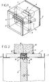
- FIG. 1 schematically represents a fire damper, comprising a tunnel 1 of rectangular section made of metal, of refractory material or concrete, provided with respective connection flanges 2 and 3 at its two ends.
- a pivoting rectangular shutter blade 5 also made of metal, refractory material or concrete.
- the shutter blade 5 is angularly movable between an open standby position and a closed fire stop position, under the action of a known trigger-reset control mechanism which has not been shown.
- the tunnel 1 of the fire damper contains a reserve of cooling liquid or gel, for example water (as described below) generally designated by the reference 6, extending in the region which surrounds the shutter blade 5 considered in the closed position.
- the cooling water reserve 6 here results from six elongated flexible pockets 7, each filled with a volume of water 8, which are distributed over the four sides of the tunnel 1 in correspondence with the four sides of the blade 5, the FIG. 2 being a sectional view passing through the flexible pocket 7 associated with the upper face of the tunnel 1.
- each flexible pocket 7 filled with water 8 is placed in a corresponding housing, delimited by a metallic intermediate frame 9 open in the direction of the blade 5, the frame 9 being however partially closed by intumescent seals 10, against which lips 11 are applied, carried by the periphery of the blade 5.
- This FIG. 2 also shows the connection of the tunnel 1 with a wall 12 by means of an external fixing frame 13.
- each flexible pocket 7 can be made of polyvinyl chloride (PVC), so that in the event of a fire, the wall of this pocket 7 melts in contact with the hot metal of the intermediate frame 9.
- PVC polyvinyl chloride
- each flexible pocket 7 contains a felt or ceramic fabric cord 14, impregnated with water 8, which temporarily retains this water when the pocket 7 is pierced and thus guarantees its good distribution over the periphery of the blade 5.
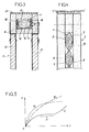
- FIG. 3 represents a variant, in which the cooling water reserve 6 is carried by the obturation blade 5, and not through the tunnel (not shown here).
- the blade 5, essentially and conventionally constituted by two parallel plates 15 of insulating material, has at its periphery a hollow part made of spongy refractory material 16, delimiting an internal channel 17 extending on the four sides of the blade 5.
- the channel 17 receives an elongated flexible pocket 7 filled with a volume of water 8.
- the channel 17 still contains two cords or braids in felt or ceramic fabric 18, which in this case are located outside the pocket 7, in contact with the wall thereof, as well as a polyvinyl chloride plate 19 on which the pocket 7 rests.
- FIG. 3 shows an intumescent seal 20 carried by the peripheral faces of the shutter blade 5.
- FIG. 4 illustrates another variant, in which the cooling water reserve 6 is disposed not at the periphery of the shutter blade 5, but in the central region of this blade 5, between its two parallel plates 15.
- the reserve 6 here comprises a plurality of flexible pockets 7, each filled with a volume of water 8.
- the opening of the pockets 7, releasing the water 8 kept in reserve can be obtained not only by melting in contact with a heated structural element, but also by the action of a thermostatic fuse, or by means of tips piercing the pockets 7 under the effect of expansion, or by any other means of thermal release. It is naturally advisable to avoid here any means which might cause a cold trip, for example during tests of the fire damper or the maintenance of this damper.
- Curve A corresponds to the maximum temperature imposed by the standards or prescriptions in force.
- Curve B represents the rise in temperature of a conventional fire damper, not provided with the thermal retarder according to the invention; it appears that in this case the temperature T comes fairly quickly to exceed the maximum prescribed value.
- Curve C represents the rise in temperature of a fire damper provided with the thermal retarder according to the invention; this curve C has a vaporization level P, thanks to which a noticeable slowing down in the rise in temperature is obtained, so that the curve C remains very long below the maximum admissible values, with a significant deviation from these values maximum.
- the water reserve of cooling consisting of several flexible pockets containing separate volumes of water, by a single flexible pocket.
- the flexible bag (s) can also be replaced by one or more tanks with a rigid or semi-rigid wall.
- the cooling water can be replaced by another coolant with a high thermal absorption capacity, or by a gel, or even by a pulverulent or solid product of equivalent properties.
Landscapes
- Engineering & Computer Science (AREA)
- Health & Medical Sciences (AREA)
- Public Health (AREA)
- Business, Economics & Management (AREA)
- Emergency Management (AREA)
- Chemical & Material Sciences (AREA)
- Combustion & Propulsion (AREA)
- Mechanical Engineering (AREA)
- General Engineering & Computer Science (AREA)
- Air-Flow Control Members (AREA)
Applications Claiming Priority (2)
| Application Number | Priority Date | Filing Date | Title |
|---|---|---|---|
| FR9213276A FR2697435B1 (fr) | 1992-10-29 | 1992-10-29 | Ralentisseur thermique pour appareil de ventilation destiné à la protection contre l'incendie. |
| FR9213276 | 1992-10-29 |
Publications (1)
| Publication Number | Publication Date |
|---|---|
| EP0595729A1 true EP0595729A1 (de) | 1994-05-04 |
Family
ID=9435225
Family Applications (1)
| Application Number | Title | Priority Date | Filing Date |
|---|---|---|---|
| EP93420406A Withdrawn EP0595729A1 (de) | 1992-10-29 | 1993-10-15 | Thermischer Verzögerer für Brandschutzklappe für Luftungskanäle |
Country Status (2)
| Country | Link |
|---|---|
| EP (1) | EP0595729A1 (de) |
| FR (1) | FR2697435B1 (de) |
Cited By (8)
| Publication number | Priority date | Publication date | Assignee | Title |
|---|---|---|---|---|
| FR2721830A1 (fr) * | 1994-07-01 | 1996-01-05 | Vraco Sa | Clapet coupe-feu |
| EP1302220A1 (de) * | 2001-10-09 | 2003-04-16 | Gebrüder Trox, Gesellschaft mit beschränkter Haftung | Klappe, insbesondere Brandschutzklappe |
| FR2843032A1 (fr) * | 2002-08-02 | 2004-02-06 | Aldes Aeraulique | Dispositif d'obturation d'un conduit de ventilation, notamment clapet coupe-feu ou volet de desenfumage |
| BE1018315A5 (nl) * | 2009-04-06 | 2010-08-03 | Rf Technologies Nv | Brandwerende ventilatieklep. |
| EP2537562A1 (de) * | 2011-06-23 | 2012-12-26 | Rf-Technologies nv | Rauchablassverschluss |
| WO2014032125A3 (en) * | 2012-08-27 | 2014-04-24 | Stuvex International Nv | Valve device and method for preventing explosion propagation |
| BE1020865A5 (nl) * | 2012-08-27 | 2014-06-03 | Stuvex Internat Nv | Klepinrichting en werkwijze voor het verhinderen van explosiepropagatie. |
| FR3028420A1 (fr) * | 2014-11-17 | 2016-05-20 | Mv Ind | Event de surpression pour systeme d'extinction automatique par gaz, dispositif coupe-feu equipe d'un tel event et procede de mise en œuvre de ce dispositif |
Citations (8)
| Publication number | Priority date | Publication date | Assignee | Title |
|---|---|---|---|---|
| GB191123403A (en) * | 1911-10-24 | 1912-10-24 | Percy Higson | Improvements in or relating to Fire Resisting Doors and Automatic Fire Extinguishing Apparatus. |
| US3172347A (en) * | 1962-11-13 | 1965-03-09 | American Warming Ventilation | Universal fire damper with angular axle |
| US3209837A (en) * | 1963-05-16 | 1965-10-05 | Morton A Freedman | Fire extinguishing apparatus |
| FR2212759A6 (de) * | 1972-08-03 | 1974-07-26 | Husson Jean | |
| GB2105987A (en) * | 1981-09-08 | 1983-04-07 | Leslie Thomas Homer | Smoke and fire protection screen |
| DE3234968A1 (de) * | 1982-09-17 | 1984-03-22 | Ernst Wirz AG Kipper- und Maschinenfabrik, 8707 Uetikon | Brandschutz-fluegeltueranordnung |
| FR2540730A1 (fr) * | 1983-02-16 | 1984-08-17 | Blanchon Louis | Rideau-ecran d'incendie, notamment pour des locaux de grandes dimensions |
| GB2198638A (en) * | 1986-12-19 | 1988-06-22 | George Alfred Forbes | Confining combustion products in a building structure |
-
1992
- 1992-10-29 FR FR9213276A patent/FR2697435B1/fr not_active Expired - Fee Related
-
1993
- 1993-10-15 EP EP93420406A patent/EP0595729A1/de not_active Withdrawn
Patent Citations (8)
| Publication number | Priority date | Publication date | Assignee | Title |
|---|---|---|---|---|
| GB191123403A (en) * | 1911-10-24 | 1912-10-24 | Percy Higson | Improvements in or relating to Fire Resisting Doors and Automatic Fire Extinguishing Apparatus. |
| US3172347A (en) * | 1962-11-13 | 1965-03-09 | American Warming Ventilation | Universal fire damper with angular axle |
| US3209837A (en) * | 1963-05-16 | 1965-10-05 | Morton A Freedman | Fire extinguishing apparatus |
| FR2212759A6 (de) * | 1972-08-03 | 1974-07-26 | Husson Jean | |
| GB2105987A (en) * | 1981-09-08 | 1983-04-07 | Leslie Thomas Homer | Smoke and fire protection screen |
| DE3234968A1 (de) * | 1982-09-17 | 1984-03-22 | Ernst Wirz AG Kipper- und Maschinenfabrik, 8707 Uetikon | Brandschutz-fluegeltueranordnung |
| FR2540730A1 (fr) * | 1983-02-16 | 1984-08-17 | Blanchon Louis | Rideau-ecran d'incendie, notamment pour des locaux de grandes dimensions |
| GB2198638A (en) * | 1986-12-19 | 1988-06-22 | George Alfred Forbes | Confining combustion products in a building structure |
Cited By (12)
| Publication number | Priority date | Publication date | Assignee | Title |
|---|---|---|---|---|
| FR2721830A1 (fr) * | 1994-07-01 | 1996-01-05 | Vraco Sa | Clapet coupe-feu |
| EP1302220A1 (de) * | 2001-10-09 | 2003-04-16 | Gebrüder Trox, Gesellschaft mit beschränkter Haftung | Klappe, insbesondere Brandschutzklappe |
| FR2843032A1 (fr) * | 2002-08-02 | 2004-02-06 | Aldes Aeraulique | Dispositif d'obturation d'un conduit de ventilation, notamment clapet coupe-feu ou volet de desenfumage |
| BE1018315A5 (nl) * | 2009-04-06 | 2010-08-03 | Rf Technologies Nv | Brandwerende ventilatieklep. |
| EP2239014A1 (de) | 2009-04-06 | 2010-10-13 | Rf-Technologies nv | Brandschutz-Absperrvorrichtung |
| EP2537562A1 (de) * | 2011-06-23 | 2012-12-26 | Rf-Technologies nv | Rauchablassverschluss |
| WO2014032125A3 (en) * | 2012-08-27 | 2014-04-24 | Stuvex International Nv | Valve device and method for preventing explosion propagation |
| BE1020865A5 (nl) * | 2012-08-27 | 2014-06-03 | Stuvex Internat Nv | Klepinrichting en werkwijze voor het verhinderen van explosiepropagatie. |
| US9452303B2 (en) | 2012-08-27 | 2016-09-27 | Sturvek International NV | Valve device and method for preventing explosion propagation |
| AU2013308339B2 (en) * | 2012-08-27 | 2017-04-13 | Stuvex International Nv | Valve device and method for preventing explosion propagation |
| FR3028420A1 (fr) * | 2014-11-17 | 2016-05-20 | Mv Ind | Event de surpression pour systeme d'extinction automatique par gaz, dispositif coupe-feu equipe d'un tel event et procede de mise en œuvre de ce dispositif |
| EP3025764A1 (de) * | 2014-11-17 | 2016-06-01 | MV Industrie | Druckentlastungsklappe für automatisches löschsystem durch gas, mit einer solchen druckentlastungsklappe ausgestattete brandschutzvorrichtung, und verfahren zum einsatz dieser vorrichtung |
Also Published As
| Publication number | Publication date |
|---|---|
| FR2697435A1 (fr) | 1994-05-06 |
| FR2697435B1 (fr) | 1994-12-16 |
Similar Documents
| Publication | Publication Date | Title |
|---|---|---|
| EP0595729A1 (de) | Thermischer Verzögerer für Brandschutzklappe für Luftungskanäle | |
| WO2020225313A1 (fr) | Coffre pour batterie | |
| FR2684306A1 (fr) | Dispositif d'aeration coupe-feu a elements statiques. | |
| CA2172445C (fr) | Garniture d'aeration coupe-feu et dispositif d'aeration equipe d'une telle garniture | |
| CN102017826A (zh) | 用于可操作的计算机数字数据存储装置的防火及防水罩 | |
| FR2680469A1 (fr) | Coupe-feu et procede pour bloquer un element de fermeture de coupe-feu. | |
| EP2958642A2 (de) | Sprinkler mit in position gehaltenem absperrteil mittels eines schmelzelements mithilfe einer beweglichen lagervorrichtung | |
| FR2701287A1 (fr) | Bâti dormant de porte, à structure modulaire. | |
| EP0058451A1 (de) | Automatisches Antiüberheizungssicherheitssystem für Fluidumröhren | |
| CA1185826A (en) | Ventilating device for cable ducts | |
| KR20210136548A (ko) | 방화 댐퍼 | |
| US4651772A (en) | Flow retarding valve for fire hydrants | |
| FR2511128A1 (fr) | Dispositif d'aeration a commande automatique | |
| FR3096116A1 (fr) | Systeme de ventilation d’un local | |
| JP3947318B2 (ja) | 火炎伝送防止装置 | |
| CN218957961U (zh) | 一种梯次电池包及电池消防装置 | |
| EP3427000A1 (de) | Isolierende wärmebarriere mit heissem und kaltem pcm | |
| ES2773648T3 (es) | Válvula de cierre para utilización en un conducto de un sistema de climatización o en un conjunto de ventilación de humo maquinal | |
| EP2732118B1 (de) | Brandschutzbauelement | |
| CN110124223B (zh) | 一种用于极寒条件下的家庭用自给防冻消防装置 | |
| JPH084449A (ja) | 遮熱スラット | |
| FR2499215A1 (fr) | Dispositif destine a eviter la deperdition de chaleur par un conduit de cheminee | |
| JPS6243107B2 (de) | ||
| FR2800620A1 (fr) | Dispositif coupe-feu formant element de conduit | |
| FR3047022A1 (fr) | Element d'enveloppe de batiment comprenant un materiau a changement de phase, et batiment correspondant |
Legal Events
| Date | Code | Title | Description |
|---|---|---|---|
| PUAI | Public reference made under article 153(3) epc to a published international application that has entered the european phase |
Free format text: ORIGINAL CODE: 0009012 |
|
| 17P | Request for examination filed |
Effective date: 19940224 |
|
| AK | Designated contracting states |
Kind code of ref document: A1 Designated state(s): AT BE CH DE DK ES FR GB GR IE IT LI LU MC NL PT SE |
|
| K1C1 | Correction of patent application (title page) published |
Effective date: 19940504 |
|
| 17Q | First examination report despatched |
Effective date: 19960412 |
|
| STAA | Information on the status of an ep patent application or granted ep patent |
Free format text: STATUS: THE APPLICATION HAS BEEN WITHDRAWN |
|
| 18W | Application withdrawn |
Withdrawal date: 19960627 |