EP0595901B1 - Karde mit schutzeinrichtung - Google Patents
Karde mit schutzeinrichtung Download PDFInfo
- Publication number
- EP0595901B1 EP0595901B1 EP92915691A EP92915691A EP0595901B1 EP 0595901 B1 EP0595901 B1 EP 0595901B1 EP 92915691 A EP92915691 A EP 92915691A EP 92915691 A EP92915691 A EP 92915691A EP 0595901 B1 EP0595901 B1 EP 0595901B1
- Authority
- EP
- European Patent Office
- Prior art keywords
- carding engine
- door
- engine
- carding
- arrangement
- Prior art date
- Legal status (The legal status is an assumption and is not a legal conclusion. Google has not performed a legal analysis and makes no representation as to the accuracy of the status listed.)
- Expired - Lifetime
Links
Images



Classifications
-
- F—MECHANICAL ENGINEERING; LIGHTING; HEATING; WEAPONS; BLASTING
- F16—ENGINEERING ELEMENTS AND UNITS; GENERAL MEASURES FOR PRODUCING AND MAINTAINING EFFECTIVE FUNCTIONING OF MACHINES OR INSTALLATIONS; THERMAL INSULATION IN GENERAL
- F16P—SAFETY DEVICES IN GENERAL; SAFETY DEVICES FOR PRESSES
- F16P1/00—Safety devices independent of the control and operation of any machine
- F16P1/02—Fixed screens or hoods
-
- D—TEXTILES; PAPER
- D01—NATURAL OR MAN-MADE THREADS OR FIBRES; SPINNING
- D01G—PRELIMINARY TREATMENT OF FIBRES, e.g. FOR SPINNING
- D01G31/00—Warning or safety devices, e.g. automatic fault detectors, stop motions
Definitions
- This invention relates to a carding engine guard which is intended to shield operating personnel from coming into contact with the rotating parts of a carding engine.
- the doors project out into any transit path alongside the card, when they are in the open position, and which may therefore impede traffic of personnel or equipment alongside the machine. Also, by this arrangement of the doors, when the doors are open they do not allow easy access to all parts of the card, both by obstruction by the doors themselves, and also by parts of the support frame on which the doors are hingedly mounted.
- a carding engine guard arrangement comprising a carding engine having respective guards arranged along each side of the carding engine and extending generally parallel to the longitudinal axis of the carding engine, each guards being movable between a closed position in which the guard shields the associated side parts of the carding engine and an open position in which the guard allows access to be had to the side parts of the carding engine for servicing / repair purposes, in which at least one of the guards comprises:
- a carding engine guard arrangement comprising a carding engine having respective guards arranged along each side of the carding engine and extending generally parallel to the longitudinal axis of the carding engine, each guards being movable between a closed position in which the guard shields the associated side parts of the carding engine and an open position in which the guard allows access to be had to the side parts of the carding engine for servicing / repair purposes, in which at least one of the guards comprises:
- the respective side of the carding engine can be reliably guarded when the door arrangement is in the closed position, but when the door arrangement is upwardly pivoted to the raised position, it can allow full i.e. unimpeded access to the entire length of the carding engine which is covered by the door arrangement when in the closed position.
- the door arrangement extends substantially throughout the length of the carding engine, so that a unitary structure is provided which is movable in order to guard, or uncover one entire side of the engine.
- the door arrangement can be made in any suitable form to perform a guarding function, and in one preferred form may be formed at least partly of a grid or mesh structure to enable the working of the engine to be viewed through the guard structure.
- a particularly advantageous form of the door arrangement comprises a pair of upper and lower folding door panels, the lower panel being hinged to the upper panel along an upper edge of the lower panel, and the upper panel being hinged along its upper edge to form the horizontal top hinge axis of the door arrangement.
- This is preferable to a single door panel which may project laterally of the carding engine to an unacceptable extent when in the open position, if it is made of substantial height to shield all of the side of the carding engine (when in the closed position).
- the lower door panel is first hinged upwardly through approximately 180° to form a folded door assembly and which allows access to the lower side parts only of the carding engine.
- the folded door assembly is hinged upwardly about the top hinge axis through approximately 90°.
- the bottom edge of the door assembly can be locked to the floor, and when the assembly is moved to its raised position, no obstruction is presented to full access to the entire side and ends of the carding engine, and without blocking passage to traffic to move alongside the engine i.e. there is no need for a rectangular fixed frame alongside the carding engine in which conventional guards are mounted, and which can impede access to the carding engine.
- a safety interlock is provided, linked to the operation of the engine, and which is triggered to allow upward pivoting of the folded door assembly to the raised position only after the lower panel has first completed its upward hinging movement and when the engine is inoperative.
- a respective door arrangement as defined above, with or without the preferred aspects thereof, is provided along each side of the carding engine.
- a magnet and proximity switch is provided on the lower door panel, which initiates release of the door arrangement to carry out its further movement to the raised position when the lower door panel has completed its movement.
- the magnet may retain the lower door panel against the upper door panel by co-operation with a suitable magnetic part of the upper panel, when the lower door panel is upwardly hinged to lie alongside the upper door panel.
- the opposite ends of the engine may be guarded by separate guard panels which can be of any suitable one of existing designs, and preferably also of such a kind as to be readily removable when required.
- the support structure may be formed on, or by part of the support frame or superstructure of the carding engine, and more preferably, the usual cylinder "bend" structure of the carding engine.
- a carding engine guard arrangement according to the invention will now be described in detail, and comprising a carding engine 10 having a general longitudinal axis, and respective guards 11 arranged along each side of the engine.
- guards will be provided to shield each end of the engine 10.
- Figure 2 shows a fully closed position of a guard door arrangement 12 on the left hand side of the carding engine, and a fully raised position of the right hand guard door arrangement.
- Figure 1 shows schematically initial stages in the movement of the right hand door arrangement from the closed position to the raised position.
- Door arrangement 12 comprises upper and lower folding door panels 14 and 15, with the lower panel 15 being hinged to the upper panel 14 along an upper edge 16 of the lower panel 15 and the upper panel 14 being hinged along its upper edge 17 (see Figure 1) to form the horizontal top hinge axis of the folding door panel assembly.
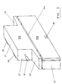
- FIG. 3 A further embodiment is illustrated schematically in Figure 3, and generally corresponding parts are designated by the same reference numerals, but with the addition of the letter a.
- the panels 14a, 15a form part of a closure housing assembly which can move as a unit about upper hinges 20 to a fully open position after initial upward hinging movement of the lower panel 15a about hinge axis 16a to overlie the upper panel 14a.
- the unit assembly including panels 14a, 15a, top panel 21, end panels 22 and projecting side panels 23 can then move bodily to a stable open position by upward pivoting of the assembly about hinges 20.
- Lower end panels 24 will, however, remain fixed, and form part of a permanent end guard panel assembly of the carding engine.
- a magnetic and proximity switch 18 is provided on the lower door panel 15a, which initiates release of the door arrangement to carry out its further movements to the raised position when the lower door panel has completed its upward hinging movement.
- the magnet retains the lower door panel 15a alongside the upper door panel 14a by co-operation with a suitable magnetic part on the upper panel, and safety interlock 19 can then be operated to release the folded door assembly for further joint upward hinging movement about top hinges 20.
- FIG. 4 to 6 this shows a practical version of the schematic illustration of Figure 3, and with Figure 4 showing the closed guarding position, Figure 5 showing an intermediate partly open position, and Figure 6 showing the fully open position. Parts corresponding with the parts shown in Figure 3 are given the same references and will not be described in detail again.
- the folding door guard arrangement of Figures 4 to 6 forms part of the external housing structure in which a carding engine is arranged, and also associated parts e.g. "bend" structure, travelling flats etc.
- the guard arrangement is illustrated as being hingedly mounted on an upper part 25 of a support structure of a housing 26 within which the carding engine and related parts are mounted.
Landscapes
- Engineering & Computer Science (AREA)
- General Engineering & Computer Science (AREA)
- Textile Engineering (AREA)
- Mechanical Engineering (AREA)
- Superstructure Of Vehicle (AREA)
- Preliminary Treatment Of Fibers (AREA)
Claims (10)
- Karden-Schutzanordnung, mit einer Karde (10), die Schutzeinrichtungen (11) aufweist, die entlang jeder Seite der Karde angeordnet sind und sich allgemein parallel zu der Längsachse der Karde erstrecken, wobei jede Schutzeinrichtung zwischen einer geschlossenen Stellung, in welcher die Schutzeinrichtung die zugeordneten Seitenteile der Karde abgeschirmt, und einer offenen Stellung beweglich ist, in welcher die Schutzeinrichtung einen Zugang zu den Seitenteilen der Karde für Wartungs/Reparaturzwecke erlaubt, wobei wenigstens eine der Schutzeinrichtungen aufweist:eine Tragstruktur (25), die entlang einer Seite der Karde über den Seitenteilen der Karde angeordnet ist, die während des Betriebs abgeschirmt werden müssen, zu denen jedoch für Wartungs-/Reparaturvorgänge Zugang erforderlich ist, undeine Türanordnung (12), die auf der Tragstruktur (25) schwenkbar so angebracht ist, daß sie um eine im wesentlichen horizontale Schwenkachse (13, 17, 20) an der oder in der Nähe der oberen Kante der Türanordnung zwischen der geschlossenen und offenen Stellung verschwenken kann, wobei die Türanordnung ein Paar aus einer oberen und einer unteren Falttürplatte (14, 15) aufweist, von denen die untere Platte (15) an der oberen Platte (14) entlang einer oberen Kante (16) der unteren Platte (15) angelenkt ist und die obere Platte (14) entlang ihrer oberen Kante angelenkt ist und so die horizontale obere Schwenkachse (13, 17, 20) der Türanordnung bildet.
- Karden-Schutzanordnung mit einer Karde (10), die Schutzeinrichtungen (11) aufweist, die entlang jeder Seite der Karde angeordnet sind und sich allgemein parallel zu der Längsachse der Karde erstrecken, wobei jede Schutzeinrichtung zwischen einer geschlossenen Stellung, in welcher die Schutzeinrichtung die zugeordneten Seitenteile der Karde abschirmt, und einer offenen Stellung beweglich ist, in welcher die Schutzeinrichtung einen Zugang zu den Seitenteilen der Karde für Wartungs-/Reparaturzwecke erlaubt, wobei wenigstens eine der Schutzeinrichtungen aufweist:eine Tragstruktur (25), die entlang einer Seite der Karde über den Seitenteilen der Karde angeordnet ist, die während des Betriebs abgeschirmt werden müssen, zu denen jedoch für Wartungs-/Reparaturvorgänge Zugang erforderlich ist, wobei die Tragstruktur (25) einen Teil der Seitenrahmenstruktur der Karde bildet, undeine Türanordnung (12), die auf der Tragstruktur (25) schwenkbar so angebracht ist, daß sie um eine im wesentlichen horizontale Schwenkachse (13, 17, 20) an der oder in der Nähe der Oberkante der Türanordnung zwischen der geschlossenen Stellung, die die zugeordnete Seite der Karde abschirmt, und einer angehobenen offenen Stellung verschwenken kann, die einen Zugang zu den Seitenteilen der Karde erlaubt, wenn letztere sich nicht in Betrieb befindet, wobei die Türanordnung (12) einen ungehinderten Zugang über die gesamte Länge der Seitenteile der Karde bereitstellt, wenn die Türanordnung sich in der angehobenen offenen Stellung befindet.
- Karden-Schatzanordnung nach Anspruch 1 oder 2, bei der die Türanordnung eine Gitter- oder Maschenstruktur aufweist, damit das Arbeiten der Karde durch die Schutzstruktur beobachtet werden kann.
- Karden-Schutzanordnung nach Anspruch 2, bei der die Türanordnung (12) ein Paar aus einer oberen und einer unteren Falttürplatte (14, 15) aufweist, von denen die untere Platte (15) an die obere Platte (14) entlang einer oberen Kante (16) der unteren Platte (15) angelenkt ist und von denen die obere Platte (14) entlang ihrer oberen Kante angelenkt ist, so daß sie die horizontale obere Schwenkachse (13, 17, 20) der Türanordnung zu bildet.
- Karden-Schutsanordnang nach Anspruch 1 oder 4, bei der die untere Türplatte (15) um ungefähr 180° aufwärts schwenkbar beweglich ist, sodaß eine gefaltete Türanordnung gebildet wird und Zugang zu den unteren Seitenteilen der Karde ermöglicht wird, woraufhin die gefaltete Türanordnung aufwärts um die obere Schwenkachse (13, 17, 20) um ungefähr 90 schwenkbar ist und so die angehobene Zugangsstellung einnimmt, wenn über die gesamte Höhe der Seitenteile der Karde ein vollständiger Zugang erforderlich ist.
- Karden-Schutzanordnung nach einem der Ansprüche 1 bis 5, bei der die Bodenkante der Türanordnung am Boden verriegelbar ist, wobei dann, wenn der Aufbau (12) in seine angehobene offene Stellung bewegt ist, der vollständige Zugang zu der gesamten Seite und den Enden der Karde (10) ungehindert möglich ist.
- Karden-Schutzanordnung nach Anspruch 5, bei der ein Sicherheitsriegel (19) vorgesehen ist, der mit dem Betrieb der Karde (10) verbunden und so angeordnet und eingerichtet ist, daß er ausgelöst wird und ein Aufwärtsschwenken des gefalteten Türaufbaus (12) in die angehobene Stellung nur zuläßt, nachdem die untere Platte (15) zuerst ihre Aufwärtsschwenkbewegung beendet hat und wenn die Karde (10) sich nicht in Betrieb befindet.
- Karden-Schutzanordnung nach einem der Ansprüche 1 bis 7, die entlang jeder Seite der Karde (10) vorgesehen ist.
- Karden-Schutzanordnung nach Anspruch 4 oder 5, bei der ein Magnet und ein Näherungsschalter (18a) auf der unteren Türplatte (15a) vorgesehen und so betätigbar sind, daß die Freigabe der Türanordnung (12) eingeleitet und ihre weitere Bewegung in die angehobene Stellung ausgeführt wird, wenn die untere Türplatte (15) ihre Bewegung beendet hat.
- Karden-Schutzanordnung nach Anspruch 1 oder 2, bei der die Tragstruktur (10) einen Teil der "gebogenen" Struktur der Karde (10) umfaßt.
Applications Claiming Priority (3)
| Application Number | Priority Date | Filing Date | Title |
|---|---|---|---|
| GB919115881A GB9115881D0 (en) | 1991-07-23 | 1991-07-23 | Card engine guard |
| GB9115881 | 1991-07-23 | ||
| PCT/GB1992/001340 WO1993002237A1 (en) | 1991-07-23 | 1992-07-21 | Carding engine guard |
Publications (2)
| Publication Number | Publication Date |
|---|---|
| EP0595901A1 EP0595901A1 (de) | 1994-05-11 |
| EP0595901B1 true EP0595901B1 (de) | 1997-07-02 |
Family
ID=10698823
Family Applications (1)
| Application Number | Title | Priority Date | Filing Date |
|---|---|---|---|
| EP92915691A Expired - Lifetime EP0595901B1 (de) | 1991-07-23 | 1992-07-21 | Karde mit schutzeinrichtung |
Country Status (7)
| Country | Link |
|---|---|
| US (1) | US5537717A (de) |
| EP (1) | EP0595901B1 (de) |
| JP (1) | JPH06509396A (de) |
| CN (1) | CN1073990A (de) |
| DE (1) | DE69220669T2 (de) |
| GB (1) | GB9115881D0 (de) |
| WO (1) | WO1993002237A1 (de) |
Families Citing this family (9)
| Publication number | Priority date | Publication date | Assignee | Title |
|---|---|---|---|---|
| US5845081A (en) * | 1996-09-03 | 1998-12-01 | Sun Microsystems, Inc. | Using objects to discover network information about a remote network having a different network protocol |
| KR100464719B1 (ko) * | 2002-05-13 | 2005-01-06 | 주식회사 웅천텍스텍 | 바잘트섬유의 제조방법 및 장치 |
| DE10242929A1 (de) * | 2002-09-16 | 2004-03-18 | Trützschler GmbH & Co KG | Vorrichtung an einer Spinnereivorbereitungsmaschine, insbesondere Karde, mit einer Maschinenverkleidung |
| DE10259475A1 (de) * | 2002-12-19 | 2004-07-01 | Trützschler GmbH & Co KG | Vorrichtung an einer Spinnereivorbereitungsmaschine, insbes. Karde, Reiniger o. dgl., mit einer Maschinenverkleidung |
| FR2881147B1 (fr) * | 2005-01-26 | 2007-04-13 | Thibeau Soc Par Actions Simpli | Carde comportant des moyens de recouvrement mobiles en translation |
| EP2037016A1 (de) * | 2007-09-11 | 2009-03-18 | Oskar Dilo Maschinenfabrik KG | Krempel mit Gehäuse |
| CN104532412A (zh) * | 2014-11-25 | 2015-04-22 | 青岛源泉机械有限公司 | 一种梳理机全封闭罩壳 |
| JP6526596B2 (ja) * | 2016-04-15 | 2019-06-05 | 高松機械工業株式会社 | 工作機械 |
| CN115874900B (zh) * | 2021-09-29 | 2025-10-28 | 泰科电子(上海)有限公司 | 防护罩和机器设备 |
Family Cites Families (9)
| Publication number | Priority date | Publication date | Assignee | Title |
|---|---|---|---|---|
| US1335082A (en) * | 1918-10-04 | 1920-03-30 | George B Stowe | Automobile-engine hood and drain-trough therefor |
| US1736718A (en) * | 1924-01-28 | 1929-11-19 | Packard Motor Car Co | Motor vehicle |
| CH399966A (it) * | 1962-09-06 | 1965-09-30 | Bettoni Ezio | Apparecchio per cardare e stirare fibre tessili |
| FR1476615A (fr) * | 1965-11-30 | 1967-04-14 | Neu Sa | Perfectionnements aux installations de dépoussiérage et d'évacuation des déchetspour machines textiles |
| US4364151A (en) * | 1980-07-22 | 1982-12-21 | Trutzschler Gmbh & Co. Kg | Accident prevention system for machines having one or more movable components |
| US4484845A (en) * | 1982-12-13 | 1984-11-27 | Textron, Inc. | Machine tool safety shield |
| FR2539767A1 (fr) * | 1983-01-21 | 1984-07-27 | Mat Textil Ste Alsa Const | Casque central de protection pour machine a tisser et machine a tisser equipee d'un tel casque central |
| IT1201297B (it) * | 1985-05-21 | 1989-01-27 | Marcello Giuliani | Protezione antinfortunistica per impianti di cardatura delle industrie tessili e per altri impieghi |
| EP0340458B1 (de) * | 1988-04-29 | 1993-08-11 | Maschinenfabrik Rieter Ag | Vorrichtung zum Entstauben einer Karde |
-
1991
- 1991-07-23 GB GB919115881A patent/GB9115881D0/en active Pending
-
1992
- 1992-07-21 DE DE69220669T patent/DE69220669T2/de not_active Expired - Fee Related
- 1992-07-21 JP JP5502697A patent/JPH06509396A/ja active Pending
- 1992-07-21 WO PCT/GB1992/001340 patent/WO1993002237A1/en not_active Ceased
- 1992-07-21 US US08/182,107 patent/US5537717A/en not_active Expired - Fee Related
- 1992-07-21 EP EP92915691A patent/EP0595901B1/de not_active Expired - Lifetime
- 1992-07-23 CN CN92109747A patent/CN1073990A/zh active Pending
Also Published As
| Publication number | Publication date |
|---|---|
| CN1073990A (zh) | 1993-07-07 |
| DE69220669T2 (de) | 1998-01-02 |
| DE69220669D1 (de) | 1997-08-07 |
| WO1993002237A1 (en) | 1993-02-04 |
| US5537717A (en) | 1996-07-23 |
| EP0595901A1 (de) | 1994-05-11 |
| GB9115881D0 (en) | 1991-09-04 |
| JPH06509396A (ja) | 1994-10-20 |
Similar Documents
| Publication | Publication Date | Title |
|---|---|---|
| US5299386A (en) | Safety gate assembly | |
| US5537717A (en) | Carding engine guard | |
| EP1400387B1 (de) | Abdeckungskonstruktion für kühlpaket einer baumaschine | |
| US4392669A (en) | Cab for lift truck with swing out windshield | |
| US4886411A (en) | Protective means for a lifting/tilting or tilting device | |
| CN1275467A (zh) | 具有加工区外罩的机床 | |
| US12179300B2 (en) | Protective shroud and machine | |
| US4765155A (en) | Circular knitting machine with cloth take up safety gate | |
| US5183093A (en) | Removable sealing device for a raisable-curtain industrial door | |
| CA1181029A (en) | Isolating device for an opening traversed by conveyor cars | |
| CA2321484C (en) | A cab for earth-moving machines | |
| US4890450A (en) | Spinning machine with a device to service spinning and winding stations | |
| SK279752B6 (sk) | Bezpečnostná závora | |
| CA2089399C (en) | Roller door | |
| JPH07205250A (ja) | 射出成形機における安全扉装置 | |
| KR102519329B1 (ko) | 지게차의 기계실 개폐 도어 | |
| WO2001017843A1 (en) | Screen assembly for fork-lift trucks | |
| CN223423862U (zh) | 用于施工机械的折叠门装置及施工机械 | |
| CN214771363U (zh) | 一种机箱自动打磨机的防护装置 | |
| JP3838419B2 (ja) | カウンタバランス型バッテリフォークリフト | |
| JP2526932Y2 (ja) | 建設機械 | |
| CN210168354U (zh) | 一种用于电器设备的视窗防护罩 | |
| ITBS960048A1 (it) | Struttura protettiva per macchine utensili a ponte fisso e tavola o tavole mobili | |
| JP2580612Y2 (ja) | 工作機械のカバー | |
| JP2596344Y2 (ja) | 折畳み扉装置 |
Legal Events
| Date | Code | Title | Description |
|---|---|---|---|
| PUAI | Public reference made under article 153(3) epc to a published international application that has entered the european phase |
Free format text: ORIGINAL CODE: 0009012 |
|
| 17P | Request for examination filed |
Effective date: 19940130 |
|
| AK | Designated contracting states |
Kind code of ref document: A1 Designated state(s): CH DE LI |
|
| 17Q | First examination report despatched |
Effective date: 19941229 |
|
| GRAG | Despatch of communication of intention to grant |
Free format text: ORIGINAL CODE: EPIDOS AGRA |
|
| GRAH | Despatch of communication of intention to grant a patent |
Free format text: ORIGINAL CODE: EPIDOS IGRA |
|
| GRAH | Despatch of communication of intention to grant a patent |
Free format text: ORIGINAL CODE: EPIDOS IGRA |
|
| GRAA | (expected) grant |
Free format text: ORIGINAL CODE: 0009210 |
|
| AK | Designated contracting states |
Kind code of ref document: B1 Designated state(s): CH DE LI |
|
| REG | Reference to a national code |
Ref country code: CH Ref legal event code: EP |
|
| REF | Corresponds to: |
Ref document number: 69220669 Country of ref document: DE Date of ref document: 19970807 |
|
| REG | Reference to a national code |
Ref country code: CH Ref legal event code: NV Representative=s name: KELLER & PARTNER PATENTANWAELTE AG |
|
| PLBE | No opposition filed within time limit |
Free format text: ORIGINAL CODE: 0009261 |
|
| STAA | Information on the status of an ep patent application or granted ep patent |
Free format text: STATUS: NO OPPOSITION FILED WITHIN TIME LIMIT |
|
| 26N | No opposition filed | ||
| PGFP | Annual fee paid to national office [announced via postgrant information from national office to epo] |
Ref country code: DE Payment date: 19980629 Year of fee payment: 7 |
|
| PGFP | Annual fee paid to national office [announced via postgrant information from national office to epo] |
Ref country code: CH Payment date: 19980701 Year of fee payment: 7 |
|
| PG25 | Lapsed in a contracting state [announced via postgrant information from national office to epo] |
Ref country code: LI Free format text: LAPSE BECAUSE OF NON-PAYMENT OF DUE FEES Effective date: 19990731 Ref country code: CH Free format text: LAPSE BECAUSE OF NON-PAYMENT OF DUE FEES Effective date: 19990731 |
|
| REG | Reference to a national code |
Ref country code: CH Ref legal event code: PL |
|
| PG25 | Lapsed in a contracting state [announced via postgrant information from national office to epo] |
Ref country code: DE Free format text: LAPSE BECAUSE OF NON-PAYMENT OF DUE FEES Effective date: 20000503 |